Table of Contents
Advertisement
Quick Links
with wireless remote control
KNF Neuberger GmbH
Alter Weg 3
D-79112 Freiburg
Germany
Phone ++49 / (0)7664 / 5909-0
Fax ++49 / (0)7664 / 5909-99
E-Mail:
info@knf.de
www.knf.de
KNF 121308-121311 07/18
Translation of original Operating Instructions, english
Operating Instructions
Read and observe this Operating Instructions!
Vacuum pump system
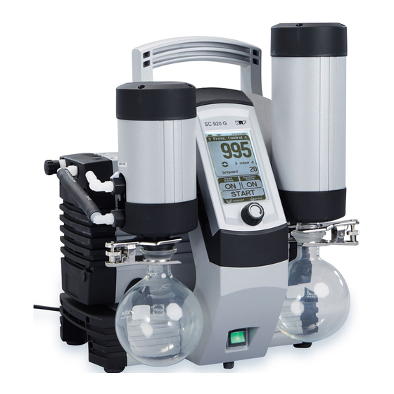
SC 920G
Advertisement
Table of Contents

Related Manuals for KNF SC 920G


Summary of Contents for KNF SC 920G
- Page 1 Operating Instructions Read and observe this Operating Instructions! Vacuum pump system with wireless remote control SC 920G KNF Neuberger GmbH Alter Weg 3 D-79112 Freiburg Germany Phone ++49 / (0)7664 / 5909-0 Fax ++49 / (0)7664 / 5909-99 E-Mail: info@knf.de www.knf.de...
- Page 2 The hand terminal is fastened in place at the factory, to prevent damage during transport. To remove the hand terminal, it is first necessary to release the transport fastener. For further details, see chapter 6. Installation and connection. Translation of original Operating Instructions, english, KNF 121308-121311 07/18...
-
Page 3: Table Of Contents
9.3. Changing Diaphragms and Valve Plates 9.4. Replace overpressure valve on high performance condenser 10. Troubleshooting 11. Ordering Information 12. Returns 13. Health and safety clearance and decontamination form Translation of original Operating Instructions, english, KNF 121308-121311 07/18... -
Page 4: About This Document
An activity to be carried out (a step) is specified here. 1. The first step of an activity to be carried out is specified here. Additional, consecutively numbered steps follow. This symbol refers to important information. Translation of original Operating Instructions, English, KNF 121308-121311 07/18... -
Page 5: Use
Vacuum Pump System SC 920G 2.1. Proper Use The SC 920G vacuum pump system is designed for use in chemical, pharmaceutical, and biological laboratories. The vacuum pump system is exclusively intended for transferring gases and vapors. Make sure that the installation location is dry and the pump/system is protected against rain, splash, hose and drip water. -
Page 6: Safety
Correct match between hand Ensure that the employees check that the hand terminal is the right terminal and vacuum pump one for this particular system before using a SC 920G vacuum system pump system. Vacuum pump systems are equipped with a paging system for this purpose (see Actuating the vacuum pump system, page 29). - Page 7 This especially applies to parts contaminated with toxic substances. Standards The vacuum pump system SC 920G conforms to the Directive 2011/65/EU (RoHS2). The vacuum pump system SC 920G conforms to the safety regulations of the EC Directive 2014/30/EU concerning Electromagnetic Compatibility and the EC Directive 2006/42/EC concerning Machinery.
-
Page 8: Technical Data
31°C, decreasing linearly to 50 % at 40°C Maximum altitude of site 2000 [m above sea level] *Liters in standard state (1,013 mbar at 0 °C) Tab. 2 (part 1) Translation of original Operating Instructions, English, KNF 121308-121311 07/18... - Page 9 100 V / 115 V / 240 V [A] Max. watt consumption [W] Protection class IP20 Fuse vacuum pump system [A] 2 x T2.5 Drive motor fusing Electronic overcurrent protection Tab. 2 (part 2) ** Automatic voltage selection Translation of original Operating Instructions, English, KNF 121308-121311 07/18...
-
Page 10: Vacuum Pump System's Hand Terminal
7 h Tab. 3 * Applies to standard included batteries When charging the hand terminals of the SC 920G vacuum pump system, use only the original power supply from KNF. Several different vacuum pump systems may be operated simultaneously with their respective hand terminals within the wireless connection range. -
Page 11: Design And Function
16 Flask clamp for 15 17 Gas outlet 18 Pin of transport fastener 19 Coolant connection on high-performance condenser (feed) 20 Coolant connection on high-performance condenser (return) Fig. 2: Vacuum pump system SC 920G Translation of original Operating Instructions, English, KNF 121308-121311 07/18... - Page 12 (for explosion protection) collection flask (Fig. 2/15). A flask clip secures the glass flask to the condenser flange. A recirculating cooler or continuously flowing cold water cools the high-performance condenser to the condensation temperature. Translation of original Operating Instructions, English, KNF 121308-121311 07/18...
-
Page 13: Vacuum Pump System Functions
Evacuation (constant vaporization rate for optimum condenser capacity utilization) Function (Following a preset pressure ramp provided in order to attain a separation from components with higher boiling points) Translation of original Operating Instructions, English, KNF 121308-121311 07/18... - Page 14 Gas ballast The gas ballast switch (Fig. 2/5) can be used to open and close the gas ballast valve on the vacuum pump system's pump (see Chapter 5.5). Translation of original Operating Instructions, English, KNF 121308-121311 07/18...
-
Page 15: Hand Terminal
The power supply also makes it possible to supply the hand termi- nal with electrical power directly from a mains connection. An acoustic alarm sounds on the hand terminal when the battery charge levels are low. Translation of original Operating Instructions, English, KNF 121308-121311 07/18... -
Page 16: Pump
The gas ballast valve is opened and closed via the gas ballast switch (see Fig. 6). Please contact KNF Service if you require an inert connection for the gas ballast. Translation of original Operating Instructions, English, KNF 121308-121311 07/18... -
Page 17: Installation And Connection
2. Pull out the pin of the transport fastener (Fig. 2/18, p. 11) as far as the limit stop. 3. Tighten the set screw again. The transport fastener can be reattached for any future transport operations. Translation of original Operating Instructions, English, KNF 121308-121311 07/18... -
Page 18: Connection
Attach coolant feed and return to high-performance condenser (Fig. 2/19 and 20, page 11). Connect only the KNF coolant valve (see Chapter 11.2, Accessories) to the coolant valve connection (Fig. 3/2, page 12). Consult with KNF before using any other valves. -
Page 19: Operation
Make sure the vacuum pump system is used properly (see chapter 2.1, page 5). Make sure the vacuum pump system is not used improperly (see chapter 2.2, page 5). Observe the safety precautions (see chapter 3, page 6). Translation of original Operating Instructions, English, KNF 121308-121311 07/18... - Page 20 Personal injury caused by poisoning or explosion and damage to the vacuum pump system. Make sure that no reactive or explosive mixtures will be produced when ventilating the vacuum WARNING pump system through the air inlet. Translation of original Operating Instructions, English, KNF 121308-121311 07/18...
- Page 21 During operation as well, there may be no overpressure in the pneumatic lines. If a pump starts against pressure, it may block. This activates the thermal switch, and the pump switches off. Translation of original Operating Instructions, English, KNF 121308-121311 07/18...
-
Page 22: Taking System Out Of Operation
If the hand terminal is switched off while the vacuum WARNING pump system remains switched on, the vacuum pump system will continue to operate with the cur- rent settings. Always switch the vacuum pump system off when done working. Translation of original Operating Instructions, English, KNF 121308-121311 07/18... -
Page 23: Operating Vacuum Pump System
Operating buttons (Fig. 9, page 25) with the following func- tions: − Start and stop the process; − open and close the ventilation valve; − open and close the high-performance condenser's coolant valve (accessory). Removing and replacing the hand terminal Translation of original Operating Instructions, English, KNF 121308-121311 07/18... - Page 24 Only in Automatic operating mode Automatic with pressure reduction Only in Automatic operating mode Automatic pressure reduction active Fig. 8: Display on the touchscreen Translation of original Operating Instructions, English, KNF 121308-121311 07/18...
-
Page 25: Operation
Pressure units can be changed only when no process is active. In order to change the unit of pressure, it is necessary to temporarily switch to another operating mode. Fig. 10: Pressure units menu Translation of original Operating Instructions, English, KNF 121308-121311 07/18... - Page 26 Press on the rotary/push knob: Vacuum pump system will evacuate. Let go: Actual pressure will be adopted as setpoint pressure. Rotate: Changes setpoint pressure. Fig. 11: Operating mode menu Translation of original Operating Instructions, English, KNF 121308-121311 07/18...
- Page 27 If a boiling point is detected in Automatic mode, after the system regulates to this pressure, the pressure is reduced automatically to speed up evaporation of the solvent (see Fig. 12). Translation of original Operating Instructions, English, KNF 121308-121311 07/18...
- Page 28 The desired pressure curve is entered via data points that connect the vacuum pump system to pressure ramps. Fig. 13: Menu for Function operating mode Entering data points (up to 12): Time interval since the last data point: ∆ t Translation of original Operating Instructions, English, KNF 121308-121311 07/18...
- Page 29 = Repetition. The desired number of repetitions can now be specified in the field for the setpoint pressure. … = Deletion of the data point. In both cases, all subsequent sampling points are automatically deleted. Translation of original Operating Instructions, English, KNF 121308-121311 07/18...
- Page 30 An audible warning will be emitted if a button on the touch- screen is pressed. Refer to chapter 10, table 9 for tips on resolving this problem. Fig. 14: Display „No connection“ Translation of original Operating Instructions, English, KNF 121308-121311 07/18...
-
Page 31: Changing Batteries On The Hand Terminal
Refer to chapter 4.2, page 10, for required battery specifica- tions. Never use new and used batteries together. Batteries must always be replaced all at the same time. Re-install cover plate. Dispose of batteries according to regulations. Translation of original Operating Instructions, English, KNF 121308-121311 07/18... -
Page 32: Operation Without Hand Terminal
(accessory) on the high-performance condenser Fig. 15: Buttons on vacuum pump system 8.3. Software Please see the delivered CD for information on operating the vacuum pump system via software. Translation of original Operating Instructions, English, KNF 121308-121311 07/18... -
Page 33: Servicing
Grasp the collection flask (Fig. 2/12, page 11) and simulta- neously remove attachment clamp 11; pull out collection flask. Dispose of contents in collection flask according to local regu- lations. Then rinse out collection flask. Reattach collection flask. Translation of original Operating Instructions, English, KNF 121308-121311 07/18... - Page 34 Grasp the collection flask (Fig. 2/15, page 11) and simulta- neously remove attachment clamp 16; pull out collection flask. Dispose of contents in collection flask according to local regu- lations. Then rinse out collection flask. Reattach collection flask. Translation of original Operating Instructions, English, KNF 121308-121311 07/18...
-
Page 35: Changing Diaphragms And Valve Plates
3. Undo two screws (6) each, and remove both covers (5) at head cover (4). 4. Lift the head cover (3) off the pump housing (17). 5. Lift off head plate (9) with intermediate plates (10), (13) and (14). Translation of original Operating Instructions, English, KNF 121308-121311 07/18... - Page 36 Before you finally tighten the diaphragm, you are recommended to move the diaphragm to the upper dead center by rotating the fan (19). 3. Put head plate (9) with intermediate plates (10), (13) and (14) on adapter (16). Translation of original Operating Instructions, English, KNF 121308-121311 07/18...
- Page 37 (see step 1). Remount the covers (4). Tighten the two screws (1) on the head cover (tightening torque: 5 Nm). Translation of original Operating Instructions, English, KNF 121308-121311 07/18...
- Page 38 Servicing Vacuum Pump System SC 920G Final steps Reconnect vacuum pump system tubing. Reconnect vacuum pump system to the electricity supply. Translation of original Operating Instructions, English, KNF 121308-121311 07/18...
-
Page 39: Replace Overpressure Valve On High Performance Condenser
2. Detach the old overpressure valve from screw socket of high performance condenser. 3. Slide on the new overpressure valve. Be aware that the overpressure port is completely covered. 4. Reconnect high performance condenser with pump. Translation of original Operating Instructions, English, KNF 121308-121311 07/18... -
Page 40: Troubleshooting
Replace any leaky hoses. Replace any damaged hose nipples. For ordering numbers see chapter 11, page 45. Carefully tighten hexagonal gland Hexagonal gland (Fig. 2/8, p. 12) loose. with wrench. Translation of original Operating Instructions, English, KNF 121308-121311 07/18... - Page 41 36) in diagonally opposite sequence. Make connection. Pump not activated on Hand terminal or software process start-up, in spite of not connected to vacuum pressure decrease command. pump system. Translation of original Operating Instructions, English, KNF 121308-121311 07/18...
- Page 42 The hand terminal is tone sounds. designed for use with a the vaccum pump system, p. 29) to different SC 920G vacuum check whether the right hand termi- pump system. nal is being used. Translation of original Operating Instructions, English, KNF 121308-121311 07/18...
- Page 43 See Tab. 8, "Required vacuum not Leaks in system. generated even though pump is running”. Contact KNF Service. Recalibration of pressure sensor required. Tab. 8 Translation of original Operating Instructions, English, KNF 121308-121311 07/18...
- Page 44 Fault cannot be rectified If you are unable to determine any of the specified causes, send the vacuum pump system to KNF Customer Service (see last page for the address). 1. Flush the vacuum pump system to free the pump head, tubing and glas vessels of dangerous or aggressive gases (see chapter 9.2.1, page 33).
-
Page 45: Ordering Information
Collection flask 500 ml (coated) 047729 Flask clamp 025968 Fuse T 2.5 027575 Allen key 2.0 for transport fastener 117432 Tab. 11 * Please specify the required length (in whole meters) Translation of original Operating Instructions, English, KNF 121308-121311 07/18... - Page 46 Wall fixture hand terminal 120130 Tripod fixture hand terminal 120132 Tab. 12 * For situations in which several SC 920G vacuum pump systems are operated within the wireless connection range. Translation of original Operating Instructions, English, KNF 121308-121311 07/18...
-
Page 47: Returns
For optimal processing of a return, a copy of this declaration should be sent in advance via e-mail, regular mail, or fax to KNF Customer Service (refer to final page for address). In order to avoid endangering employees who open the shipment's packaging,... -
Page 48: Health And Safety Clearance And Decontamination Form
Health and safety clearance and decontamination form Vacuum Pump System SC 920G 13. Health and safety clearance and decontamination form KNF worldwide Find your local KNF partner on www.knf.com...
Need help?
Do you have a question about the SC 920G and is the answer not in the manual?
Questions and answers