Advertisement
Quick Links
INETS-IOEX-DOOR-BATT
Door Sensor
Installation Guide
Description
The Crestron
®
INETS-IOEX-DOOR-BATT door sensor detects when a door is open
or closed and transmits the state to the Crestron control system. The door sensor
communicates with the control system via the infiNET EX
sensor is comprised of two parts: a magnet and a sensor.
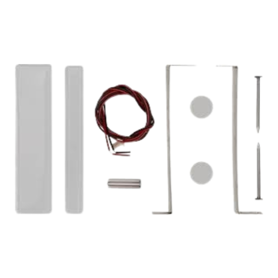
Parts that are included with the INETS-IOEX-DOOR-BATT:
Sensor
Encapsulated magnet - 11/16 in. x 2-11/16 in.
Disc magnet - 1/2 in. Dia. x 1/16 in. L
Barrel magnet - 15/64 in. Dia. x 25/32 in. L
Double-sided tape - 1/2 in. Dia.
Nail - 1 in.
Mounting bracket
Dry contact connector
Paper Clip (Attached to Installation Guide)
Additional Resources
Visit the product page on the Crestron website (www.crestron.com) for
additional information and the latest firmware updates. Click the QR
code or use a QR reader application on your mobile device to scan the
QR image.
Install the Door Sensor
The sensor can be recess mounted by placing it into a drilled hole in the top of the door or
surface mounted by using double-sided tape to adhere it to the face of the door.
To ensure proper operation, the active end of the sensor must be in close proximity to
the magnet. The active end of the sensor has a hole for the setup button and a notch for
removing the bottom cover.
NOTES:
• The INETS-IOEX-DOOR-BATT must be installed within range of an infiNET EX
wireless network.
• If installed in a hard-to-reach location, join the infiNET EX wireless network
before installation. Refer to the "Operation" section on page 2 for details.
Recess Mount the Sensor
Install the sensor into the top of the door near the strike edge to keep the sensor hidden
from view.
NOTE: If necessary, the sensor can be installed in the door frame jamb and the magnet
may be secured to the door.
Install the Sensor
1. Use a drill and a 7/8 in. diameter drill bit to make a 2-11/16 in. (68 mm) deep hole in
the top of the door. The hole should be centered in the top of the door near the strike
edge (latch side). Ensure that the hole is straight to prevent binding.
Top of door
wireless network. The door
®
ITEM
Drill a 7/8 in. diameter,
2-11/16 in. (68 mm) deep
mounting hole.
Strike edge of door (latch side)
Door face
2. Remove one side of the preinstalled double-sided tape from a mounting bracket
and then secure the mounting bracket to the side of the sensor. When securing the
bracket to the sensor, ensure that the tabs on the mounting bracket face away from
the active end of the sensor. Repeat for the other mounting bracket.
Qty
1
1
The mounting bracket tabs
1
must face away from the
active end of the sensor.
1
3. Insert the sensor and bracket assembly into the hole.
1
4. Secure the sensor and bracket assembly using two nails (supplied).
2
Insert the sensor into the
2
door and secure with nails.
1
1
Install the Disc or Barrel Magnet
Place a disc or barrel magnet on the door frame opposite the active end of the sensor. The
distance between the active end of the sensor and the magnet should be 1/8 in. or less.
NOTE: To ensure proper operation, a recess may need to be made in the door frame to
maintain proper distance between the magnet and the door sensor.
Install the magnet:
1. Remove one side of the double-sided tape and place it onto a flat side of the
magnet.
2. Remove the other side of the double-sided tape and secure the magnet to the door
frame.
Surface Mount the Sensor
Secure the sensor to the face of the door. The sensor should be located at the top of the
door so that it is near the door jamb and strike edge. The sensor can be installed vertically
or horizontally on the face of the door.
NOTE: If necessary, the sensor can be secured to the door frame jamb and the magnet
may be secured to the door.
Install the Sensor
1. Remove one side of the double sided tape from the sensor.
2. Secure the sensor to the face of the door.
Top of door
Install the Encapsulated Magnet
The encapsulated magnet should be placed on the door frame with the marked "M" on
the magnet adjacent to the active end of the sensor. The encapsulated magnet should be
parallel to the sensor and placed 1/8 in. from the sensor when the door is closed.
NOTE: If necessary, the magnet end can be determined by moving the case of the
encapsulated magnet near a ferrous metal object.
Install the encapsulated magnet:
1. Remove one side of the double sided tape from the encapsulated magnet.
2. Secure the encapsulated magnet to the door frame.
Active end
of sensor
Strike edge of door
(latch side)
Door swing
Place sensor here
Strike edge of door (latch side)
Door face
Advertisement

Subscribe to Our Youtube Channel
Related Manuals for Crestron INETS-IOEX-DOOR-BATT


Summary of Contents for Crestron INETS-IOEX-DOOR-BATT
- Page 1 Crestron control system. The door sensor the active end of the sensor. Repeat for the other mounting bracket.
- Page 2 4. Replace the bottom cover. To check the communications status of the door sensor, send the VER command using the Crestron Toolbox console and then open or close the door (or press the setup button). The Specifications Crestron Toolbox console will provide the communications status.
Need help?
Do you have a question about the INETS-IOEX-DOOR-BATT and is the answer not in the manual?
Questions and answers