
Related Manuals for Ingersol Rand LC2A Series

Summary of Contents for Ingersol Rand LC2A Series
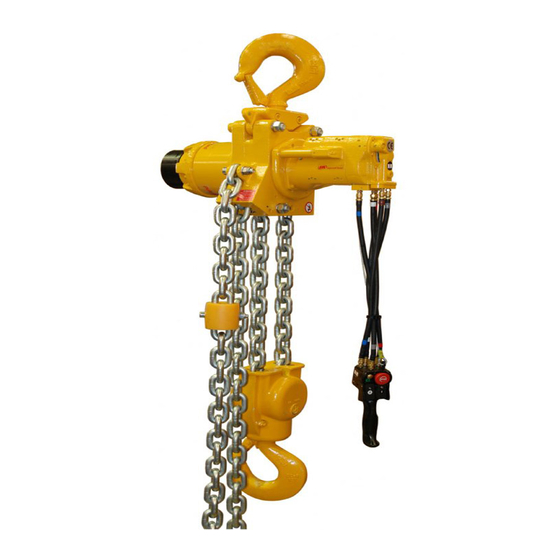
- Page 1 Product Information LOW HEADROOM AIR CHAIN HOIST Models LC2A060S, LC2A120D, LC2A180T and LC2A250Q Save These Instructions Form MHD56469 Edition 1 November 2010 45926003 2010 Ingersoll-Rand Company ©...
-
Page 2: Product Description
Only allow trained technicians to perform maintenance on this product. For additional information contact factory or nearest Ingersoll Rand Ingersoll Rand Distributor. For additional supporting documentation refer to Table 1 ‘Product Information Manuals’ on page 2. Manuals can be downloaded from www.ingersollrandproducts.com. The use of other than genuine Ingersoll Rand replacement parts may result in safety hazards, decreased performance and increased maintenance and will invalidate all warranties. -
Page 3: Specifications
SPECIFICATIONS Model Code Explanation Example: LC2A060SIP3LRE3M2A-E LC2A060S Low Headroom Air Hoist Capacity and Chain Falls LC2A060S 6000 kg (13,200 lbs), single fall LC2A120D 12,000 kg (26,500 lbs), two fall LC2A180T 18,000 kg (39,700 lbs), three fall LC2A250Q 25,000 kg (55,000 lbs), four fall Application Industrial Control Type... -
Page 4: Capacity Information
Table 2: Specifications Sound Air Inlet Air Consumption Weight of Chain Unit Net Weight with Chain Size Pressure Rated Capacity Load Size @ Rated Load per meter of lift Standard 10 ft (3 m) Lift Hoist Model Level * metric tons Chain Falls scfm m³/min... -
Page 5: Air Supply
Rack segments should be installed on the outside edge of the lower flange of the Trolley Installation Over the Open End of the Beam trolley beam. Allow 1/4 inch (6.5 mm) clearance between the edge of the lower flange and rack segment for fillet weld. The rack segments should be clamped tight against Pre-adjust trolley for installation using Dwg. -
Page 6: Operation
1. Give the hoist an inspection conforming to the requirements of ’Hoists Not in NOTICE Regular Use’ in the ’INSPECTION’ section on page 7. 2. Inject a small amount of ISO VG 32 (SAE 10W) oil in the motor inlet port. 3. -
Page 7: Frequent Inspection
INSPECTION 1. Check hoist for oil leaks daily. Immediately repair any leaks. WARNING 2. At the beginning of each shift operate the hoist in both directions without a load. Ensure the motor runs free, and that the brake(s) do not drag. •... -
Page 8: General Lubrication
LUBRICATION To ensure continued satisfactory operation of hoist, all points requiring lubrication must be serviced with correct lubricant at proper time interval as indicated for each n Load Chain assembly. WARNING Refer to ‘Maintenance Interval’ chart in Product Maintenance Information Manual for recommended lubrication intervals. -
Page 9: Warranty
18 and 25 ton n Trolley Reduction Gearbox Refer to Dwg. MHP3072 on page 12, A. Fill Plug; B. Drain Plug. 6 and 12 ton To Drain The reduction gearbox is shipped from the factory with the correct amount of grease. 1. -
Page 10: Product Information Graphics
PRODUCT INFORMATION GRAPHICS AIR DRIVEN TROLLEY P= 5 to 7 bar CHAIN HOIST TOP LIMIT SWITCH Fitting 95230151 REAR VIEW OF MOTOR FROM TROLLEY (left) (up) (down) (right) PHS4D-U PENDANT CONTROL STOP C (Air Supply) D (Down) COLOR CODE B (On) (A)-Blue (B)-Grey (C)-White... - Page 11 PRODUCT INFORMATION GRAPHICS CONTINUED Air Out Regulator Air In Lubricator Filter (Dwg. MHP0111) (Dwg. MHP0191) Emergency “ON” Stop Button Button (Dwg. MHP0102) Trolley Control Levers Pendant Hoist Handle Control Levers (Dwg. MHP1547) (Dwg. MHP1300) Throat Width (Dwg. MHP0040) Form MHD56469 Edition 1...
- Page 12 PRODUCT INFORMATION GRAPHICS CONTINUED Fill Plug (Not to scale) 6 inches (152 mm) Stagger welds along rack Check clearance 6 inches between racks (152 mm) 0.08” (2 mm) Use rack guide for correct track positioning Drain Plug (Dwg. MHP3072) (Dwg. MHP3016) Rack Hoist Trolley Drive Assembly...
- Page 13 Hoist adapter Spacers equal on both centered under sides of hoist adapter I-Beam and side plates Wheel Beam Clearance 0.09-0.15 in (2-4mm) (Dwg. MHP1537) Fill Plug Drain Plug Oil Level Plug (Dwg. MHP3162) Form MHD56469 Edition 1...
-
Page 14: Service Notes
SERVICE NOTES Form MHD56469 Edition 1... - Page 15 DECLARATION OF CONFORMITY (CS) PROHLÁŠENÍ O SHODĚ (DA) OVERENSSTEMMELSESERKLÆRING (DE) KONFORMITÄTSERKLÄRUNG (EL) ∆ΗΛΩΣΗ ΑΝΑΓΝΩΡΙΣΗΣ (ES) DECLARACIÓN DE CONFORMIDAD (FI) VAKUUTUS NORMIEN TÄYTTÄMISESTÄ (FR) CERTIFICAT DE CONFORMITÉ (HU) MEGFELELŐSÉGI NYILATKOZAT (IT) DICHIARAZIONE DI CONFORMITÀ (LT) ATBILSTĪBAS DEKLARĀCIJA (LV) ATITIKTIES DEKLARACIJA (NL) SCHRIFTELIJKE VERKLARING VAN CONFORMITEIT (NO) KONFORMITETSERKLÆRING (PT) DECLARAÇÃO DE CONFORMIDADE (PL) DEKLARACJA ZGODNOŚCI (SK) PREHLÁSENIE O ZHODE (SL) IZJAVA O SKLADNOSTI...
- Page 16 www.ingersollrandproducts.com...
Need help?
Do you have a question about the LC2A Series and is the answer not in the manual?
Questions and answers