Advertisement
Quick Links
v1.2018.01.15
Also watch our assembly video
found on www.alfratools.com
Any user or installer of this assembly table must study this instruction manual carefully. If this table is sold,
please provide the manual to the buyer, installers, or support personnel assembling the product.
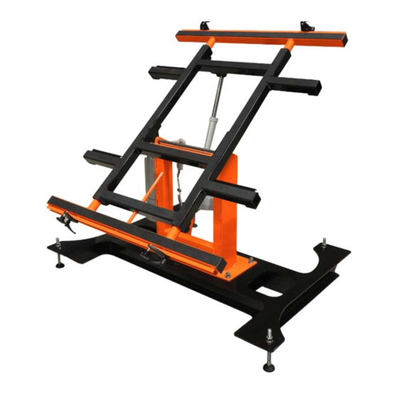
AMTE 300
ELECTRIC ASSEMBLY TABLE
ASSEMBLY
INSTRUCTIONS
SAVE THESE INSTRUCTIONS:
Advertisement

Related Manuals for ALFRA AMTE 300


Summary of Contents for ALFRA AMTE 300
- Page 1 AMTE 300 ELECTRIC ASSEMBLY TABLE v1.2018.01.15 ASSEMBLY INSTRUCTIONS Also watch our assembly video found on www.alfratools.com SAVE THESE INSTRUCTIONS: Any user or installer of this assembly table must study this instruction manual carefully. If this table is sold, please provide the manual to the buyer, installers, or support personnel assembling the product.
- Page 2 AMTE-300 ASSEMBLY MANUAL W W W. A L F R ATO O L S . CO M | 847 - 84 4 - 89 00 | V 1.2 01 8.01 .15...
- Page 3 AMTE-300 ASSEMBLY MANUAL TABLE OF CONTENTS SAFETY PRECAUTIONS TOOLS REQUIRED HARDWARE INCLUDED HARDWARE PLACEMENTS ASSEMBLY INSTRUCTIONS W W W. A L F R ATO O L S . CO M | 847 - 84 4 - 89 00 | V 1.2 01 8.01 .15...
-
Page 4: Safety Precautions
AMTE-300 ASSEMBLY MANUAL SAFETY PRECAUTIONS Safety is essential to the use and maintenance of ALFRA tools and equipment. This assembly manual and any markings on the tool provide information for avoiding hazards and unsafe practices related to the use of this tool. -
Page 5: Tools Required
AMTE-300 ASSEMBLY MANUAL TOOLS REQUIRED PLIERS WRENCH SOFT HEADED HAMMER LE VEL BALL ALLEN PEEN WRENCH HAMMER (4MM) W W W. A L F R ATO O L S . CO M | 847 - 84 4 - 89 00 | V 1.2 01 8.01 .15... -
Page 6: Hardware Included
AMTE-300 ASSEMBLY MANUAL HARDWARE INCLUDED ITEM PART NUMBER DESCRIPTION 31003-100 Base Frame 31003-106 Middle Support 31003-114 Table Top 31003-124 Lower Extension 31003-123 Upper Extension 31003-127-L Clamping Unit Standard - Left Hand 31003-127-R Clamping Unit Standard - Right Hand 31003-006 Bolt with pad M16 x 150 mm Leveling Pad 31003-117 Actuator 31003-002... - Page 7 AMTE-300 ASSEMBLY MANUAL W W W. A L F R ATO O L S . CO M | 847 - 84 4 - 89 00 | V 1.2 01 8.01 .15...
-
Page 8: Hardware Placement
AMTE-300 ASSEMBLY MANUAL HARDWARE PLACEMENT W W W. A L F R ATO O L S . CO M | 847 - 84 4 - 89 00 | V 1.2 01 8.01 .15... - Page 9 AMTE-300 ASSEMBLY MANUAL ASSEMBLY INSTRUCTIONS Place the base frame on a wooden pallet or other raised platform so that it is raised off of the ground. F I G U R E 1 Thread hex nut onto assembled leveling pad about half way down shaft.
- Page 10 AMTE-300 ASSEMBLY MANUAL Position assembled leveling pad underneath corner of base frame and insert through center hole. Place flat washer onto the bolt of leveling pad over the top side of base frame followed by lock washer Loosely thread hex nut over flat washer .
- Page 11 AMTE-300 ASSEMBLY MANUAL Place the middle support on to center of base frame aligning the bolts on base frame with holes on middle support . The mount for the actuator on middle support (see figure 5) should be facing the rear of the table. (See figure 6) Once positioned, place flat washer onto bolts of base frame followed by lock washer...
- Page 12 AMTE-300 ASSEMBLY MANUAL On right side of middle support (when standing at the rear of the table) place and hold controller while aligning the three screw holes. Take button head cap screw and secure tightly into side of middle support and controller using an allen wrench.
- Page 13 AMTE-300 ASSEMBLY MANUAL With the actuator shaft pointing downward, align bottom hinge of actuator and the actuator mount located on the middle support together. Slide flanged pin through both units, insert cotter pin and secure with pliers. W W W. A L F R ATO O L S . CO M | 847 - 84 4 - 89 00 | V 1.2 01 8.01 .15...
- Page 14 AMTE-300 ASSEMBLY MANUAL Align center mounting hinges of table top with top holes on middle support . Felted surface of table top should be positioned upwards. (See figure 11) Slide hinge connecting rod through both the table top hinges and the middle support .
- Page 15 AMTE-300 ASSEMBLY MANUAL Rotate actuator so that shaft is pointing upwards. Tilt table top align mounting hinge on table top3 with the very end of the actuator shaft. Slide flanged pin through both units, insert cotter pin secure with pliers. F I G U R E 1 2 Using a soft head hammer, insert the square tubing plug...
- Page 16 AMTE-300 ASSEMBLY MANUAL F I G U R E 1 4 Hang 2 button keypad on hook of middle support . Plug actuator power cord and cord of 2 button keypad into controller Install battery into controller sliding battery on top and firmly pressing on handle until it clicks into place.
- Page 17 AMTE-300 ASSEMBLY MANUAL Using the 2 button keypad , bring the table top into horizontal position and adjust the extension positions as needed to accommodate the panel you will be working Before adjusting the lower extension , remove the quick release pin inserted into the safety splinter.
- Page 18 AMTE-300 ASSEMBLY MANUAL Install clamping units on upper and lower extensions by aligning rectangle nut and 6&7 4&5 stud with the uni-rail. Once in position, tighten quick release lever on clamping units 6&7 F I G U R E 1 8 BEFORE INITIAL OPERATION Charge battery with power supply...
Need help?
Do you have a question about the AMTE 300 and is the answer not in the manual?
Questions and answers