Advertisement
Quick Links
EN1501 Pulse Meter Transmitter and
EN1501-XL Pulse Meter Transmitter with
Extended Life
Installation Instructions
1 Overview
Connected to pulse-output meters being used for multi-family submetering,
the EN1501 pulse meter transmitter and EN1501-XL pulse meter
transmitter with extended life will transmit data to an RF gateway. The
EN1501 includes a replaceable battery; the EN1501-XL includes a long-life
battery that is not replaceable.
1.1 Inovonics Contact Information
For product and installation videos visit us at
www.inovonics.com/videos or use the QR
code below.
If you have any problems with this procedure, contact Inovonics Wireless
technical services:
• E-mail: support@inovonics.com.
• Phone: (800) 782-2709.
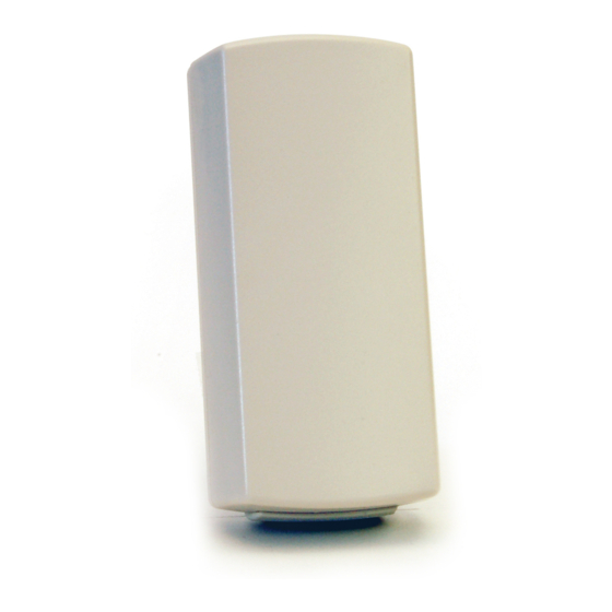
1.2 EN1501/EN1501-XL Components
A
Figure 1 EN1501/EN1501-XL Components
A Battery (EN1501-
B Tamper switch
style battery shown)
D Reset button
1.3 What's In The Carton
• Fifty drywall anchors.
• Fifty mounting screws.
• Fifty pieces of mounting tape.
7.24.19 357-04590-02 Rev A © Inovonics, 2019 - www.inovonics.com
B
C
D
C Removable header
terminal
2 Installation and Startup
2.1 Installation Notes
• These products are designed to be maintained by professional
technicians.
• Products are tested for indoor use.
2.2 Input Requirements
The EN1501 and EN1501-XL require the following input specifications for
compatibility with the meter:
• A dry contact such as a reed switch.
• The pulse width of a switch output when it is activated must be greater
than or equal to 10ms.
• A maximum rate of six pulses per second.
• Closed impedance of the pulser mechanism must be smaller than 1k
ohm.
• Open impedance of the pulser mechanism must be greater than five
megohms.
2.3 Connect Transmitter to Meter
Connect the transmitter to the meter as follows:
1. Open the housing by pressing down on the base tab near the wiring
through-hole while lifting away the cover.
2. Fully insert stripped wires into the removable header terminal.
3. Use a small Phillips screwdriver to tighten the screws that secure wires
to the removable header terminal.
4. Attach removable header terminal (if removed) to the transmitter board
as shown.
Note: If connecting to a meter that has polarity to its pulse output, the
negative (–) should be connected to the outside terminal, closest to the
corner of the board.
A
B
Figure 2 Connect the Transmitter to the Meter
A Cabling through-hole
2.4 Mount the Transmitter
1. Use the double-sided tape to mount the transmitter to a clean wall.
2. As desired, secure the transmitter to the wall with the mounting screw
and anchor.
Note: To secure the EN1501, you will need to remove the battery to access
the mounting screw hole. Make sure to press the reset button after
replacing the battery to initialize the transmitter.
B Removable header terminal
Advertisement

Subscribe to Our Youtube Channel
Related Manuals for Inovonics EN1501


Summary of Contents for Inovonics EN1501
- Page 1 2. As desired, secure the transmitter to the wall with the mounting screw and anchor. 1.3 What’s In The Carton Note: To secure the EN1501, you will need to remove the battery to access • Fifty drywall anchors. the mounting screw hole. Make sure to press the reset button after •...
-
Page 2: Specifications
Operating environment: -20°- 60°C (-4°- 140°F), 90% relative humidity, non-condensing Typical battery life: EN1501: 10 year battery life in a climate controlled environment with the specified Panasonic CR123A battery; EN1501-XL: calculated battery life of 20 years at 70 to 90°F (20 to 30°C). Higher temperatures reduce battery life.
Need help?
Do you have a question about the EN1501 and is the answer not in the manual?
Questions and answers