Table of Contents
Advertisement
Quick Links
Advertisement
Table of Contents

Subscribe to Our Youtube Channel
Related Manuals for Arbor Technology Qseven EmQ-i2401


Summary of Contents for Arbor Technology Qseven EmQ-i2401
- Page 1 EmQ-i2401 Qseven® CPU Module User’s Manual Version 1.1 2019.07...
- Page 2 This page is intentionally left blank. - II -...
-
Page 3: Revision History
Revision History Version Release Time Description 2017.06 Initial release 2019.07 1.4. Inside the Package Remove Driver CD from the package. 1.5. Ordering Information: Revise memory from 8G to 4G. 1.6. Driver Installation Note: Revise installation description. - i -... -
Page 4: Table Of Contents
Contents Contents Revision History .................i Contents .....................ii Preface....................iv Copyright Notice ..................iv Declaration of Conformity ..............iv CE ....................iv FCC Class B ..................v RoHS ....................v SVHC / REACH ................vi Warning ....................vi Replacing the Lithium Battery ..............vi Technical Support .................. -
Page 5: Contents
Contents 3.3.4 SATA Drives ................28 3.3.5 SCC Configuration ..............29 3.3.6 USB Configuration ..............29 3.4 Security ..................30 3.5 Boot ....................31 Appendices ..................33 Appendix A. I/O Port Address Map ............34 Appendix B. Interrupt Request Lines (IRQ) .......... 35 Appendix C. -
Page 6: Preface
Preface Preface Copyright Notice All Rights Reserved. The information in this document is subject to change without prior notice in order to improve the reliability, design and function. It does not represent a commitment on the part of the manufacturer. Under no circumstances will the manufacturer be liable for any direct, indirect, special, incidental, or consequential damages arising from the use or inability to use the product or documentation, even if advised of the possibility of such... -
Page 7: Fcc Class B
RoHS ARBOR Technology Corp. certifies that all components in its products are in compliance and conform to the European Union’s Restriction of Use of Haz- ardous Substances in Electrical and Electronic Equipment (RoHS) Directive 2002/95/EC. -
Page 8: Svhc / Reach
Preface SVHC / REACH To minimize the environmental impact and take more responsibility to the earth we live, Arbor hereby confirms all products comply with the restriction of SVHC (Substances of Very High Concern) in (EC) 1907/2006 (REACH --Registration, Evaluation, Authorization, and Restriction of Chemicals) regulated by the European Union. -
Page 9: Warranty
Preface Warranty This product is warranted to be in good working order for a period of two years from the date of purchase. Should this product fail to be in good working order at any time during this period, we will, at our option, replace or repair it at no additional charge except as set forth in the following terms. - Page 10 This page is intentionally left blank. - viii -...
-
Page 11: Chapter 1 Introduction
Chapter 1 Introduction Chapter 1 - Introduction - 1 -... -
Page 12: The Product
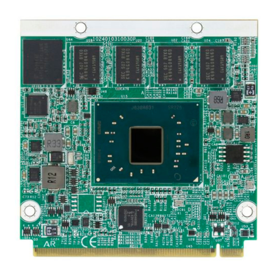
Introduction 1.1. The Product • Soldered onboard Intel Apollolake SoC Processor • Intergrated Gigabit Ethernet • Dual Channel 24-bit LVDS and 1 x DDI port • Anti-crash for automatically system BIOS recovering 1.2. About this Manual This manual is intended for experienced users and integrators with hardware knowledge of computers. -
Page 13: Specifications
Introduction 1.3. Specifications Form Factor Qseven CPU Module ® Soldered onboard Intel Celeron® N3350 2.4GHz processor/ Intel Pentium® N4200 2.5GHz processor Soldered onboard 8x512Mbx8 chips for supporting DDR3L System Memory 4GB memory capacity, upgradable to 8GB BIOS AMI BIOS, UEFI Code 4 x USB 2.0 ports 2 x USB 3.0 SuperSpeed ports Expansion Bus... -
Page 14: Inside The Package
Introduction 1.4. Inside the Package Before starting with the installation, make sure the following items are shipped. If any of the items is missing or appears damaged, contact your local dealer or distributor. 1 x EmQ-i2401 Qseven® CPU Module 1 x Quick Installation Guide 1.5. -
Page 15: Driver Installation Note
Introduction 1.6. Driver Installation Note The CPU module supports Windows 10. To install the drivers, please visit our website at www.arbor-technology.com and download the driver pack from the product page. If you need driver DVD, please contact your ARBOR sales repre- sentative. - Page 16 This page is intentionally left blank. - 6 -...
-
Page 17: Chapter 2 Board Overview
Chapter 2 Board Overview Chapter 2 - Board Overview - 7 -... -
Page 18: Board Dimensions
Board Overview 2.1. Board Dimensions - 8 -... -
Page 19: Block Diagram
Board Overview 2.2. Block Diagram Onboard DDR3L DDR3L-1867MT/s, upgradable to 8GB 4GB SDRAM Dual Channel 24-bit LVDS PTN3460 1 x DP (DDI0) 4 x PCIex1 2 x USB 2.0 host ports 2 x USB 3.0/ 2.0 host ports Intel® SATA0, 1 6GB/s ports Pentium N4200 Celeron N3350 HD Audio Link... -
Page 20: Connector Pin Definition
Board Overview 2.3. Connector Pin Definition Pin Signal Pin Signal Pin Signal Pin Signal Q7_AZ_SDATA_IN I2C_CLK0 LAN1_MDI3- LAN1_MDI2- I2C_DATA0 Q7_AZ_SDATA_OUT LAN1_MDI3+ LAN1_MDI2+ THRM# WDTRIG# THRMTRIP# WDOUT LAN_LINK100# LAN_LINK_1000# LAN1_MDI1- LAN1_MDI0- USB3TXN0 USB3_RXN0 LAN1_MDI1+ LAN1_MDI0+ USB3TXP0 USB3_RXP0 LED_LINK# LAN_ACT# USB_6_7_OC# (N/C) USB_4_5_OC#(N/C) SLP_S4# GBE_CTREF (N/C) - Page 21 Board Overview Pin Signal Pin Signal Pin Signal Pin Signal 131 Q7_DDI0_TXP3 132 RSVD (N/C) 197 GND 198 GND 133 Q7_DDI0_TXN3 134 RSVD (N/C) 199 Q7_SPI_MOSI 200 Q7_SPI_CS#0 135 GND 136 GND 201 Q7_SPI_MISO 202 Q7_SPI_CS#1 137 Q7_DDI0_TXP1 138 DDI0_AUXP 203 Q7_SPI_CLK 204 MFG_NC4 (N/C) 139 Q7_DDI0_TXN1...
- Page 22 This page is intentionally left blank. - 12 -...
-
Page 23: Chapter 3 - Bios
Chapter 3 BIOS Chapter 3 - BIOS - 13 -... - Page 24 BIOS The BIOS Setup utility is featured by AMI BIOS to configure the system settings stored in the system’s BIOS ROM. AMI BIOS is activated once the computer powers on. After entering the utility, use the left/right arrow keys to navigate between the top menus and use the down arrow key to access one.
-
Page 25: Main
BIOS 3.1 Main The AMI BIOS provides a Setup utility program for specifying the system configurations and settings. The BIOS RAM of the system stores the Setup utility and configurations. When you turn on the computer, the AMI BIOS is immediately activated. - Page 26 BIOS Key Commands BIOS Setup Utility is mainly a key-based navigation interface. Please refer to the following key command instructions for navigation process. Keystroke Function Move to highlight a particular configuration screen from ◄ ► the top menu bar / Move to highlight items on the screen ▼...
-
Page 27: Advanced
BIOS 3.2 Advanced The “Advanced” setting page provides you the options to configure the details of your hardware, such as ACPI, CPU, SATA, AMT, USB and Super IO. Aptio Setup Utility - Copyright (C) 2016 American Megatrends, Inc. Main Advanced Chipset Security Boot... -
Page 28: Acpi Settings
BIOS 3.2.1 ACPI Settings Aptio Setup Utility - Copyright (C) 2012 American Megatrends, Inc. Aptio Setup Utility - Copyright (C) 2016 American Megatrends, Inc. Advanced ACPI Settings Enables or Disables System ability to Enable Hibernation [Enabled] hibernate (OS/S4 Sleep ACPI Sleep State State). -
Page 29: F81899 Super Io Configuration
BIOS 3.2.2 F81899 Super IO Configuration Aptio Setup Utility - Copyright (C) 2012 American Megatrends, Inc. Aptio Setup Utility - Copyright (C) 2016 American Megatrends, Inc. Advanced Super IO Configuration Set Parameters of Serial Port 1 (COMA) Super IO Chip F81866 ►... -
Page 30: Hardware Monitor
BIOS 3.2.3 Hardware Monitor Aptio Setup Utility - Copyright (C) 2012 American Megatrends, Inc. Aptio Setup Utility - Copyright (C) 2016 American Megatrends, Inc. Advanced Pc Health Status CPU Temperature : +39˚C System Temperature : +40˚C Fan1 Speed : N/A +3.3S : +3.344 V +V5A... -
Page 31: Cpu Configuration
BIOS 3.2.4 CPU Configuration Access this submenu to configure the CPU features. Aptio Setup Utility - Copyright (C) 2016 American Megatrends, Inc. Advanced CPU Configuration Socket specific CPU Information Socket 0 CPU Information CPU Speed 1600 MHz 64-bit Supported Limit CPUID Maximum [Disabled] Bi-directional PROCHOT [Enabled]... -
Page 32: Csm Configuration
BIOS 3.2.5 CSM Configuration Aptio Setup Utility - Copyright (C) 2012 American Megatrends, Inc. Aptio Setup Utility - Copyright (C) 2016 American Megatrends, Inc. Advanced Compatibility Support Module Configuration Enable/Disable CSM Support. CSM Support [Enabled] CSM16 Module Version 07.79 Boot option filter [UEFI and Legacy] Option ROM execution Network... - Page 33 BIOS Control the execution of UEFI and Legacy Video OpROM. Video Options: Do not launch, UEFI and Legacy ► (default). - 23 -...
-
Page 34: Usb Configuration
BIOS 3.2.6 USB Configuration Select this submenu to view the status of the USB ports and configure USB features. Aptio Setup Utility - Copyright (C) 2016 American Megatrends, Inc. Main Advanced Chipset Boot Security Save & Exit USB Configuration Enables Legacy USB support. AUTO option disables legacy USB Module Version support if no USB devices are... - Page 35 BIOS Enables/disables the support for USB mass storage USB Mass Storage driver. Driver Support Enabled is the default. The time-out value for Control, Bulk and Interrupt USB transfer time-out transfers. Options: 1/5/10/20 sec (default) USB mass storage device Start Unit command time- Device reset time-out out.
-
Page 36: Chipset
BIOS 3.3 Chipset Aptio Setup Utility - Copyright (C) 2017 American Megatrends, Inc. Main Advanced Security Boot Save & Exit Chipset LCD Concontrol ► LCD Control ► HD-Audio Configuration ► PCI Express Configuration ► SATA Drives ► SCC Configuration ► USB Configuration →←: Select Screen ↓↑: Select Item Enter: Select... -
Page 37: Lcd Control
BIOS 3.3.1 LCD Control Setting Description Select the video device which will be activated during POST. This has no ffect if external graphics present. Primary IGFX Boot Secondary boot display selection will appear based on Display your selection. VGA modes wil be supported only on primary display. -
Page 38: Hd-Audio Configuration
BIOS 3.3.2 HD-Audio Configuration Item Description Enable/disable HD-Audio Support. HD-Audio Support Options: Disabled and Enabled (default). ► 3.3.3 PCI Express Configuration Item Description Control the PCI Express Root Port. Options: ► PCI Express Root Auto (default): To disable unused root port Port 1/2/3/4/5/6 automatically for the most optimum power savings. -
Page 39: Scc Configuration
BIOS 3.3.5 SCC Configuration Item Description Enable/disable SCC SD Card Support. SCC SD Card Support Options: Disabled and Enabled (default). ► 3.3.6 USB Configuration Item Description Enable (default) or Disable XHCI Mode. XHCI Mode Selectively enable/disable the corresponding USB port USB Port Disable from reporting a device connection to the controller. -
Page 40: Security
BIOS 3.4 Security The Security menu sets up the administrator password. Aptio Setup Utility - Copyright (C) 2016 American Megatrends, Inc. Main Advanced Chipset Security Save & Exit Boot Set Administrator Password Description Password Minimum length Maximum length Administrator Password →←: Select Screen ↓↑: Select Item Enter: Select... -
Page 41: Boot
BIOS 3.5 Boot Aptio Setup Utility - Copyright (C) 2017 American Megatrends, Inc. Main Advanced Chipset Security Save & Exit Boot Number of seconds to Boot Configuration wait for setup Setup Prompt Timeout activation key. Bootup NumLock State [On] 65535(0xFFFF) means Quiet Boot [Disabled] indefinite waiting. - Page 42 BIOS 3.6 Save & Exit Aptio Setup Utility - Copyright (C) 2016 American Megatrends, Inc. Main Advanced Chipset Security Boot Save & Exit Exit system setup Save Options after saving the Save Changes and Exit changes. Discard Changes and Exit Default Options Restore Defaults Lauch EFI Shell from filesystem device...
-
Page 43: Appendices
Appendices Appendices - 33 -... -
Page 44: Appendix A. I/O Port Address Map
Appendices Appendix A. I/O Port Address Map Each peripheral device in the system is assigned a set of I/O port addresses which also becomes the identity of the device. The following table lists the I/O port addresses used. Address Device Description 0x000003F8-0x000003FF Communications Port (CON1) 0x000002F8-0x000002FF... -
Page 45: Appendix B. Interrupt Request Lines (Irq)
Appendices Appendix B. Interrupt Request Lines (IRQ) Peripheral devices use interrupt request lines to notify CPU for the service required. The following table shows the IRQ used by the devices on board. Level Function IRQ0 System timer IRQ1 Standard PS/2 Keyboard IRQ3 Communications Port (COM1) IRQ4... -
Page 46: Appendix C. Bios Memory Map
Appendices Appendix C. BIOS Memory Map Address Device Description 0xFF000000-0xFFFFFFFF Intel(R) 82802 Firmware Hub Device 0x81200000-0x8127FFFF Ethernet Controller 0x81200000-0x8127FFFF PCI Express standard Root Port 0x81280000-0x81283FFF Ethernet Controller 0x8141C000-0x8141C7FF Standard AHCI 1.0 Serial ATA Controller 0xFED80000-0xFED87FFF Motherboard resources 0x81300000-0x8137FFFF Ethernet Controller 0x81300000-0x8137FFFF PCI Express standard Root Port 0x81380000-0x81383FFF... -
Page 47: Appendix D: Watchdog Timer (Wdt) Setting
Appendices Appendix D: Watchdog Timer (WDT) Setting WDT is widely used for industry application to monitor the activity of CPU. Ap- plication software depends on its requirement to trigger WDT with adequate timer setting. Before WDT time out, the functional normal system will reload the WDT. - Page 48 Appendix delay(DELAY_TIME); /* Watchdog Timer Control Register */ SMB_Byte_WRITE(SMB_PORT_AD,SMB_DEVICE_ADD,0x36,0x72); int WDT_Count(void) int iData; /* Watchdog Timer Range Register */ iData = SMB_Byte_READ(SMB_PORT_AD,SMB_DEVICE_ADD,0x37); return iData; void WDT_Clear(int iCount) /* Watchdog Timer Range Register */ SMB_Byte_WRITE(SMB_PORT_AD,SMB_DEVICE_ADD,0x37,iCount); void WDT_Stop(void) /* Watchdog Timer Control Register */ SMB_Byte_WRITE(SMB_PORT_AD,SMB_DEVICE_ADD,0x36,0x52); - 38 -...
Need help?
Do you have a question about the Qseven EmQ-i2401 and is the answer not in the manual?
Questions and answers