
Related Manuals for PPI HumiTherm-i


Summary of Contents for PPI HumiTherm-i
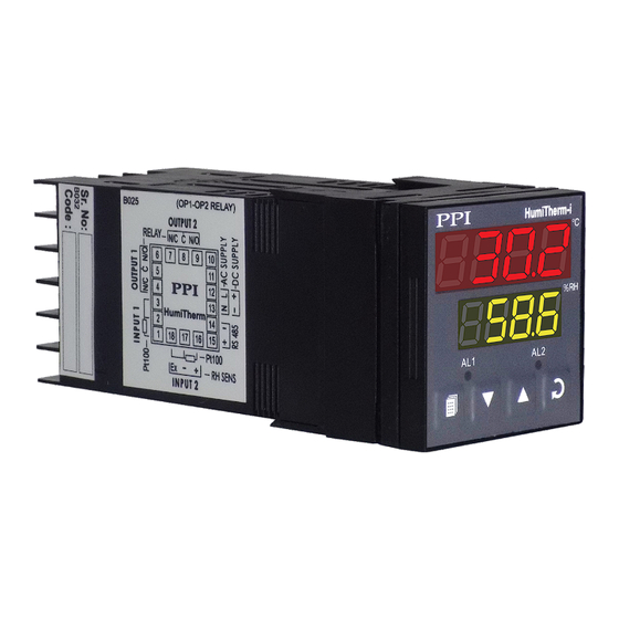
- Page 1 HumiTherm-i Smart ‘Temperature + Humidity’ Indicator Version : Dry-Bulb RTD Pt100, 3-wire Wet-Bulb RTD Pt100, 3-wire Version : RTD Pt100, 3-wire for Temperature DC Linear (Voltage) for Humidity User Manual...
-
Page 2: Table Of Contents
HumiTherm-i User Manual CONTENTS For Dry-Wet FRONT PANEL LAYOUT 2. BASIC OPERATION PAGES AND PARAMETERS ALARM PARAMETERS FOR TEMPERATURE ALARM PARAMETERS FOR RELATIVE HUMIDITY ZERO OFFSET PARAMETERS UTILITY PARAMETERS HARDWARE ASSEMBLY & CONFIGURATIONS MECHANICAL INSTALLATION ELECTRICAL CONNECTIONS For Temp+RH FRONT PANEL LAYOUT 2. - Page 3 HumiTherm-i (Dry-Wet) User Manual Section 1 FRONT PANEL LAYOUT The indicator front panel comprises of digital readouts, LED indicators and membrane keys as shown in Figure 1.1 below. Figure 1.1 HumiTherm-i °C Upper Readout Lower Readout Alarm -1 Indicator Alarm-2 Indicator...
- Page 4 HumiTherm-i (Dry-Wet) User Manual Section 2 BASIC OPERATIONS POWER-UP Upon power-up, all displays and indicators are lit on for approximately 3 seconds. This is followed by the indication of the indicator model name on the Upper Readout and the firmware version on the Lower Readout, for approximately 1 second.
- Page 5 HumiTherm-i (Dry-Wet) User Manual Note: For both Dry and Wet Bulb 3-wire RTD sensor input, if the compensating lead is not connected or gets open, the indicator does not indicate PV error but the measured value is not compensated for the lead resistance.
-
Page 6: Parameter Description
HumiTherm-i (Dry-Wet) User Manual Settings Parameter Description (Default Value) RESET COMMAND Available only if Min./Max. monitoring is enabled. This feature clears the current Min. / Max. values and starts afresh monitoring (Default : No) the Process Values for new Min & Max. - Page 7 HumiTherm-i (Dry-Wet) User Manual Section 3 SET-UP MODE : ACCESS AND OPERATION The various parameters are arranged in different groups, called PAGES, depending upon the functions they represent. Each group is assigned a unique numeric value, called PAGE NUMBER, for its access.
- Page 8 HumiTherm-i (Dry-Wet) User Manual MASTER LOCKING The indicator facilitates locking all the PAGES (except Operator PAGE) by applying Master Lock Code. Under Locking, the parameters are available for view only and cannot be adjusted. The Master Lock, however does not lock the operator parameters.
-
Page 9: Alarm Parameters For Temperature
HumiTherm-i (Dry-Wet) User Manual Section 4 ALARM PARAMETERS FOR TEMPERATURE Visit www.ppiindia.net for technical notes on ALARM for detailed understanding of the parameters / terminologies used for describing the Alarm parameters in this section. The Alarm parameters for Temperature Loop are grouped on PAGE-10. Refer Table 4.1 for parameter description and settings. -
Page 10: Alarm Parameters For Relative Humidity
HumiTherm-i (Dry-Wet) User Manual Section 5 ALARM PARAMETERS FOR RELATIVE HUMIDITY Visit www.ppiindia.net for technical notes on ALARM for detailed understanding of the parameters / terminologies used for describing the Alarm parameters in this section. The Alarm Parameters for %RH Loop are grouped on PAGE-11. Refer Table 5.1 for parameters description and settings. -
Page 11: Zero Offset Parameters
HumiTherm-i (Dry-Wet) User Manual Section 6 ZERO-OFFSET PARAMETERS The Zero-Offset Parameters are grouped on PAGE-12 and allow the user to set the Zero-Offset for Temperature and the Relative Humidity (RH) values. Refer Table 6.1 for parameter description and settings. Table 6.1... - Page 12 HumiTherm-i (Dry-Wet) User Manual Section 7 SUPERVISORY PARAMETERS The Supervisory Parameters are grouped on PAGE-13. These parameters allow Unit Selection for Temperature Value, Enabling / Disabling Min/Max monitoring and settings for Serial Communication. Refer Table 7.1 for parameter description and settings.
-
Page 13: Hardware Assembly & Configurations
HumiTherm-i (Dry-Wet) User Manual Section 8 HARDWARE ASSEMBLY & CONFIGURATIONS The Figure 8.1 below shows the indicator outer-case when viewed with indicator front label upright. The indicator outer case is a rigid plastic enclosure into which the electronics assembly fits. The enclosure in turn fits into the standard DIN size panel cutout, as described in Section 9 : Mechanical Installation. - Page 14 HumiTherm-i (Dry-Wet) User Manual Figure 8.2 ‘UP’ inscribed on topside T P U N / C N / O N / O N / C R E L S S R Bezel S E N ° C P l a...
- Page 15 HumiTherm-i (Dry-Wet) User Manual JUMPER SETTINGS FOR OUTPUT-1 (ALARM-1) The Output-1 is user configurable for Relay or SSR voltage pulses. The selection requires proper jumper-settings prior to electrical connections. Figure 8.4 Pins 1 2 3 4 Link The jumper settings are provided in the form of Pins & Link arrangement on the CPU board towards the rear end. Notice that, there are two such arrangements;...
- Page 16 HumiTherm-i (Dry-Wet) User Manual The double-headed arrows, in Table 8.1, show the positions of the adjoining Pins that require shorting using the Link. The wiring connections must also be made in accordance with the selected output type (NO, C) for Relay; Positive(+) & Negative(-) for SSR.
- Page 17 HumiTherm-i (Dry-Wet) User Manual Figure 8.6 Mounting Output-2 Module H u m i T h e r m - For plugging out the module(s), follow the steps below: 1. Gently pull apart the Power-supply board and the CPU board until the projections of the module board come out of the slots.
-
Page 18: Mechanical Installation
HumiTherm-i (Dry-Wet) User Manual Section 9 MECHANICAL INSTALLATION The Figure 9.1 shows the indicator front outer dimensions and the panel cutout requirements. Figure 9.1 48mm (1.89in) HumiTherm-i °C 45 X 45 mm -0, +0.5 mm (1.77 X 1.77 in) (-0, +0.02 in) -
Page 19: Electrical Connections
HumiTherm-i (Dry-Wet) User Manual Section 10 ELECTRICAL CONNECTIONS WARNING MISHANDLING / NEGLIGENCE CAN RESULT IN PERSONAL DEATH OR SERIOUS INJURY. 1. The user must rigidly observe the Local Electrical Regulations. Do not make any connections to the unused terminals for making a tie-point for other wires (or for any other reasons) as they may have some internal connections. - Page 20 HumiTherm-i (Dry-Wet) User Manual DESCRIPTIONS INPUT-1 : RTD Pt100, 3-Wire (Terminals 1, 2 and 3) Figure 10.2 (a) The indicator accepts 3-wire RTD Pt100 as input for measuring Dry Bulb Temperature Value. Connect single leaded end of RTD bulb to terminal 1 and the double leaded ends to terminal 2 and 3 (interchangeable) as shown in Figure 10.2 (a).
- Page 21 HumiTherm-i (Dry-Wet) User Manual SERIAL COMMUNICATION PORT Connect terminal 15 and 14 of the indicator to (+) and (-) terminals of the Master device for RS485 port. For RS232 port connect terminal 15 to TXD (Transmit), Terminal 14 to RXD (Receive) and Terminal 10 to GND (Ground). To ensure reliable operation of the Serial Communication Link (without data corruption due to line noise or reflections), use a pair of twisted wires inside screened cable with the terminating resistor (100 to 150 Ohms) at one end, as shown in Figure 10.5 below.
- Page 22 HumiTherm-i (Temp+RH) User Manual HumiTherm-i Temp+RH...
-
Page 23: Front Panel Layout
HumiTherm-i (Temp+RH) User Manual Section 1 FRONT PANEL LAYOUT The indicator front panel comprises of digital readouts, LED indicators and membrane keys as shown in Figure 1.1 below. Figure 1.1 HumiTherm-i °C Upper Readout Lower Readout Alarm -1 Indicator Alarm-2 Indicator... - Page 24 HumiTherm-i (Temp+RH) User Manual Table 1.2 Symbol Function Press to enter or exit set-up mode. PAGE Press to decrease the parameter value. Pressing once decreases DOWN the value by one count; keeping pressed speeds up the change. Press to increase the parameter value. Pressing once increases the value by one count;...
-
Page 25: Basic Operation
HumiTherm-i (Temp+RH) User Manual Section 2 BASIC OPERATIONS POWER-UP Upon power-up, all displays and indicators are lit on for approximately 3 seconds. This is followed by the indication of the indicator model name On the Upper Readout and the firmware version on the Lower Readout, for approximately 1 second. - Page 26 HumiTherm-i (Temp+RH) User Manual 2. Press ENTER key. The Lower Readout shows prompt for the first available operator parameter and the Upper Readout shows value for the parameter. 3. Use UP / DOWN keys to adjust the value and then press ENTER key to store the set value and scroll to next parameter.
- Page 27 HumiTherm-i (Temp+RH) User Manual Section 3 SET-UP MODE : ACCESS AND OPERATION The various parameters are arranged in different groups, called PAGES, depending upon the functions they represent. Each group is assigned a unique numeric value, called PAGE NUMBER, for its access.
- Page 28 HumiTherm-i (Temp+RH) User Manual MASTER LOCKING The indicator facilitates locking all the PAGES (except Operator PAGE) by applying Master Lock Code. Under Locking, the parameters are available for view only and cannot be adjusted. The Master Lock, however does not lock the operator parameters.
-
Page 29: Alarm Parameters For Temperature
HumiTherm-i (Temp+RH) User Manual Section 4 ALARM PARAMETERS FOR TEMPERATURE visit www.ppindia.net for technical notes on ALARM for detailed understanding of the parameters / terminologies used for describing the Alarm parameters in this section. The Alarm Parameters for Temperature Loop are grouped on PAGE-10. Refer Table 4.1 for parameter description and settings. -
Page 30: Alarm Parameters For Relative Humidity
HumiTherm-i (Temp+RH) User Manual Section 5 ALARM PARAMETERS FOR RELATIVE HUMIDITY Visit www.ppiindia.net for technical notes on ALARM for detailed understanding of the parameters / terminologies used for describing the Alarm parameters in this section. The Alarm Parameters for %RH Loop are grouped on PAGE-11. Refer Table 5.1 for parameters description and settings. -
Page 31: Zero Offset Parameters
HumiTherm-i (Temp+RH) User Manual Section 6 ZERO-OFFSET PARAMETERS The Zero-Offset Parameters are grouped on PAGE-12 and allow the user to set the Zero-Offset for Temperature and the Relative Humidity (RH) values. Refer Table 6.1 for parameter description and settings. Table 6.1... - Page 32 HumiTherm-i (Temp+RH) User Manual Section 7 SUPERVISORY PARAMETERS The Supervisory Parameters are grouped on PAGE-13. These parameters allow Unit Selection for Temperature Value, Enabling/Disabling Min/Max monitoring and settings for Serial Communication. Refer Table 7.1 for parameter description and settings. Table 7.1...
-
Page 33: Hardware Assembly & Configurations
HumiTherm-i (Temp+RH) User Manual Section 8 HARDWARE ASSEMBLY & CONFIGURATIONS The Figure 8.1 below shows the indicator outer-case when viewed with indicator front label upright. The indicator outer case is a rigid plastic enclosure into which the electronics assembly fits. The enclosure in turn fits into the standard DIN size panel cutout, as described in Section 9 : Mechanical Installation. - Page 34 HumiTherm-i (Temp+RH) User Manual Figure 8.2 ‘UP’ inscribed on topside T P U N / C N / O N / O N / C R E L S S R Bezel S E N ° C P l a...
- Page 35 HumiTherm-i (Temp+RH) User Manual JUMPER SETTINGS FOR OUTPUT-1 (ALARM-1) The Output-1 is user configurable for Relay or SSR voltage pulses. The selection requires proper jumper-settings prior to electrical connections. Figure 8.4 Pins 1 2 3 4 Link The jumper settings are provided in the form of Pins & Link arrangement on the CPU board towards the rear end. Notice that, there are two such arrangements;...
- Page 36 HumiTherm-i (Temp+RH) User Manual The double-headed arrows, in Table 8.1, show the positions of the adjoining Pins that require shorting using the Link. The wiring connections must also be made in accordance with the selected output type (NO, C) for Relay; Positive (+) & Negative (- ) for SSR.
- Page 37 HumiTherm-i (Temp+RH) User Manual Figure 8.6 Mounting Output-2 Module H u m i T h e r m - For plugging out the module(s), follow the steps below: 1. Gently pull apart the Power-supply board and the CPU board until the projections of the module board come out of the slots.
-
Page 38: Mechanical Installation
HumiTherm-i (Temp+RH) User Manual Section 9 MECHANICAL INSTALLATION The Figure 9.1 shows the indicator front outer dimensions and the panel cutout requirements. Figure 9.1 48mm (1.89in) HumiTherm-i °C 45 X 45 mm -0, +0.5 mm (1.77 X 1.77 in) (-0, +0.02 in) -
Page 39: Electrical Connections
HumiTherm-i (Temp+RH) User Manual Section 10 ELECTRICAL CONNECTIONS WARNING MISHANDLING / NEGLIGENCE CAN RESULT IN PERSONAL DEATH OR SERIOUS INJURY. 1. The user must rigidly observe the Local Electrical Regulations. 2. Do not make any connections to the unused terminals for making a tie-point for other wires (or for any other reasons) as they may have some internal connections. -
Page 40: Power Supply
HumiTherm-i (Temp+RH) User Manual DESCRIPTIONS INPUT-1 : RTD Pt100, 3-Wire (Terminals 1, 2 and 3) Figure 10.2 (a) The indicator accepts 3-wire RTD Pt100 as input for measuring Dry Bulb Temperature Value. Connect single leaded end of RTD bulb to terminal 1 and the double leaded ends to terminal 2 and 3 (interchangeable) as shown in Figure 10.2 (a). - Page 41 HumiTherm-i (Temp+RH) User Manual SERIAL COMMUNICATION PORT Connect terminal 15 and 14 of the indicator to (+) and (-) terminals of the Master device for RS485 port. For RS232 port connect terminal 15 to TXD (Transmit), Terminal 14 to RXD (Receive) and Terminal 10 to GND (Ground). To ensure reliable operation of the Serial Communication Link (without data corruption due to line noise or reflections), use a pair of twisted wires inside screened cable with the terminating resistor (100 to 150 Ohms) at one end, as shown in Figure 10.5 below.
- Page 42 Process Precision Instruments 101, Diamond Industrial Estate, Navghar, Vasai Road (E), Dist. Palghar - 401 210.Maharashtra, India 0250 - 2391722/33/37/42 07498799226, 09321985369 sales@ppiindia.net, support@ppiindia.net w w w . p p i i n d i a . n e t...
Need help?
Do you have a question about the HumiTherm-i and is the answer not in the manual?
Questions and answers