
Related Manuals for OEG KMS-D


Summary of Contents for OEG KMS-D
- Page 1 Weather compensated heating controller Witterungsgeführter Heizungsregler Régulateur de chauffage Regolatore climatico Weersafhankelijke warmteregelaar KMS-D, KMS-D+...
- Page 3 Weather compensated heating controller KMS-D, KMS-D+ Witterungsgeführter Heizungsregler KMS-D, KMS-D+ Régulateur de chauffage KMS-D, KMS-D+ Regolatore climatico KMS-D, KMS-D+ Weersafhankelijke warmteregelaar KMS-D, KMS-D+...
-
Page 5: Introduction
Weather compensated controllers KMS-D and KMS-D+ are modern microcontroller based devices, produced in digital SMT technology. KMS-D controllers are intended for control of direct and/or mixing heating circuit or two mixing heating circuits and d. h. w. warming with boiler, solar collectors and other energy sources. -
Page 6: Table Of Contents
CONTENTS Introduction........................5 USER MANUAL Controller description...................... 8 Initial controller setup...................... 9 Graphic LCD display....................... 12 Description and presentation of the basic screen: ..........12 Description of symbols presented on the display ............13 Symbols for heating circuits .................. 13 Symbols for operation mode indication .............. - Page 7 Installation Into the boiler panel cutout...............65 Electric connection of the controller ................66 Connection of temperature sensors ................67 Room unit DD2+......................68 BUS connection to KMS-D, KMS-D+ controllers............69 BUS connection to WHMS controllers................69 Installation and connection of vt safety limiter............70 Controller malfunction......................71 Sensor simulation and controller operation test ............71...
-
Page 8: User Manual
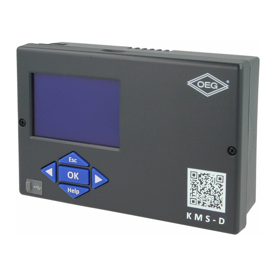
USER MANUAL CONTROLLER DESCRIPTION 1 - Graphic display. button (Esc - return to previous). button (one step back, decrease). 4 - USB connector for connecting personal computer. button (enters a menu, confirms selection). button (Help). button (one step forward, increase). User manual... -
Page 9: Initial Controller Setup
INITIAL CONTROLLER SETUP KMS-D and KMS-D+ heating controllers are equipped with an innovative solution “Easy start” which enables the setup of controller in just three or four easy steps. When the controller is connected to the power supply for the first time, the display first shows the program version and company logo and then the first step of the procedure for controller settings is started. - Page 10 STEP 2 - HYDRAULIC SCHEME SETUP Select a hydraulic scheme for controller operation. Move between schemes with buttons Confirm the selected scheme by pressing All schemes with mixing heating circuit are available for radiators and floor/ wall heating. The controller requires a confirmation of language selection with the button.
- Page 11 STEP 4 - SETUP OF THE HEATING CURVE STEEPNESS FOR THE SECOND CIRCUIT Set the heating curve steepness for the second heat- ing circuit. Change the value with buttons Confirm the selected value by pressing The controller requires a confirmation of the set heat- ing curve steepness with the button.
-
Page 12: Graphic Lcd Display
GRAPHIC LCD DISPLAY On the LCD display we can look up all the important data for the controller operation. DESCRIPTION AND PRESENTATION OF THE BASIC SCREEN: State of the controller's outputs. Time and date. Messages Measured temperatures. warnings. T1=20 T5=45 T7=--- °C T2=-5 T4=45... -
Page 13: Description Of Symbols Presented On The Display
DESCRIPTION OF SYMBOLS PRESENTED ON THE DISPLAY SYMBOLS FOR HEATING CIRCUITS Symbol Description The first (mixing) heating circuit. The second (direct or mixing) heating circuit. D. h. w. warming. SYMBOLS FOR OPERATION MODE INDICATION Symbol Description Room heating. Room cooling. Operation according to program timer - day temperature. -
Page 14: Symbols For Indication Of Temperatures And Other Data
Symbol Description Automatic switchover to summer heating mode. Floor drying. Operation with constant stand-pipe temperature. Remote activation. Boost heating. SYMBOLS FOR INDICATION OF TEMPERATURES AND OTHER DATA Symbol Description Measured temperature. Calculated or requested temperature. Room temperature.* Outdoor temperature. Liquid fuel boiler temperature. Solid fuel boiler temperature. - Page 15 Symbol Description Boiler return-pipe temperature. Flue gases temperature. Temperature of the area where heat pump is installed. D. h. w. circulation pipe temperature. Solar collectors temperature - programmable differential thermostat. Solid fuel boiler temperature - programmable differential thermostat. Heat accumulator temperature - programmable differential thermostat. D.
-
Page 16: Symbols For Protection Functions
Symbol Description Output operation according to program timer. T1, T2, T3,...T8 Temperature measured by sensors T1, T2, T3, T4, T5, T6, T7 or T8. TR1, TR2 Temperature measured by a room sensor or room unit DD2+. Outdoor temperature, obtained through the bus connection. Heat source temperature, obtained through the bus connection. -
Page 17: Symbols For Messages And Warnings
SYMBOLS FOR MESSAGES AND WARNINGS Symbol Description Message In the event of exceeding the maximum temperature or when a pro- tection function is switched on, the symbol on display flashes. When maximum temperature is no longer exceeded or when a protection function has switched off, a turned on symbol will note the recent event. -
Page 18: Entering And Navigating Through The Menu
ENTERING AND NAVIGATING THROUGH THE MENU To enter the menu press the button. , and confirm your selection by press- To navigate through the menu, use buttons ing the button. You can return to the previous screen by pressing If no button is pressed for some time, the screen illumination will be switched off or reduced according to the setting. - Page 19 ECO operation mode. Holiday operation mode. Function switch-off. USER FUNCTIONS FOR THE SECOND HEATING CIRCUIT * PARTY operation mode. ECO operation mode. Holiday operation mode. Function switch-off. USER FUNCTIONS FOR D. H. W. One-time switch-on of d. h. w. warming. Function switch-off.
- Page 20 OPERATION MODE FOR THE SECOND HEATING CIRCUIT* Operation mode according to selected time program. Requested room temperature is set on the controller or room unit, if connected. Operation mode according to day temperature. Requested room temperature is set on the controller. Operation mode according to night temperature.
- Page 21 BASIC SETTINGS User language. Time and date. DISPLAY SETTINGS Duration of active display illumination and return to the main menu. Intensity of active display illumination. Intensity of stand-by display illumination. Contrast. DATA OVERVIEW Graphic display of daily temperatures for the period of past week. Detailed graphic display of temperatures for the current day.
- Page 22 SERVICE PARAMETERS General service parameters. Service parameters for the first heating circuit. Service parameters for the second heating circuit. Service parameters for d. h. w. Service parameters for boilers. Service parameters for alternative energy sources. FUNCTION PARAMETERS Parameters for floor drying. FACTORY SETTINGS Reset of controller parameters.
-
Page 23: Temperature Settings
TEMPERATURE SETTINGS The menu displays the temperatures available by selected hydraulic scheme. Select the temperature with buttons . A new screen with temperatures will open. Selected Current value of requested temperature. temperature (numerical display). Last confirmed value of setting. Graphic display Factory value. -
Page 24: User Functions
USER FUNCTIONS User functions enable additional comfort and benefits of using the controller. The following user functions are available in the menu: First heating circuit Second heating circuit* Domestic hot water Energy sources ** ser fUnctions for the first and second heating circUit PARTY operation mode PARTY function activates operation according to the requested comfort temperature. - Page 25 Holiday operation mode HOLIDAY function activates operation according to the requested saving temperature up to selected date. Select Holiday function with buttons , and activate it with the button. To set the expiration date and requested temperature, select the icon again. Now use the buttons to select the setting you wish to change and press the button.
-
Page 26: Operation Mode Selection
OPERATION MODE SELECTION In the menu are selection of operation mode for each heating circuit, for d. h. w. warming and other operation modes. Following operation modes are available in the menu. First heating circuit Second heating circuit * Domestic hot water Manual operation Switchover between heating and cooling Emissions analysis... - Page 27 anUal operation mode This operation mode is used when testing the heating system or in the event of a malfunc- tion. Each control output can be manually switched on, off or set to operate automatically. Move between individual outputs R1 to R8 with buttons .
-
Page 28: Time Program Settings
TIME PROGRAM SETTINGS Weekly time programs enable automatic switchover between day and night temperature or activation and deactivation of domestic hot water warming. First heating circuit Second heating circuit Domestic hot water For each heating circuit there are two time programs available: First time program Second time program Modifying the time program... - Page 29 Time program editing A new screen appears with the display of time program and three icons for editing the program: - free movement of the cursor - drawing of switch-off interval or night temperature - drawing of switch-on interval or day temperature and confirm the selection by Select the requested command icon with buttons pressing the...
-
Page 30: Basic Settings
BASIC SETTINGS This menu is intended for the setting of language, time, date and display. User language and confirm it by pressing the Select the requested user language with buttons button. Exit the setting by pressing the button. Time and date The exact time and date is set in the following manner: Move through individual data with buttons With the... - Page 31 Display settings The following settings are available: Duration of active display illumination and return to the main menu. Intensity of active display illumination. Intensity of standby display illumination. Contrast. Select and confirm the requested setting with buttons Graphic symbol. Current setting value (numeric).
-
Page 32: Data Overview
DATA OVERVIEW The following icons for accessing data on the controller operations are available in the menu: GRAPHIC DISPLAY OF DAILY TEMPERATURES FOR THE PERIOD OF PAST WEEK Graphic display of daily temperature course for each sensor. Temperatures are recorded for the past week of operation. -
Page 33: Service Settings Manual
SERVICE SETTINGS MANUAL CONTROLLER PARAMETERS All additional settings and adaptations of the controller’s operations are performed with the help of parameters. Available are user, service and function parameters. Located are on the second menu screen. In each group, only the parameters used in the selected hydraulic scheme can be seen. - Page 34 General settings: Para- Parameter name Parameter description Setting range Default meter setting P1.1 AUT. SWITCHOVER Automatic switch-off and switch-on of heating in 0- NO SUMMER / WINTER respect to average one-day outdoor temperature. 1- YES P1.2 AVERAGE OUTDOOR Setting of average one-day outdoor temperature at 10 ÷...
- Page 35 Settings for the second heating circuit: Para- Parameter name Parameter description Setting range Default meter setting P3.1 HEAT CURVE STEEP- Heating curve steepness indicates what temperature 0,2 ÷ 2,2 0,7- floor NESS is required for the heating bodies by a determined 1,0- radia- outdoor temperature.
- Page 36 Para- Parameter name Parameter description Setting range Default meter setting P4.9 STAND-BY TIME FOR Setting of stand-by time for d. h. w. circulation pump. 1 ÷ 60 min D. H. W. CIRCULATION Pump stand-by period is always followed by the pump PUMP running period.
-
Page 37: Heating Curve
HEATING CURVE With adjustion of heating curve the controller is adapted to the building. Proper heating curve adjustion is very important for optimal heating control. Heating curve steepness indicates, what temperature is required for the heating bodies by a determined outdoor temperature. - Page 38 Heat curve diagram Tv (°C) S=2,2 Tvmax S=2,0 S=1,8 S=1,6 S=1,4 S=1,2 S=1,0 S=0,8 Tkmin S=0,6 S=0,4 S=0,2 Tvmin Ta (°C) Outdoor temperature Service setting manual...
-
Page 39: Service Parameters
SERVICE PARAMETERS Service parameters are divided into the following groups: S1 - general settings, S2 - set- tings for the first heating circuit, S3 - settings for the second heating circuit, S4 - settings for domestic hot water, S5 - settings for boilers in S6 - settings for alternative energy sources. - Page 40 General service settings: Para- Parameter name Parameter description Setting Default meter range setting S1.1 HYDRAULIC SCHEME Selection of hydraulic scheme. depends on type of controller S1.2 CODE FOR UNLOCKING This setting enables the change of code which is necessary 0000 - 9999 THE SERVICE SETTINGS to unlock the service settings (S and F parameters).
- Page 41 Para- Parameter name Parameter description Setting Default meter range setting S1.5 T8 SENSOR FUNCTION Selection of function for sensor connected to input T8. 1- RF2 1- RF2, room sensor in circuit 2 2- EF2 2- EF2, sensor for limitation of max. floor temperature in 3- RLF2 circuit 2.
- Page 42 Para- Parameter name Parameter description Setting Default meter range setting S1.6 DIGITAL INPUT T1 AND This setting defines controller operation mode if short circuit 1- REMOTE is detected on input T1 or T6. ACTIV. 1- Day temperature operation mode, regardless to currently 2- DIR.
- Page 43 Service settings for the first heating circuit: Param- Parameter name Parameter description Setting Default eter range setting S2.1 INFLUENCE OF ROOM Set the influence of room temperature deviation. Lower value 0,0 ÷ 3,0 TEMP. DEVIATION means lower influence, higher value means higher influence. S2.2 INFLUENCE OF ROOM Setting of room sensor T1 or T8 influence on the operation of...
- Page 44 Param- Parameter name Parameter description Setting Default eter range setting S2.11 MAX. FLOOR TEMPERA- Setting of maximum floor temperature limitation by floor 10 ÷ 50 °C TURE heating. Setting is active only if floor sensor is installed and parameter S1.4=2 (for sensor T1) or S1.5=5 (for sensor T8). S2.12 MINIMUM STAND-PIPE Setting of minimum stand-pipe temperature in cooling mode.
- Page 45 Param- Parameter name Parameter description Setting Default eter range setting S3.4 PUMP OPERATION Setting of pump operation mode. Settings have the follow- 1- STAND- MODE ing meaning: 2- SWITCH- 1- STAND. (circulation pump of mixing circuit - regular) 2- pump switches off, if requested room temperature is 3- PROG.
- Page 46 Service settings for domestic hot water: Param- Parameter name Parameter description Setting Default eter range setting S4.1 OUTPUT R5 FUNCTION Setting of output R5 alternative operation mode. 1- SCHEME 1- operation according to selected hydraulic scheme 2- EL. 2- d. h. w. warming with electric heater HEATER 3- operation according to selected program timer for d.
- Page 47 Param- Parameter name Parameter description Setting Default eter range setting S4.9 FUNCTION OF CIRCULA- Setting of alternative operation mode for d. h. w. circulation 1- D. H. W. TION OUTPUT output. CIRC. 1- output is used for d. h. w. circulation 2- EL.
- Page 48 Param- Parameter name Parameter description Setting Default eter range setting S5.6 BOILER STAND-BY AT Setting of boiler stand-by at min. boiler temperature. 0- ON MIN. TEMPERATURE This setting has affect only if heating operation mode is 1- DAY TEMP. active. PERIOD 2- OFF S5.7...
- Page 49 Service settings for alternative energy sources: Param- Parameter name Parameter description Setting range Default eter setting S6.1 PROTECTION OF MAX. With this setting is activated protection of max. solar col- 0- NO COLLECTORS OR SOLID lector or solid fuel boiler temperature. If solar collector or 1- YES FUEL BOILER TEMPERA- solid fuel boiler temprature is exceeded, circulation pump...
-
Page 50: Parameters For Floor Drying
Param- Parameter name Parameter description Setting range Default eter setting S6.13 LOCATION OF COLD Cold sensor (T8) place of mount, if it is being used for 1- D. H. W. SENSOR FOR DIFF. differential thermostat. In exact we define storage device TANK THERMOSTAT which is being warmed with solar collectors or solid fuel... -
Page 51: Default Settings
Floor drying profile - default setting: F1.2 F1.5 F1.8 F1.11 °C Days DEFAULT SETTINGS The menu contains the tools to help you set the controller. RESET OF CONTROLLER PARAMETERS Resets all parameter settings P1, P2, P3, P4, P5, P6, S1 (except S1.1), S2, S3, S4, S5, S6 and F to factory set values. -
Page 52: Mixing Heating Circuit
BASIC OPERATION DESCRIPTIONS MIXING HEATING CIRCUIT Stand-pipe temperature calculation The upper limit of stand-pipe temperature calculation is set with maximum stand-pipe temperature - parameters S2.6 and S3.6, lower limit is set with minimum stand-pipe tem- perature - parameters S2.5 and S3.5. Parameters S2.1 and S3.1 are used to set the influ- ence of room temperature deviation on the calculation of stand-pipe temperature, and with the parameters P2.2 and P3.2 you can adjust the parallel shift of heating curve. -
Page 53: Direct Heating Circuit
DIRECT HEATING CIRCUIT Required supply temperature for the direct heating circuit is provided directly by controlling the boiler temperature. Heating switch off If the calculated stand-pipe temperature isn‘t for few °C higher than the room temperature, the heating is automatically switched off. Heating is automatically switched off if room temperature is not measured and when outdoor temperature approaches the required temperature. -
Page 54: Solid Fuel Boiler
Liquid fuel boiler protection If liquid boiler temperature drops below the minimum boiler temperature - parameter P5.1, the mixing valve will gradually begin to close. In case if liquid boiler temperature exceeds the maximum boiler temperature - parameter S5.1, boiler protection is activated. At this point, the maximum boiler temperature - parameters S2.6 and S3.6 is set for the calculated stand-pipe temperature. -
Page 55: Heat Pump
HEAT PUMP Control of heat pump by schemes 122, 122b, 122c and 122d The heat pump (HP) has 2 operation modes, depending on parameter S6.14 setting: - S6.14 = 1 - HP is activated whenever there is a demand for heating and remains switched on for all the time. - Page 56 D. h. w. warming with solar collectors The basic operation of the solar collectors system is determined by switch-on difference, switch-off difference and minimum temperature of solar collectors - parameters P6.1, P6.2 and P6.3. D. h. w. is warmed up to the requested temperature, set with parameter S4.10. If d.
-
Page 57: Domestic Hot Water Circulation
S1.8. OPERATION OF HEATING SYSTEMS WITH TWO HEAT SOURCES KMS-D and KMS-D+ controllers feature fully automatic operation of heating systems with two heat sources, for example with solid and liquid fuel boiler. Systems can operate with or without a heat accumulator. - Page 58 Operation diagram for hydraulic schemes with two heat sources: temperature delay to start source A time LEGEND: A - liquid fuel boiler (heat source A) B - solid fuel boiler or heat accumulator (heat source B) PT - switchover temperature Switch-over from liquid (A) to solid (B) fuel boiler or to heat accumulator When the heat source B temperature exceeds the switchover temperature PT (point 1), the heat source A is switched off.
-
Page 59: Operation Of Switchover Valve By Systems With Two Heat Sources
OPERATION OF SWITCHOVER VALVE BY SYSTEMS WITH TWO HEAT SOURCES For control of switchower valve use 2-point actuator with spring return or classic 2-point actuator with phase-return function. Dot mark on hydraulic schemes indicates valve gate with open flow when the actuator is in base position. -
Page 60: Setting The Minimum Rpm For Pump R6
Serial connection Recommended (default) setting Optional setting S1.16=0 S1.16=1 R8 = OFF R8 = ON R8 = ON R8 = OFF LEGEND: A - liquid fuel boiler B - solid fuel boiler or heat accumulator - valve gate with open flow when the actuator is in base position SETTING THE MINIMUM RPM FOR PUMP R6 A nominal system flow needs to be defined on behalf of installed collector surface. -
Page 61: Differential Controller
DIFFERENTIAL CONTROLLER The KMS-D controllers feature programmable differential controller. It can be activated by schemes with indication , by setting the parameter S1.4=4 for solar collector or S1.4=5 for solid fuel boiler. Activation of differential controller function is possible if R6, T1 and T8 aren’t used by scheme. - Page 62 APPLICATION OF DIFFERENTIAL CONTROLLER FOR SOLID FUEL BOILER Required parameter settings for application with storage tank: S1.4 = 5 S6.13 = 1 Required parameter settings for application with heat accumulator: S1.4 = 5 S6.13 = 2 26 N Differential controller can be activated in schemes 108, 108b, 109, 109b, 111, 113, 116, 116b, 116c, 117, 118, 119, 120, 121, 122, 122b, 122c, 122d, 123e, 123f and 123h.
-
Page 63: Operation Modes In Cases Of Sensor Malfunction
OPERATION MODES IN CASES OF SENSOR MALFUNCTION Outdoor sensor is not connected or has a failure In such case, the controller operates as a P-controller according to room temperature de- viation. If room temperature sensor also has a failure or is not connected, the controller will maintain constant stand-pipe temperature, which is: - 25 °C higher as the set day or night temperature;... -
Page 64: Installation Manual
INSTALLATION MANUAL CONTROLLER INSTALLATION Install controller in dry indoor area away from strong electromagnetic fields. The controller is foreseen for wall installation or boiler panel installation with standard cutout of 138 x 92 mm. WALL INSTALLATION The installation onto a wall is carried out in the following way: 1. -
Page 65: Installation Into The Boiler Panel Cutout
INSTALLATION INTO THE BOILER PANEL CUTOUT The installation into a boiler panel cutout is carried out in the following way: 1. Unscrew both screws (a) from the controller (b) and remove it from the base (c). 2. Remove cable inlet lids (d) and place the cables. Left cable inlet is for sensor cables, right cable inlet is for power supply cables. -
Page 66: Electric Connection Of The Controller
ELECTRIC CONNECTION OF THE CONTROLLER Every heating controller project must be based on calculations and plans that are exclusively your own and pursuant to the regulations in force. Im- ages and texts in these manuals serve as examples and the issuer does not assume any responsibility for them. -
Page 67: Connection Of Temperature Sensors
CONNECTION OF TEMPERATURE SENSORS Immersion sensor Immersion sensor is intended to be installed into immersion tube in boiler, heat accumula- tor, d. h. w. storage tank, solar collectors or elsewhere. Ensure proper contact between sensor and tube. Secure the sensor with a fastener or a screw. Surface sensor Install the surface sensor onto the stand-pipe above the bypass pump or after the mixing valve. -
Page 68: Room Unit Dd2
The KMS-D controllers enable connection of DD2+ room unit which measures room temperature and enables the setting of requested day and night temperature, as well as selection of operation mode. Up to two room units can be connected to a single KMS-D controller. -
Page 69: Bus Connection To Kms-D, Kms-D+ Controllers
GND 12 BUS CONNECTION TO WHMS CONTROLLERS With BUS connection any number of KMS-D or KMS-D+ with WHMS controllers can be connected to network. The first or the master controller physically controls heat sources, while the other (slave) controllers control only the heating circuits. -
Page 70: Installation And Connection Of Vt Safety Limiter
(usually between 40 °C and 60 °C) or the temperature which is at least 5 °C higher as the set maximum allowed stand-pipe temperature on the controller - pa- rameters 2.6 and S3.6. KMS-D, KMS-D+ KMS-D, KMS-D+ +°C +°C... -
Page 71: Controller Malfunction
CONTROLLER MALFUNCTION SENSOR SIMULATION AND CONTROLLER OPERATION TEST The KMS-D and KMS-D+ controllers have a special function installed, which enables simu- lations of all sensors. With the help of this function, user can test controller operation. This function is intended for the cases of start-up, maintenance or testing of the controller. -
Page 72: Technical Data
TECHNICAL DATA Dimensions [w x h x d]: ..........144 x 96 x 49 mm Controller weight ............465 g Body material ............ASA + PC - thermoplastic Supply voltage ............230 V AC, 50 Hz Own consumption ............. 5 VA Cable cross section .......... -
Page 73: Declaration Of Conformity
DECLARATION OF CONFORMITY Heating controllers KMS-D are conformed with the following directives: - LVD: Low Voltage Directive 2006/95/EC, - EMC: Electromagnetic Compatibility Directive 2004/108/EC, - RoHS: Directive on hazardous substances in electrical and electronic equipment, 2002/95/EC. PRODUCT DESCRIPTION: Weather compensated heating controller... -
Page 74: Warranty
30 days if the guarantee is enforced with all the documents and product deliveries done in the headquarters or the nearest authorized OEG workshop. If during the warranty period the product is not corrected within 30 days of notification of failure, the product to the purchaser's request, replaced with a new one. -
Page 75: Hydraulic Schemes
HYDRAULIC SCHEMES / HYDRAULIKSCHEMAS / SCHÉMAS HYDRAULIQUES / SCHEMI IDRAULICI / HYDRAULISCHE SCHEMA‘S IMPORTANT ATTENTION: Installation schemes show operation principles and do not include all auxil- iary and safety elements! Observe the regulations in force when performing installations! WICHTIG ACHTUNG: Die Installationsschemas verweisen auf das Betriebsprinzip und verfügen nicht über alle Hilfs- oder Sicherheitselemente. - Page 76 LEGEND / LEGENDE / LEGENDA / LÉGENDE - possibility of free programming of differential controller - Möglichkeit der Frei-programmierung von Differenzregler - possibilité d’une programmation libre de régulateur différentiel - possibilità del termostato differenziale - mogelijkheid tot vrije programmatie van differentieelregelaar - valve gate with open flow when the actuator is in base position - Markiert den Anschluss der offen in der Ausgangsposition des Umschaltventils ist - raccordement de la vanne de commutation qui est ouvert lorsque le moteur est en position de départ...
- Page 77 101 (KMS-D, KMS-D+) Oil boiler, mixing circuit, d. h. w. storage tank. Flüssigbrennstoffkessel, Mischerheizkreis, Brauchwassererwärmer. Chaudière à fioul, circuit mélangeur, chauffe-eau sanitaire. Caldaia a olio, circuito di miscelato, dispositivo di riscaldamento dell’acqua sanitaria. Olieketel, mengcircuit, warmwatertank. 2 GND 31 32...
- Page 78 101c (KMS-D, KMS-D+) Solid fuel boiler, mixing circuit, d. h. w. storage tank. Festbrennstoffkessel, Mischerheizkreis, Brauchwassererwärmer. Chaudière à fioul, circuit mélangeur, chauffe-eau sanitaire. Caldaia a olio, circuito di miscelato, dispositivo di riscaldamento dell’acqua sanitaria. Boiler voor vaste brandstof, mengcircuit, warmwatertank.
- Page 79 101e (KMS-D, KMS-D+) Extension of the scheme - mixing circuit, d. h. w. storage tank. Erweiterungsschema - Mischerheizkreis, Brauchwassererwärmer. Schéma d’extension - circuit mélangeur, chauffe-eau sanitaire. Sistema di allargamento - circuito di miscelato, dispositivo di riscaldamento dell’acqua sanitaria. Uitbreiding van het schema - mengcircuit, warmwatertank.
- Page 80 103 (KMS-D, KMS-D+) Oil boiler, direct circuit, d. h. w. storage tank. Flüssigbrennstoffkessel, Direktheizkreis, Brauchwassererwärmer. Chaudière à fioul, circuit direct, chauffe-eau sanitaire. Caldaia a olio, circuito diretto, dispositivo di riscaldamento dell’acqua sanitaria. Olieketel, direct circuit, warmwatertank. 2 GND 31 32...
- Page 81 104b (KMS-D, KMS-D+) Heat accumulator, mixing circuit, d. h. w. storage tank, solar collectors. Wärmespeicher, Mischerheizkreis, Brauchwassererwärmer, Solarkollektoren. Ballon d’eau chaude, circuit mélangeur, chauffe-eau sanitaire, capteurs solaires. Serbatoio di calore, circuito di miscelato, dispositivo di riscaldamento dell’acqua sanitaria, collettori solari.
- Page 82 104d (KMS-D, KMS-D+) Heat accumulator with integrated d. h. w. storage tank, mixing circuit, solar collectors. Wärmespeicher mit eingebauten Brauchwassererwärmer, Mischerheizkreis, Solarkollektoren. Ballon d’eau chaude avec chauffe-eau sanitaire intégré, circuit mélangeur, capteurs solaires. Serbatoio di calore con dispositivo di riscaldamento incorporato per l’acqua sanitaria, circuito di miscelato, collettori solari.
- Page 83 104f (KMS-D, KMS-D+) Extension of the scheme - mixing circuit, d. h. w. storage tank. Erweiterungsschema - Mischerheizkreis, Brauchwassererwärmer, Solarkollektoren. Schéma d’extension - circuit mélangeur, chauffe-eau sanitaire, capteurs solaires. Sistema di allargamento - circuito di miscelato, dispositivo di riscaldamento dell’acqua sanitaria, collettori solari.
- Page 84 106 (KMS-D, KMS-D+) Oil boiler, direct circuit, d. h. w. storage tank, solar collectors. Flüssigbrennstoffkessel, Direktheizkreis, Brauchwassererwärmer, Solarkollektoren. Chaudière à fioul, circuit direct, chauffe-eau sanitaire, capteurs solaires. Caldaia a olio, circuito diretto, dispositivo di riscaldamento dell’acqua sanitaria, collettori solari. Olieketel, direct circuit, warmwatertank, zonnecollectoren.
- Page 85 107b (KMS-D, KMS-D+) Oil boiler, direct circuit, d. h. w. storage tank, solar collectors. Flüssigbrennstoffkessel, Direktheizkreis, Mischerheizkreis, Brauchwassererwärmer, Solarkollektoren. Chaudière à fioul, circuit direct, circuit mélangeur, chauffe-eau sanitaire, capteurs solaires. Caldaia a olio, circuito diretto, circuito di miscelato, dispositivo di riscaldamento dell’acqua sanitaria, collettori solari.
- Page 86 108b (KMS-D, KMS-D+) Solid fuel boiler, gas boiler, mixing circuit, d. h. w. storage tank. Festbrennstoffkessel, Gaskessel, Mischerheizkreis, Brauchwassererwärmer. Chaudière à combustible solide, chaudière à gaz, circuit mélangeur, chauffe-eau sanitaire. Caldaia a combustibile solido, caldaia a gas, circuito di miscelato, dispositivo di riscaldamento dell’acqua sanitaria.
- Page 87 109b (KMS-D, KMS-D+) Heat accumulator, gas boiler, mixing circuit, d. h. w. storage tank. Wärmespeicher, Gaskessel, Mischerheizkreis, Brauchwassererwärmer. Ballon d’eau chaude, chaudière à gaz, circuit mélangeur, chauffe-eau sanitaire. Serbatoio di calore, caldaia a gas, circuito di miscelato, dispositivo di riscaldamento dell’acqua sanitaria.
- Page 88 110b (KMS-D, KMS-D+) Heat accumulator, gas boiler, mixing circuit, d. h. w. storage tank. Wärmespeicher, Gaskessel, Mischerheizkreis, Brauchwassererwärmer. Ballon d’eau chaude, chaudière à gaz, circuit mélangeur, chauffe-eau sanitaire. Serbatoio di calore, caldaia a gas, circuito di miscelato, dispositivo di riscaldamento dell’acqua sanitaria.
- Page 89 111 (KMS-D, KMS-D+) Heat accumulator, oil boiler, mixing circuit, d. h. w. storage tank. Wärmespeicher, Flüssigbrennstoffkessel, Mischerheizkreis, Brauchwassererwärmer. Ballon d’eau chaude, chaudière à fioul, circuit mélangeur, chauffe-eau sanitaire. Serbatoio di calore, caldaia a olio, circuito di miscelato, dispositivo di riscaldamento dell’acqua sanitaria.
- Page 90 113 (KMS-D, KMS-D+) Combination (solid fuel / oil) boiler, mixing circuit, d. h. w. storage tank. Kombikessel (Festbrennstoff/Öl), Mischerheizkreis, Brauchwassererwärmer. Chaudière combinée (combustible solide/fioul), circuit mélangeur, chauffe-eau sanitaire. Caldaia combinata (a combustibile solido/olio), circuito di miscelato, dispositivo di riscaldamento dell’acqua sanitaria.
- Page 91 114b (KMS-D, KMS-D+) Solid fuel boiler, heat accumulator, mixing circuit, d. h. w. storage tank. Festbrennstoffkessel, Wärmespeicher, Mischerheizkreis, Brauchwassererwärmer. Chaudière à combustible solide, ballon d’eau chaude, circuit mélangeur, chauffe-eau sanitaire. Caldaia a combustibile solido, serbatoio di calore, circuito di miscelato, dispositivo di riscaldamento dell’acqua sanitaria.
- Page 92 115b (KMS-D, KMS-D+) Solid fuel boiler, heat accumulator, mixing circuit, d. h. w. storage tank. Festbrennstoffkessel, Wärmespeicher, Mischerheizkreis, Brauchwassererwärmer. Chaudière à combustible solide, ballon d’eau chaude, circuit mélangeur, chauffe-eau sanitaire. Caldaia a combustibile solido, serbatoio di calore, circuito di miscelato, dispositivo di riscaldamento dell’acqua sanitaria.
- Page 93 116 (KMS-D, KMS-D+) Oil boiler, heat accumulator, mixing circuit, d. h. w. storage tank. Flüssigbrennstoffkessel, Wärmespeicher, Mischerheizkreis, Brauchwassererwärmer. Chaudière à fioul, ballon d’eau chaude, circuit mélangeur, chauffe-eau sanitaire. Caldaia a olio, serbatoio di calore, circuito di miscelato, dispositivo di riscaldamento dell’acqua sanitaria.
- Page 94 116c (KMS-D, KMS-D+) Oil boiler, heat accumulator with integrated d. h. w. storage tank, mixing circuit. Flüssigbrennstoffkessel, Wärmespeicher mit eingebauten Brauchwassererwärmer, Mischerheizkreis. Chaudière à fioul, ballon d’eau chaude avec chauffe-eau sanitaire intégré, circuit mélangeur. Caldaia a olio, serbatoio di calore con dispositivo incorporato per il riscaldamento dell’acqua sanitaria, circuito di miscelato Olieketel, warmteaccumulator met geïntegreerde warmwatertank, mengcircuit.
- Page 95 118 (KMS-D, KMS-D+) Combination (solid fuel / oil) boiler, mixing circuit, d. h. w. storage tank. Kombikessel (Festbrennstoff/Öl), Mischerheizkreis, Brauchwassererwärmer. Chaudière combinée (combustible solide/fioul), circuit mélangeur, chauffe-eau sanitaire. Caldaia combinata (a combustibile solido/olio), circuito di miscelato, dispositivo di riscaldamento dell’acqua sanitaria.
- Page 96 120 (KMS-D, KMS-D+) Heat pump with electric reheating, direct circuit, d. h. w. storage tank. Wärmepumpe, Nachwärmung mit Elektrik, Direktheizkreis, Brauchwassererwärmer. Pompe à chaleur, chauffage électrique d’appoint, circuit direct, chauffe-eau sanitaire. Pompa di calore, riscaldamento elettrico, circuito diretto, dispositivo di riscaldamento dell’acqua sanitaria.
- Page 97 122 (D-KMS, KMS-D+) Heat pump, heat accumulator with integrated d. h. w. storage tank, mixing circuit. Wärmepumpe, Wärmespeicher mit eingebauten Brauchwassererwärmer, Mischerheizkreis. Pompe à chaleur, ballon d’eau chaude avec chauffe-eau sanitaire int., circuit mélangeur. Pompa di calore, serbatoio di calore con dispositivo incorporato per il riscaldamento dell’acqua sanitaria, circuito di miscelato.
- Page 98 122c (D-KMS, KMS-D+) Heat pump, oil boiler, heat accumulator, mixing circuit, d. h. w. storage tank. Wärmepumpe, Flüssigbrennstoffkessel, Wärmespeicher, Mischerheizkreis, Brauchwassererwärmer. Pompe à chaleur, chaudière à fioul, ballon d’eau chaude, circuit mélangeur chauffe-eau sanitaire. Pompa di calore, caldaia a olio, serbatoio di calore, circuito di miscelato, dispositivo di riscaldamento dell’acqua sanitaria.
- Page 99 123 (KMS-D+) Oil boiler, 2x mixing circuit, d. h. w. storage tank. Flüssigbrennstoffkessel, 2x Mischerheizkreis, Brauchwassererwärmer. Chaudière à fioul, 2x circuit mélangeur, chauffe-eau sanitaire. Caldaia a olio, 2x circuito di miscelato, dispositivo di riscaldamento dell’acqua sanitaria. Olieketel, 2x mengcircuit, warmwatertank.
- Page 100 123c (KMS-D+) Gas boiler, heat accumulator with integrated d. h. w. storage tank, 2x mixing circuit. Gaskessel, Wärmespeicher mit eingebauten Brauchwassererwärmer, 2x Mischerheizkreis. Chaudière à gaz, ballon d’eau chaude avec chauffe-eau sanitaire int., 2x circuit mélangeur. Caldaia a gas, serbatoio di calore con dispositivo incorporato per il riscaldamento dell’acqua sanitaria, 2x circuito di miscelato.
- Page 101 123e (KMS-D+) Heat accumulator, 2x mixing circuit, d. h. w. storage tank. Wärmespeicher, 2x Mischerheizkreis, Brauchwassererwärmer. Ballon d’eau chaude, 2x circuit mélangeur, chauffe-eau sanitaire. Serbatoio di calore, 2x circuito di miscelato, dispositivo di riscaldamento dell’acqua sanitaria. Warmteaccumulator, 2x mengcircuit, warmwatertank.
- Page 102 123g (KMS-D+) Free standing (solid fuel / oil) boiler, 2x mixing circuit, d. h. w. storage tank. Kombikessel (Festbrennstoff/Öl), 2x Mischerheizkreis, Brauchwassererwärmer. Chaudière combinée (combustible solide/fioul), 2x circuit mélangeur, chauffe-eau sanitaire. Caldaia combinata (a combustibile solido/olio), 2x circuito di miscelato, dispositivo di riscaldamento dell’acqua sanitaria.
Need help?
Do you have a question about the KMS-D and is the answer not in the manual?
Questions and answers