Advertisement
Quick Links
Thank you for choosing a NIVELCO instrument.
We are sure that you will be satisfied throughout its use.
1. APPLICATION
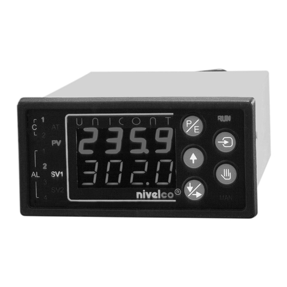
The UNICONT PMM-300 series is a universal display and controller. It can also be used as (one
or two channel) display and limit-switch depending on the configuration of the instrument. For the
complete range of the models, technical data and programming in detail see the INSTALLATION
AND PROGRAMMING MANUAL.
The aim of this User's Manual is to give a concise guideline for applications of the UNICONT
PMM as a process display and limit switch.
2. REAR PANELS
6
7
8 9
U
I
RS485
T
out
14
15
16
17
18
19
20
21
22
AL3
AL4
C
TRD
AC/DC
C1/AL1
C2/AL2
1
5
6
8
2
3
4
7
MAINS
1
2
3
Rear panel for relay output
1
MAINS:
Power supply
2
C1/AL1:
Control or alarm output from relay 1
3
C2/AL2:
Control or alarm output from relay 2
4
I
1:
Analogue current output 1 (proportional to IN1)
out
5
IN1:
Universal input 1
6
AL3-AL4:
Contacts (output) of alarm relay 3 and 4
7
RS485:
Connector for RS485 interface
8
U
:
Transmitter power supply
T
9
I
2:
Analogue current output 2 (proportional to IN2)
out
10
IN2:
Universal input 2
3. WIRING EXAMPLES
2
Use wire of 0,5...2,5 mm
for wiring.
Power supply
11
1
2
CJ1
MAINS
2 A
Cat."B"
~
Relay output 1
3
4
5
RS485 output
0/4-20 mA output
18
19
20
9
+
C
max.600 ohm
Power supply for and signal
from two wire transmitter
21
22
23
11
+
+
CJ1
U
Iout2
T
Transmitter
+
4-20 mA
2
IN2
23
24 25
26
14
15
AL3
AC/DC
9
10
12
13
11
1
2
I
1
CJ1
IN1
out
MAINS
4
5
1
Rear panel for SSR driver output
Voltage input
0/4-20 mA input
12
13
11
12
IN1
CJ1
IN1
+
10 ohm
+
Relay output 2
Relay output 3
14
6
7
8
0/4-20 mA output
10
22
23
+
+
I 1
I 2
out
out
Rt
Rt
max.600 ohm
12
13
21
+
IN1
+
U
10 ohm
6
7
8 9
U
I
2
RS485
IN2
out
T
16
17
18
19
20
21
22
23
24 25
26
AL4
C
TRD
C1/AL1
C2/AL2
3
5
6
9
13
4
7
8
10
11
12
I
1
CJ1
IN1
out
SSR
SSR
2
3
4
5
0/4-20 mA input
13
24
25
26
IN2
10 ohm
+
Relay output 4
15
16
17
SSR1 driver output
SSR2 driver output
3
4
6
7
+
+
Power supply for and signal
from three wire transmitter
22
23
11
12
13
+
CJ1
IN1
+
Iout2
T
Transmitter
+
+
10 ohm
0/4-20 mA
U U U S S S E E E R R R ' ' ' S S S M M M A A A N N N U U U A A A L L L
for applications as display and limit switch
valid from software version (indicated at S.PrG)
202 and higher
4. ACCESSORIES
1
Installation and Programming Manual
1
User's Manual
2
Mounting brackets
1
KTY83 for cold junction compensation
1
Resistor for shunting the input
with models configured for current input
10 Ohm MR-25, 1%, 0,25W
(2 pcs with models with 2 inputs)
1 set
Plug-in terminal box
1 set
Measurement stickers
5. PUTTING INTO OPERATION
The Steps of putting into operation are:
- wiring
- switching on the instrument
- setting
Factory
Default
The PMM is delivered with (temperature
control oriented) Factory Default A. Therefore
you have to change over to Factory Default B
(See Triple Push-Button Operation)
- changing parameters and Electronic Dip
Switch (EDS) position (if necessary)
Programming will be carried out by the push-
buttons on the front panel (see Point 6.)
The
programming
flow
Menu/Submenu points are shown in Point 7.
The Submenu points with grey background are
not used in applications as indicator and limit-
switch.
- With instruments with one input only, the
lower (green) row will not be used as display
but only for entering the values to be
programmed.
(if
necessary)
chart
and
the
Advertisement

Summary of Contents for NIVELCO UNICONT PMM-300
-
Page 1: Rear Panels
We are sure that you will be satisfied throughout its use. 1. APPLICATION The UNICONT PMM-300 series is a universal display and controller. It can also be used as (one or two channel) display and limit-switch depending on the configuration of the instrument. For the complete range of the models, technical data and programming in detail see the INSTALLATION AND PROGRAMMING MANUAL. - Page 2 Indicators LED status 6. FRONT PANEL AL1: “ON”: Relay 1. (programmed) is energised AL2: “ON”: Relay 2. (programmed) is energised AL3: “ON”: Relay 3. (programmed) is energised AL4: “ON”: Relay 4. (programmed) is energised SV2: “ON”: Second input (IN2) is displayed in green (lower row) ...
- Page 3 C.in.1 Factory Default xxx01110 “A” – Process control oriented 9. UNICONT PMM-300 AS TWO-CHANNEL DISPLAY xxx11010 “B” – Process indicator with limit switch (4-20 mA input) AND LIMIT-SWITCH Note: “X” means that the position of EDS is irrelevant concerning Factory Default.
-
Page 4: Error Messages
AL4 hysteresis is lower asymmetrical configuration. (Filling control) 01000000 AL4 hysteresis is upper asymmetrical (Emptying control) 10000000 AL4 hysteresis is symmetrical NIVELCO Process Control Ltd. PM30G0A2 Note: 05.05.2000 The hysteresis of the relays AL5 and AL6 is always symmetric. Set hysteresis at S.A*h.