Table of Contents
Advertisement
Quick Links
Advertisement
Table of Contents

Subscribe to Our Youtube Channel
Related Manuals for Cognex IN-SIGHT

Summary of Contents for Cognex IN-SIGHT
- Page 1 I I I I S S S S S S S S L L L L A A A A I I I I R R R R - - - - & & & & ™ ™ ™ ™ N N N N IGHT IGHT...
-
Page 2: Copyrights And Trademarks
Copyrights and Trademarks The information in this document is subject to change without notice and should not be construed as a commitment by Cognex Corporation. Cognex Corporation is not responsible for any errors that may be present in this document. - Page 3 1 Introduction The In-Sight™ Strobe Light Adapter (Cognex P/N CLA-2000-00) is designed for use with an In-Sight 2000 or 3000 system and most Cognex Light Modules (CLMs), including the Ring Light (P/N CLM-4236), the Dome Light (P/N CLM-7248), and the Spot Light (CLM-2420).
- Page 4 In-Sight Strobe Light Adapter Installation & Reference...
-
Page 5: Installation
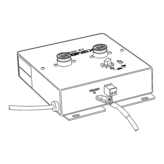
2 Installation This section describes how to connect the Strobe Light Adapter to the In-Sight 2000 or 3000 processor and the Cognex Light Module. STEP 1 – Connect the Cables 1. Remove power from the In-Sight processor. 2. Plug the 8-pin male mini-DIN connector of the Strobe Adapter power cable into the port labeled LIGHTS on the In-Sight processor (Figure 2-1). - Page 6 A two-pin terminal plug may already be attached to the Strobe Control cable. To use the trigger input on the In-Sight camera you must remove this terminal plug and follow the remaining instructions in this step. To use the camera without the built-in triggering input, leave the two-pin plug attached to the Strobe Control cable, then insert the plug into pins 3 and 4 of the receptacle on the back of the camera.
- Page 7 In-Sight Strobe Light Adapter Installation & Reference 6. Push the 7-pin DIN male connector from the Cognex Light Module onto either of the two available 7-pin DIN light module jacks. Rotate the collar on the connector to lock it in place.
- Page 8 The light pulse width is set by adjusting both controls until a suitable light intensity level can be achieved within the In-Sight camera’s exposure time. The effect of the switches is additive, so any light pulse width between 10 microseconds and 290 microseconds can be set.
- Page 9 Connect your trigger circuit to pins 1 (Trigger+) and 2 (Trigger-) on the terminal block on the back of the In-Sight camera (Figure 2-3). Remember to set the Trigger parameter within the AcquireImage function’s property sheet (located in cell A0) to Camera (Figure 2-6).
- Page 10 In-Sight Strobe Light Adapter Installation & Reference • Trigger via the Discrete I/O Connect your trigger circuit to IN+ and IN- terminals on the In-Sight processor (Discrete I/O Lines 8 and 9 are on the processor) using the terminal block. Remember to set the Discrete Input Type to Acquisition Trigger from the Discrete Input dialog (Figure 2-7).
- Page 11 The In-Sight System can be software triggered in one of two ways: • Manual Trigger the In-Sight Camera manually by pressing the Trigger button on the Control Pad or F5 from the keyboard. Remember to set the Trigger Parameter within the AcquireImage function’s property sheet to Manual.
- Page 12 In-Sight Strobe Light Adapter Installation & Reference...
-
Page 13: Troubleshooting
• Verify the Strobe Control Cable is connected to the correct outputs (pins 3 and 4) on the In-Sight Camera. • Verify the Cognex Light Module works by itself when connected directly to the LIGHTS port on the In-Sight processor. - Page 14 In-Sight Strobe Light Adapter Installation & Reference...
-
Page 15: General Specifications
4 Specifications The specifications of the In-Sight Strobe Light Adapter are presented in the following two sections. Summary of Specifications Mechanical Specifications 4.1 General Specifications FEATURE DESCRIPTION Part Number CLA-1000-00 Light Output Jacks Two 7-pin DIN output jacks compatible with Cognex light modules. -
Page 16: Mechanical Specifications
In-Sight Strobe Light Adapter Installation & Reference 4.2 Mechanical Specifications Figure 4-1: In-Sight Strobe Adapter Mechanical Specification... - Page 17 In-Sight Strobe Light Adapter Installation & Reference...
- Page 18 P/N 597-0005-02...
Need help?
Do you have a question about the IN-SIGHT and is the answer not in the manual?
Questions and answers