Table of Contents
Advertisement
Quick Links
Style 6032
UNIVERSAL II CONTROL
INSTALLATION, OPERATION & MAINTENANCE MANUAL
WARRANTY
WARRANTY AND DISCLAIMER: We warrant Akron Brass products for a period of five (5) years* after purchase against defects in ma-
terials or workmanship. Akron Brass will repair or replace product which fails to satisfy this warranty. Repair or replacement shall be
at the discretion of Akron Brass. Products must be promptly returned to Akron Brass for warranty service. We will not be responsible
for: wear and tear; any improper installation, use, maintenance or storage; negligence of the owner or user; repair or modification
after delivery; failure to follow our instructions or recommendations; or anything else beyond our control. WE MAKE NO WARRAN-
TIES, EXPRESS OR IMPLIED, OTHER THAN THOSE INCLUDED IN THIS WARRANTY STATEMENT, AND WE DISCLAIM ANY IMPLIED
WARRANTY OF MERCHANTABILITY OR FITNESS FOR ANY PARTICULAR PURPOSE. Further, we will not be responsible for any conse-
quential, incidental or indirect damages (including, but not limited to, any loss of profits) from any cause whatsoever. No person has
authority to change this warranty.
*Unless otherwise provided herein. Akron Brass industrial electronic components & the Severe-Duty Monitor have a one (1) year war-
ranty. Weldon products have a one (1) year warranty (excluding consumable components). Select Weldon LED products carry a five
(5) year warranty. For Weldon product returns call 800-989-2718. Yamaha and Honda products have the manufacturers' warranty and
Akron Brass disclaims any warranty in respect of those products.
122552
Advertisement
Table of Contents

Subscribe to Our Youtube Channel
Related Manuals for Akron 6032

Summary of Contents for Akron 6032
- Page 1 Akron Brass will repair or replace product which fails to satisfy this warranty. Repair or replacement shall be at the discretion of Akron Brass. Products must be promptly returned to Akron Brass for warranty service. We will not be responsible for: wear and tear;...
-
Page 2: Table Of Contents
TABLE OF CONTENTS 0. SAFETY SUMMARY ............4. - Page 3 LIST OF ILLUSTRATIONS Figure 1-1 Universal II Control Box ..........Figure 2-1 Universal II Mounting Hole Locations .
-
Page 4: Safety Summary
SAFETY SUMMARY SIGNAL WORD DEFINITION Per the ANSI Z535.4 standard, the following signal words and definitions are used to indicate hazardous situations: DANGER indicates an imminently hazardous situation that, if not avoided, will result in death or serious injury. WARNING indicates a potentially hazardous situation that, if not avoided, could result in death or serious injury. CAUTION indicates a potentially hazardous situation that, if not avoided, may result in minor or moderate injury. - Page 5 Safety Instruction – Operation! All operators must read the Operation section of this manual and be properly trained. Safety Instruction – Operation! Use only appropriate Akron Brass Company nozzles. Use of any other nozzles could affect the speed or operation of the monitor/turret.
-
Page 6: Introduction
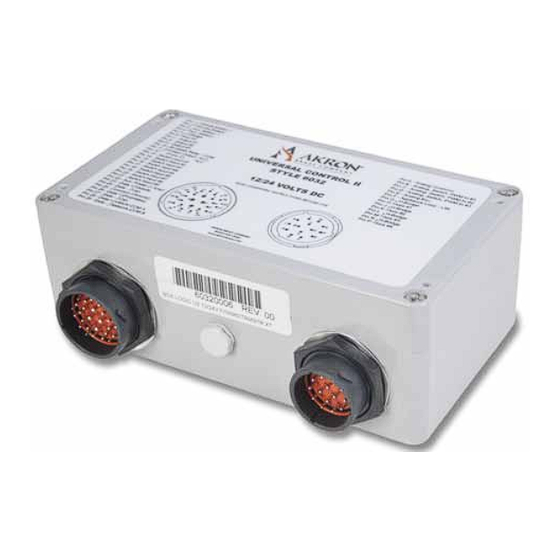
1.3 DESCRIPTION The Universal II is a product used to control Akron Brass monitors and turrets. The unit is designed for installation on any vehicle for the purpose of providing control of Akron Brass electrically operated monitors or turrets. Refer to Figure 1-1 for identification of the Universal II Control Box. -
Page 7: Technical Information
For long runs, it may be necessary to add an intermediate junction box fed by 10 AWG or heavier wiring with a short 12 AWG run applied to the Universal II. If you need assistance in assessing wiring needs associated with long wir- ing runs, contact Akron Brass technical support. INPUT POWER REQUIREMENT: 12VDC (Min: 11VDC;... -
Page 8: Installation
CHAPTER 2 INSTALLATION Safety Instruction -Trained Personnel Only! Only trained and qualified personnel should perform installation, adjustments, and servicing. Only a properly trained and qualified certified electrician should perform electric installations and service. Safety Instruction – Installation! Make the connection of the vehicle and/or auxiliary battery the final step. 2.1 INTRODUCTION The Universal II has been designed to provide ease of installation. -
Page 9: Attaching To Vehicle
2.3 ATTACHING TO VEHICLE 2.3.1 Universal II If the Universal II is to be mounted in a well, be certain that adequate drainage is provided. While the unit has been designed to withstand adverse environmental conditions, it cannot be submerged. The Universal II has two options for mounting: 1. -
Page 10: Cable(S) Installation
Analog Exc. Pin E - Analog Exc. (+5 volts) Appliance Loop (Tied to Gnd if non “Smart Harness”) (LIN Bus) Pin F - Appliance Loop - LIN STYLE 6032 + (Up) H-Bridge Pin G - H-Bridge Elevation Axis #1 - (Close) -
Page 11: Dc Power/Signal Cable
Input #2 tool is available from Ladd Industries part number HDT-48-00 (AKRON #773426). Please refer to Table 2-3 and Figure 2-3 for pin-out information. NOTE: For ease of installation, a connector kit including connector, pins, and sealing plugs (for unused pins) is available... -
Page 12: Generic Dc Power/Signal Connector Pin-Out
2.4.4 Generic DC Power/Signal Connector Pin-out (Example below from part number 60320014 – 3356 Trident Dual Gallonage monitor) 29 Pin Male Mixed AWG Connector – HDP26-24-29SE Pin Number Type Potential Function Comments + Battery Power Input Main Battery (Vehicle) - Battery + Battery Power Input Auxiliary Battery... -
Page 13: Connecting Remote Devices
If one is sensed, it is engaged and a small amount of trickle charge is applied. If this optional feature is not used, it is recommended these pin locations be fitted with Deutsch pin sealing plugs. Contact Akron Brass technical support if you have additional questions about the use of this feature. -
Page 14: Pins 10-12: Relay Contact Output
Switch Inputs #2 to #9 (pins 14 to 21) are primarily intended for toggle switch inputs. Their function varies depending on configuration. An Akron Brass Operator Station can be used or user can provide their own switch inputs. Please refer to the Appendix for the particular version Universal II for their assigned function. -
Page 15: Pins 22 & 25: Peripheral Power Output
AUX. POWER OUT (1 AMP) 16AWG. VEHICLE CAN HI 20AWG. VEHICLE CAN LO 20AWG. BLACK COMMON (GROUND) 16AWG. AKRON BRASS CAN HI 16AWG. AKRON BRASS CAN LO 20AWG. WELDON V-MUX COM A 16AWG. WELDON V-MUX COM B 20AWG. CUSTOMER WIRING USES DEUTSCH #HDP26-24-29SE... -
Page 16: Figure 2-9 J1939 Can Wiring
YELLOW GREEN YELLOW GREEN YELLOW VEHICLE CAN HI GREEN VEHICLE CAN LO COMMON Figure 2-9 J1939 CAN Wiring... -
Page 17: Pins 26 & 27: Not Used
Connection to a VMUX communications bus is available on pins 28 and 29. Pin 28 is VMUX A and Pin 29 is VMUX B. Not all soft- ware versions support VMUX communication. Contact Akron Brass technical support for details of your particular version. If this optional feature is not used, it is recommended these pin locations be fitted with Deutsch pin sealing plugs. -
Page 18: Operating Instructions
The Universal II control system is based on a distributed intelligence control structure. Each device in the system has a circuit board with an embedded micro controller. These devices include (but are not limited to): the 6032 Universal II Control Box, the 6033 Mini Universal, the 6034 CAN Operator Interface, the 6035 CAN Joystick, the 6036 CAN Direction Indicator, the 6037 CAN Wireless Interface, and the associated handheld Remote Control(s). - Page 19 To enter the setup mode for the above functions, follow these steps: 1. Turn power off to Universal II 2. Press and HOLD stream switch (can be done on Joystick or toggle switch box) 3. Turn power on to Universal II while continuing to hold the stream switch 4.
-
Page 20: Soft Limit Positions, Monitor Orientation, And Obstacle Avoidance
While any and all of these configurations are optional, if a monitor/turret orientation is mounted sideways or inverted, the monitor orientation will need to be configured for proper operation. If at any point it is determined that an undesirable mode is active, it is possible to abort the mode by removing power to the Universal II prior to activating the Fog input. -
Page 21: Restore Factory Defaults
3.2.1.6 Position Sensor Zero (Blink Code 1-8) – It is often difficult for the vehicle manufacturer to mount the monitor/turret in the precise position where “straight ahead and level” matches the calibration of the monitor/turret at the Akron Brass factory. Use of this mode allows the user to “re-zero” the sensors at the desired “straight ahead and level” position. First, use the Up/Down Left/Right to position the monitor/turret “straight ahead and level”. -
Page 22: Stow
3.2.1.11 Obstacle Avoidance Learn (Blink Code 2-4) – This function elecation sets The Lower Limits across the horizontal range of the monitor. For instance, a monitor located on the center of a cab roof might need to raise the nozzle slightly to avoid hitting the corners of the cab as it sweeps from side to side. -
Page 23: Deploy
The Universal II has nine switch inputs located on the vehicle connector (see Figure 2 3 and Table 2 3). Below are the various functions that the Universal II switch inputs can provide. Each variant of 6032 will have some combination of these, but not necessarily all or in the order presented here. -
Page 24: Master Monitor/Turret Up/Down Switch
3.3.2 Master Monitor/Turret Up/Down Switch When this switch input functionality is provided, it is best fed by a center-off toggle switch with momentary positions each side of center off. When the common of the switch is connected to +Battery by moving the toggle to the “Up” position, the monitor/turret will be driven upward until the switch is released, a soft-limit is encountered, a hard stop is encountered, or some other disabling function is encountered. -
Page 25: Flow Rate High/Low Switch
3.3.7 Slave Monitor/Turret Left/Right Switch When this switch input functionality is provided, it is best fed by a center-off toggle switch with momentary positions each side of center off. When the common of the switch is connected to +Battery by moving the toggle to the “Right” position, the monitor/tur- ret will be driven to the right until the switch is released, a soft-limit is encountered, a hard stop is encountered, a Master Left/Right switch is activated, or some other disabling function is encountered. -
Page 26: Description Of Logic Output Functions
3.4.1 Panel LED The Panel LED output is normally tied to the LED located in Akron Brass four switch operator stations such as the 60410003. This LED primarily indicates whether or not the monitor/turret is stowed. It also is used to present various codes by associated flash sequences. -
Page 27: Maintenance And Service Instructions
CHAPTER 4 MAINTENANCE AND SERVICE INSTRUCTIONS 4.1 MAINTENANCE INSTRUCTIONS The Universal II has no user-serviceable parts, but steps can be taken to extend its trouble-free operation. • Periodically check cabling for insulation cracking and wire connections for frayed wires. • Insure there is no standing water around the enclosure. •... -
Page 28: Can Messaging
CHAPTER 5 CAN MESSAGING 5.1 CAN ADDRESS CLAIMING 5.1.1 Prerequisite Knowledge It is assumed that the reader has some level of familiarity with CAN networking and terminology, and the AB product. This information is not intended to be a tutorial on CAN, nor AB product operation, but rather a resource for information concerning the requirements and techniques involved in implementing a CAN control interface to the AB product. - Page 29 Input Messages J1939 Basic Joystick Message (PGN 0xFDD6) Header (29 bits) 2 22 11 00 0 8 ... 43..65..87..0 011001111110111010110 [ A ] 3 bits, Priority 3 (011) 2 bits, 00 16 bits, PGN 0xFDD6 [A] = 8 bits, Source (Joystick node address, 0x33 – 0x38) Data length –...
- Page 30 Status Messages – Broadcast Message type 0xFF – Address Announcement This message is issued to inform the integrator what CAN node address has been claimed for use by the AB device having the indi- cated PIN (15 digit unique Product Identification Number). The integrator should save the source node from the message header to use as the destination node in all messages for this device, and to check the source node of an incoming message to determine if it is from this device.
- Page 31 Status Messages – Broadcast (continued) Message type 0x01 – Position / Limit Status This message is issued periodically (100ms) indicating axis positions, travel limit status, et.al. It is used by the 6036xxxx Direction Indicator to obtain rotstion and elevation positions for display. Header (29 bits) 2 8..
- Page 32 Status Messages – Broadcast (continued) Message type 0x81 – Rotation Limits This message is issued periodically (100ms) to allow the 6036xxxx Direction Indicator to display programmed soft limits or oscillation limits. Header (29 bits) 8..43..65..87..0 110001110111111111111 [ A ] 3 bits, Priority 6 (110) 2 bits, 00 8 bits, 0xEF 8 bits, Target (0xFF - Broadcast)
- Page 33 Status Messages – Broadcast (continued) Message type 0x82 – Elevation Limits This message is issued periodically (100ms) to allow the 6036xxxx Direction Indicator to display programmed soft limits. Header (29 bits) 2 22 8..43..65..87..0 110001110111111111111 [ A ] 3 bits, Priority 6 (110) 2 bits, 00...
- Page 34 Status Messages – Broadcast (continued) Message type 0x83 – CAN Outputs This message is issued periodically (100ms) to allow the 6037xxxx Wireless Interface to display status indications. Header (29 bits) 22 11 00 0 8... 43..65..87..0 110001110111111111111 [ A ] 3 bits, Priority 6 (110) 2 bits, 00...
- Page 35 Status Messages – Poll / Response Message type 0x02 – Fault Status Poll Header (29 bits) 8..43..65..87..0 1100011101111 [ A ] [ B ] 3 bits, Priority 6 (110) 2 bits, 00 8 bits, 0xEF = 8 bits, Target (AB node address) = 8 bits, Source (Integrator node address) Data length –...
- Page 36 Status Messages – Poll / Response Message type 0x04 – pCode Version Poll Header (29 bits) 00 0 8..43..65..87..0 1100011101111 [ A ] [ B ] 3 bits, Priority 6 (110) 2 bits, 8 bits, 0xEF = 8 bits, Target (AB node address) = 8 bits,...
- Page 37 Status Messages – Poll / Response (continued) Message type 0x02 – Fault Status Response Header (29 bits) 2 8... 43..65..87..0 1100011101111 [ A ] [ B ] 3 bits, Priority 6 (110) 2 bits, 00 8 bits, 0xEF [A] = 8 bits, Target (Integrator node address)
- Page 38 Status Messages – Poll / Response (continued) Message type 0x03 – Firmware Version Response Header (29 bits) 8...43..65..87..0 1100011101111 [ A ] [ B ] 3 bits, Priority 6 (110) 2 bits, 00 8 bits, 0xEF 8 bits, Target (Integrator node address) 8 bits, Source (AB node address) Data length –...
- Page 39 Status Messages – Poll / Response (continued) Message type 0x04 – pCode Version Response Header (29 bits) 2 22 8... 43..65..87..0 1100011101111[ A ][ B ] 3 bits, Priority 6 (110) 2 bits, 00 8 bits, 0xEF = 8 bits, Target (Integrator node address) bits, Source (AB node address)
- Page 40 Status Messages – Poll / Response (continued) Message type 0x05 – Config Version Response Header (29 bits) 8... 43..65..87..0 1100011101111 [ A ][ B ] 3 bits, Priority 6 (110) 2 bits, 8 bits, 0xEF [A] = 8 bits, Target (Integrator node address) 8 bits, Source (AB node address)
- Page 41 Configuration Messages – Request / Ack Message type 0x41 – Zero Axis Positions Request Header (29 bits) 00 0 8..43..65..87..0 1100011101111 [ A ] [ B ] bits, Priority 6 (110) bits, 00 bits, 0xEF [A] = 8 bits, Target (AB node address) bits, Source (Integrator node address) Data length –...
- Page 42 ASCII Bidirectional Data Pipe Messages (internal / diagnostic use) Message type 0xFE – ASCII Bidirectional Data Pipe Send Header (29 bits) 2 22 00 0 8... 43..65..87..0 1100011101111 [ A ] [ B ] 3 bits, Priority 6 (110) 2 bits, 00 8 bits, 0xEF [A] = 8 bits, Target...
-
Page 43: Appendix A Address Claiming
Appendix A – Address Claiming Address claiming, detailed in ‘SAE J1939-81 Network Management’, is the technique used by AB devices to acquire a node address on the CAN network. It is generally compatible with devices using fixed node addresses, as the fixed node address range is 127 (0x7F) and below, with the dynamic address range 128 (0x80) and above. -
Page 44: Appendix B Joystick Data
Appendix B – Handling of Joystick Input Data Joystick inputs are mapped to 6032xxxx inputs as follows: X axis right – Rotate Right with proportional speed control X axis left – Rotate Left with proportional speed control Y axis back – Elevate Up with proportional speed control Y axis forward –... -
Page 45: Universal Ii Variant Details
CHAPTER 6 UNIVERSAL II VARIANT DETAILS 6.1 60320004 3356 TRIDENT W/ WABASH POSITION SENSORS (OBSOLETE) CONNECTOR – J1 Function Configuration Vehicle Battery + Vehicle Battery + Vehicle Battery - Chassis/Ground/Negative Aux. Battery + (Optional) Positive Aux. Battery - (Optional) Negative H-Bridge –... - Page 46 6.2 60320006 3598 STEAMMASTER XT CONNECTOR – J1 Function Configuration Vehicle Battery + Vehicle Battery + Vehicle Battery - Chassis/Ground/Negative Aux. Battery + (Optional) Positive Aux. Battery - (Optional) Negative H-Bridge – Axis 5 (ON) Discharge moves on when pin 5 positive with respect to pin 6 (OFF) Discharge moves off when pin 6 positive with respect to pin 5 Output #1 Switch Panel LED (Sourcing Out, 2 Amps Max.)
- Page 47 6.3 60320008 3450 ULTRA- HIGH PRESSURE MONITOR CONNECTOR – J1 Function Configuration Vehicle Battery + Vehicle Battery + Vehicle Battery - Chassis/Ground/Negative Aux. Battery + (Optional) Positive Aux. Battery - (Optional) Negative H-Bridge – Axis 5 (On) Discharge moves on when pin 5 positive with respect to pin 6 (Off) Discharge moves off when pin 6 positive with respect to pin 5 Output #1 Switch Panel LED (Sourcing Out, 2 Amps Max.)
- Page 48 6.4 60320010 3356 TRIDENT SINGLE GALLONAGE W/HARNES ID (OTC SPECIAL) CONNECTOR – J1 Function Configuration Vehicle Battery + Vehicle Battery + Vehicle Battery - Chassis/Ground/Negative Aux. Battery + (Optional) Positive Aux. Battery - (Optional) Negative H-Bridge – Axis 5 (On) Discharge moves on when pin 5 positive with respect to pin 6 (Off) Discharge moves off when pin 6 positive with respect to pin 5 Output #1 Discharge Out (Sourcing Out, 2 Amps Max.)
- Page 49 6.5 60320012 3463 FIREFOX W/ POSITION FEEDBACK (POTS) CONNECTOR – J1 Function Configuration Vehicle Battery + Vehicle Battery + Vehicle Battery - Chassis/Ground/Negative Aux. Battery + (Optional) Positive Aux. Battery - (Optional) Negative H-Bridge – Axis 5 (On) Discharge moves on when pin 5 positive with respect to pin 6 (Off) Discharge moves off when pin 6 positive with respect to pin 5 Output #1 Switch Panel LED (Sourcing Out, 2 Amps Max.)
- Page 50 6.6 60320014 3356 TREDENT DUAL GALLONAGE W/ NOVO SENSORS CONNECTOR – J1 Function Configuration Vehicle Battery + Vehicle Battery + Vehicle Battery - Chassis/Ground/Negative Aux. Battery + (Optional) Positive Aux. Battery - (Optional) Negative H-Bridge – Axis 5 (On) Discharge moves on when pin 5 positive with respect to pin 6 (Off) Discharge moves off when pin 6 positive with respect to pin 5 Output #1 Switch Panel LED (Sourcing Out, 2 Amps Max.)
- Page 51 6.7 60320016 3463 FIREFOX W/ MAG SWITCHES CONNECTOR – J1 Function Configuration Vehicle Battery + Vehicle Battery + Vehicle Battery - Chassis/Ground/Negative Aux. Battery + (Optional) Positive Aux. Battery - (Optional) Negative H-Bridge – Axis 5 (On) Discharge moves on when pin 5 positive with respect to pin 6 (Off) Discharge moves off when pin 6 positive with respect to pin 5 Output #1 Switch Panel LED (Sourcing Out, 2 Amps Max.)
- Page 52 6.8 60320018 3353/3354 TUCKAWAY W/ POSITION FEEDBACK (POTS) CONNECTOR – J1 Function Configuration Vehicle Battery + Vehicle Battery + Vehicle Battery - Chassis/Ground/Negative Aux. Battery + (Optional) Positive Aux. Battery - (Optional) Negative H-Bridge – Axis 5 (On) Discharge moves on when pin 5 positive with respect to pin 6 (Off) Discharge moves off when pin 6 positive with respect to pin 5 Output #1 Switch Panel LED (Sourcing Out, 2 Amps Max.)
-
Page 53: Revisions
CHAPTER 7 REVISIONS Revision 0, October 2010: Initial Release. - Page 54 6.8 60320020 3353/3354 TUCKAWAY W/ NOVO SENSORS CONNECTOR – J1 Function Configuration Vehicle Battery + Vehicle Battery + Vehicle Battery - Chassis/Ground/Negative Aux. Battery + (Optional) Positive Aux. Battery - (Optional) Negative H-Bridge – Axis 5 (On) Discharge moves on when pin 5 positive with respect to pin 6 (Off) Discharge moves off when pin 6 positive with respect to pin 5 Output #1 Switch Panel LED (Sourcing Out, 2 Amps Max.)
- Page 55 6.7 60320022 3463 FIREFOX W/ NOVO SENSORS CONNECTOR – J1 Function Configuration Vehicle Battery + Vehicle Battery + Vehicle Battery - Chassis/Ground/Negative Aux. Battery + (Optional) Positive Aux. Battery - (Optional) Negative H-Bridge – Axis 5 (On) Discharge moves on when pin 5 positive with respect to pin 6 (Off) Discharge moves off when pin 6 positive with respect to pin 5 Output #1 Switch Panel LED (Sourcing Out, 2 Amps Max.)
- Page 56 REVISED: 9/11 WARRANTY AND DISCLAIMER: We warrant Akron Brass products for a period of five (5) years after purchase against defects in materials or workmanship. Akron Brass will repair or replace product which fails to satisfy this warranty. Repair or replacement shall be at the discretion of Akron Brass. Products must be promptly returned to Akron Brass for warranty service.
Need help?
Do you have a question about the 6032 and is the answer not in the manual?
Questions and answers