
Subscribe to Our Youtube Channel
Summary of Contents for Velatia IKUSI ONE Series
- Page 1 Configuration and setting guide ONE series ONESAT ; ONE118 ; ONEHOME Programmable multichannel amplifiers...
- Page 2 Configuration and setting...
-
Page 3: Table Of Contents
Configuration and setting Index General safety instructions Types of notices Basic safety instructions Introduction General description Main features General equipment use Equipment installation and configuration Installation Power connection Quick menu guide Language selection Manual setting Advanced settings Self-installation Maintenance Equipment care Troubleshooting Technical specifications ONE118 model... -
Page 4: General Safety Instructions
Configuration and setting General safety instructions Read all of this user manual carefully before plugging in the equipment. Always have these instructions to hand during installation. Follow all of the instructions and safety notices regarding equipment handling. Types of notices The meaning of the safety notices used in this manual are described below. -
Page 5: Basic Safety Instructions
Configuration and setting Basic safety instructions DANGER OF DEATH OR INJURY Do not install the equipment during an electrical storm. This could lead to elec- trostatic discharge from lightning. DANGER Do not open the equipment. This could lead to electric discharge. RISK OF EQUIPMENT DAMAGE The equipment must be appropriately ventilated. -
Page 6: Introduction
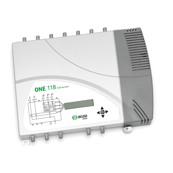
Configuration and setting Introduction General description BI-FM input BIII-DAB input VHF-UHF/EXT input * UHF3 input UHF2 input UHF1 input SAT-IF1 input * Mains connector Control button 10 Screen (LCD) 11 Front panel with cluster map 12 SAT-IF2 input with no amplification * 13 Output 2;... - Page 7 Configuration and setting Reprogrammable as many times as required. 10 tuneable UHF filters with the capacity to process 1 to 5 channels each. Signal processing: Terrestrial inputs with low noise figure (< 6 dB). Satellite input with low noise figure (< 9 dB). Automatic signal level equalisation.
-
Page 8: General Equipment Use
Configuration and setting VHF-UHF/EXT gain = 35 dB (2 outputs) or 40 dB (1 output). SAT1 gain = 40 dB. SAT2 gain = -1.5 dB. Outputs (2 configurable outputs): 2 TV+FI outputs 2 Test outputs VHF output level = 113 dBμV UHF output level = 118 dBμV FI/Sat output level = 116 dBμV 1 TV+FI output... - Page 9 Configuration and setting This symbol is displayed in the manual setting menu. Visually locate it on the LCD screen and see the cluster map on the panel to see which of the 5 equipment clusters is selected. This acronym is displayed in the main menu. Select it to go back to the language selection menu.
-
Page 10: Equipment Installation And Configuration
Configuration and setting Equipment installation and configuration Only the LCD screen and the button are required to configure the equipment. Follow the steps below to install the equipment and configure the different parameters. Installation RISK OF EQUIPMENT DAMAGE BI-FM BIII-DAB UHF3 UHF2 UHF1 SAT1 Mechanical handling of the equipment... -
Page 11: Quick Menu Guide
Configuration and setting Quick menu guide Language selection Manual setting Advanced settings Self-installation Filter allocation to aerials (7-0-3) (9-0-1) (10-0-0) (2-5-3) (2-7-1) Filter Adjustment General gain BI - BII input BIII-DAB input VHF-UHF/EXT UHF output input SAT-IF adjustment Equipment cloning information Lock Input preamps... -
Page 12: Language Selection
Configuration and setting Language selection NOTE Over the following pages, the field locating and selection method is primarily indica- ted by the “vertical button movement” and “press button” icons. However, horizontal button movement can be used to locate and select fields, as indicated in the General equipment use. -
Page 13: Filter Adjustment
Configuration and setting Configuration (7 – 0 – 3) For three antennas: Configuration(2 – 5 – 3) Configuration (2 – 7 – 1) Mast-head amplifier power configuration NOTE Only where a mast-head amplifier is fitted to the antenna. Locate and select the UHF input voltage: VDC, 24 / 12. - Page 14 Configuration and setting Gain configuration NOTE If AUT is selected (recomended), the AGC will try and maintain the output at factory preset level. If M is selected the AGC will maintain the output at the level you have set. Locate and select the gain configuration mode AUT / M.
-
Page 15: Advanced Settings
Configuration and setting SAT-IF output adjustment LNB power configuration NOTE There are 5 different configurations to select polarisation. Locate and select polarisation: No polarisation: LNB, OFF. 18 V with tones: LNB, 18 V. 18 V without tones: LNB, 18 V. r) 13 V with tones: LNB, 13 V. - Page 16 Configuration and setting Filters cloning NOTE Cloning begins automatically after the following steps. Connect two equipments using a coaxial cable in the Test 1 output of each equipment (see position (15) in the illustration in the General Description. On the equipment receiving the information: locate and select MASTER OFF, SLAVE ON.
- Page 17 Configuration and setting Specific equipment information NOTE Information on the equipment, the programme version, the manufacturing date, the number of hours operating, the temperature and the equipment serial number are displayed on the screen. Restore factory values CAUTION This function will mean that all previous configurations will be lost and the factory values will be restored.
-
Page 18: Self-Installation
Configuration and setting Outputs number configuration NOTE You can choose two types of configuration for Outputs No: TV2 & TV1 or TV1. By default your equipment is configured for two outputs (TV1 & TV2). TV2 & TV1 In the advanced menu, located and select OUTPUT CONFIGURATION TV2&TV1. -
Page 19: Maintenance
Configuration and setting Maintenance Equipment care HANDLING THE INSIDE OF THE EQUIPMENT IS FORBIDDEN Do not dismantle or try to repair the equipment, its accessories or its components. This will render the warranty null and void. Do not use the power cable if it is damaged. To disconnect the power cable, pull carefully on the plug and not the cable. -
Page 20: Technical Specifications
Configuration and setting Technical specifications ONE118 models ONE118 Series MODEL REF. ONE118-C69 2853 470 - 862 Frequency range ONE118-C60 2854 470 - 790 47 - 108 174 - 240 (MHz) ONE118-C48 2855 470 - 694 Inputs BI/FM DAB/BIII UHF 3 UHF 2 UHF 1 Input configuration... -
Page 21: Onesat Model
Configuration and setting Technical specifications ONESAT models MODEL REF. ONESAT Series ONESAT-C69 2850 470 - 862 Frequency ONESAT-C60 2851 range 47 - 108 174 - 240 47 - 240 / 470 - 862 470 - 790 950 - 2150 (MHz) ONESAT-C48 2852 470 - 694... -
Page 22: Onehome Model
Configuration and setting Technical specifications ONEHOME models ONEHOME Series MODEL REF. ONEHOME-C69 2856 470 - 862 Frequency range ONEHOME-C60 2857 47 - 108 470 - 790 (MHz) ONEHOME-C48 2858 470 - 694 Inputs BI/FM Input configuration — Number of programmable UHF filters per input 20/40 Gain switchable... -
Page 23: Technical Annex
Configuration and setting Technical annex BROADBAND TERRESTRIAL TV AMPLIFIERS : The RF output levels specified in this catalogue for IMD3=-60 dB (DIN 45004 B) are applicable when 2 analog TV channels are amplified. If, as is usual, more than 2 TV channels are amplified, such levels have to be reduced according to the following table: Number of Channels (n) -
Page 24: Equipment Recycling
Configuration and setting Warranty Notwithstanding any complaints made to the direct vendor of the product, IKUSI offers equipment users a two-year warranty as of the invoice date, which shall become valid on presenting the receipt of purchase. During the warranty period, IKUSI is responsible for any faults arising due to material or manufacturing defects and shall repair the receiver or replace it for another corresponding to the state of technology at that time. -
Page 25: Replacing The Power Supply
Configuration and setting ONE. Replacing the Power Supply fig 1 fig 3 fig 2 fig 5 fig 4 1. Disconnect from the power network 2. Loosen screws T1, T2 and T3 (fig 1). 3. Press the tabs P1 and P2 while sliding the power supply downwards, on its guides (fig 2). - Page 26 Configuration and setting Pº Miramón, 170 20014 San Sebastián - SPAIN Tel.: +34 943 44 88 00 - Fax: +34 943 44 88 20 television@ikusi.com - www.ikusi.tv ONE (en)
Need help?
Do you have a question about the IKUSI ONE Series and is the answer not in the manual?
Questions and answers