
Subscribe to Our Youtube Channel
Related Manuals for Observator Instruments OMC-140

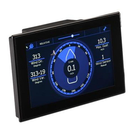
Summary of Contents for Observator Instruments OMC-140
- Page 1 OMC-140 Multifunctional NMEA display Installation Manual Version 1.18 2019 Author: Observator Instruments...
- Page 2 1.16 (March 2019) Added Airport setup. 1.17 (March 2019) Added NMEA TAG information . 1.18 (April 2019) Some updates Disclaimer: Observator Instruments reserves the right to improve their products and therefore specifications might change without prior notice. OMC-140 Installation Manual Page 2...
-
Page 3: Table Of Contents
6.4.3 Rotated wind circle & boat symbol ..................26 6.4.4 Enabling parameters without the actual data ..............27 6.4.5 MeteoLink and OMC-140 ..................... 28 6.4.6 Setting up Airport display ..................... 29 6.4.7 Setting up RAIN (tipping bucket) ..................32 6.4.8 Changing Rain gauge bucket size .................. - Page 4 Menu Structure Terminal Mode ...................... 58 Dimensional drawings ........................65 Panel cut-outs ..........................67 17.1 Recommended panel cut-out ....................67 17.2 Panel cut-out for retrofit 144x144 instrument ................67 17.3 Optional Keypad panel cut-out ....................68 OMC-140 Installation Manual Page 4...
- Page 5 Page intentionally left blank OMC-140 Installation Manual Page 5...
-
Page 6: Introduction
1 Introduction This manual contains required information for installation, commissioning and integrating the OMC-140 display. For operating the display we kindly refer to the Operators’ Guide and Operators’ Manual. Some information will be available in both manuals for your convenience. We do advise to keep the Operators manual at hand as well during installation. -
Page 7: Safety
They do NOT replace your own observations! Note the correct power supply voltage: Do not connect AC power to DC version of display! After end of life dispose this product according local regulations or return to manufacturer. OMC-140 Installation Manual Page 7... -
Page 8: Identification
(mounted on the display) Black 24VDC power connector (mounted on Display) 4 Terminal connector input (mounted on the display) 3 Terminal connector output (mounted on the display) *Either the green (AC) or black (DC) power connector is included. OMC-140 Installation Manual Page 8... -
Page 9: Optional Items
1. Spacer for 144x144 (retrofit) mounting. 2. Bracket 3. Micro USB cable 4. Cleaning kit 5. 12-24 VDC PSU module 6. Remote control panel 7. Micro SD card max 32GB 8. Power connector cable housing OMC-140 Installation Manual Page 9... -
Page 10: Display
3.3 Display Connections are described in chapter 5 Terminals Mounting plate Mounting plate Power Option Board slots Micro SD card slot OMC-140 Installation Manual Page 10... -
Page 11: Option Modules
2. Remove package of option module 3. Position the module with the connector facing the display on the left side and carefully slide the module in the module slot. 4. Secure the module with the screws from the protection plate. OMC-140 Installation Manual Page 11... -
Page 12: Mounting
Secure the display using the 4 Nylon screws, tighten them carefully by hand. If hard to reach a Phillips screwdriver can be used, but do not use any force. No force should be used to tighten the Mounting clamps and Nylon screws! OMC-140 Installation Manual Page 12... -
Page 13: Terminals
5 Terminals 5.1 Sensor connection The OMC-140 display has 2 isolated NMEA inputs, both with power output available. The power outputs have a configurable watchdog option, whenever no valid signal is received for 10s (default setting), the power will be interrupted to reset the attached sensor. -
Page 14: Ac Power Connection
5.3 AC Power Connection The standard OMC-140 Display accepts AC voltages in the range of 100 .. 240VAC @ 45 .. 65 Hz. The connection is meant for panel mount installations. For AC power a green connector is used. Note: For installations where the AC Mains connection is accessible the optional connector cover must be installed! 5.4 DC power connection... -
Page 15: Remote Keypad And Relay Module (Optional)
5.6 Remote keypad and relay module (optional) Left Connector 1 .. 5 Remote Keypad Right connector: Relay outputs Relay 1 NO contact Relay 1 Common Relay 1 NC contact Relay 2 NO contact Relay 2 Common Relay 2 NC contact OMC-140 Installation Manual Page 15... -
Page 16: Connections
Connect the data cable(s) for input and output if required. Connect the keypad (if applicable). Finally connect the power cable. If the AC connector is used Details of the terminal connection can be found in the next chapter. Connection overview OMC-140 Installation Manual Page 16... -
Page 17: Commissioning
The first time the display is started it will give you the option to select the type. Perform a Factory Reset if the display has been configured before and you want to select a different type. The Factory Reset is described in paragraph 6.4 Advanced. OMC-140 Installation Manual Page 17... - Page 18 Display type Specific Features Front tab Vessel graphic for Relative & Theoretical Marine Wind wind display Wind rose graphic for True wind display Land Wind Wind rose graphic Large position field GPS repeater Arrow drift display OMC-140 Installation Manual Page 18...
- Page 19 Lightning display for use Lighting with BTD3xx sensor Airborne wind display with Airport runway graphic. Graphical water depth + Echo Sounder max 6 parameters. Heading 2 Heading display full circle Log speed Log speed gauge OMC-140 Installation Manual Page 19...
- Page 20 Rate Of Turn R.O.T. gauge Demonstration mode, Demo Modus toggle between all available display types. Loads a Filename should be: configuration from the SD card config.dat OMC-140 Installation Manual Page 20...
-
Page 21: Configuration Via Touch Screen
The ‘Advanced’ password is default 1382. This can be changed via the advanced tab. This can be useful when you don’t want the operator to be able to edit the advanced settings. Tap ‘New Pass’ You will be asked to type the current password. OMC-140 Installation Manual Page 21... -
Page 22: Advanced Settings
Code 1382 opens settings for the System Administrator on the ‘Advanced’ page, the ‘Front’ tab and the ‘Sensors’ tab. After editing use the Save & Exit button to save any changes or Cancel to discard them. OMC-140 Installation Manual Page 22... - Page 23 4. Delay is set in seconds. The wind speed will need to be above the set alarm value for the set delay time before it is triggered. 5. Hysteresis is set in wind speed and work when the wind speed goes below the set value. OMC-140 Installation Manual Page 23...
- Page 24 Knots are used as whole Knots (no decimals). Therefore alarms are (de)activated when the wind speed reaches a whole Knot higher or lower than the set value! The other units do use decimals; m/s will result in the highest resolution. OMC-140 Installation Manual Page 24...
-
Page 25: Nmea
6.4.1 NMEA The OMC-140 detects incoming sentences and will add them automatic to the selection list. It will also warn you whenever the sentence is missing (Yellow sensor warning on Front, missing sentences in red op NMEA tab). This is a very useful function when you are configuring the display, but under some conditions you might want to disable it. -
Page 26: Front (Screen Layout)
The wind circle & boat can be rotated in steps of 90°. This useful in case the display is mounted sideways or on the aft. Tap in the middle of the circle to rotate 90° clockwise until the desired position. OMC-140 Installation Manual Page 26... -
Page 27: Enabling Parameters Without The Actual Data
MTW Water Temp. Data (AUTO) VIS Visibility Data (AUTO) CME Cloud Data (AUTO) BTD Lightning Data (AUTO) DBK Depth Data (AUTO) DPT Depth Data (AUTO) VLW Water Distance (AUTO) VBW Water Speed (AUTO) ROT Rate Of Turn (AUTO) OMC-140 Installation Manual Page 27... -
Page 28: Meteolink And Omc-140
It does make some things a little more complex. The OMC-140 is default set to auto configure and will recognize incoming sentences, add them to the input list including the tag id. The display will monitor the input and warn if messages are missing. -
Page 29: Setting Up Airport Display
It is also possible to name the connected wind sensors. The sensor data must have been received by the display in order to change the name! Type ‘B’ to go to the Wind sensor Address & Sensor Name menu: OMC-140 Installation Manual Page 29... - Page 30 Select 1 to change the Name (max 6 characters Please note: the 2 middle parameter positions have only space for 5 characters. So if you use 6 change the wind sensor selection parameter / button to one of the corner positions! OMC-140 Installation Manual Page 30...
- Page 31 Repeat this for the other sensors (if any). OMC-140 Installation Manual Page 31...
-
Page 32: Setting Up Rain (Tipping Bucket)
10s interval). For using the Rain / day parameter the time must be set correct in the OMC-140. If a GPS is connected, it will be corrected automatically, otherwise set the correct time via the USB port in the SD menu (see chapter 7). -
Page 33: Changing Rain Gauge Bucket Size
From the main menu choose: 2 Wind / Meteo Choose: B Wind Sensor Address & Sensor Name Find the pulse input, which will be a sensor address ending on R1 and type XDR (number 6 in this example). OMC-140 Installation Manual Page 33... -
Page 34: Sensors
Confirm with [Enter] Return to main menu by pressing ‘0’ until you are asked to exit. Choose save settings otherwise all changes will be lost. 6.4.9 Sensors This tab shows the VER data of connected sensors. OMC-140 Installation Manual Page 34... -
Page 35: I/O Udp Lan (Nmea Over Ethernet)
This function will give you great flexibility IEC 61162-450 compliant. It will work in combination with the MeteoLink SMART-node, but also with other OMC-140 displays. On the Info tab the Ethernet status can be found: Settings can be done via USB menu:... -
Page 36: Connections Via Udp
Via a router: The easiest way is using a router. Default the OMC-140 has UDP in- & output enabled and the DHCP client is on. Wind data will be transferred via UDP between all OMC-140 displays if a MeteoLink Smart node is in the network its data will also be available. -
Page 37: Data Log Function
* Once SD logging is selected On GGA message is available; time will be daily synchronized with the UTC time. Since date is not in the GGA message this will not be synchronized like the time! OMC-140 Installation Manual Page 37... -
Page 38: Storage
‘SD fault’. On the NMEA tab page the following information is available in the bottom line: SD card status: SD-Card OK Insert SD-Card SD-card missing, not accessible or full Please insert or replace an SD-card OMC-140 Installation Manual Page 38... -
Page 39: Parameters
55.2 ° 10 min Avg maximum true wind gust speed from 10min 15.2 m/s 10 min Avg maximum true wind gust direction from 44.0 ° n.a. 10 min Avg 10min supply voltage 24.2 V n.a. n.a. OMC-140 Installation Manual Page 39... - Page 40 18.8 °C n.a. n.a. VOT : visual observation acquisition trigger n.a. n.a. n.a. Example NMEA AWS sentence: $PEUMB,20120715,090227,52.405,-5.338,192.0,5.2,184.0,997.4,998.6 ,2.3,2,16.0,87.5,,9.4,98.5,12.4,55.2,15.2,44.0,24.2,18.8, -38,,,<CR><LF> OMC-140 Installation Manual Page 40...
-
Page 41: Terminal Mode Configuration
Main Menu: Device Settings Wind / Meteo Settings GPS Settings Heading Settings SD Log Settings Graph Settings Ethernet Settings Exit Menu You can find the full menu structure in chapter 15 Menu Structure Terminal Mode OMC-140 Installation Manual Page 41... -
Page 42: Terms, Abbreviations & Symbols List
Select between Day or Night mode. In Night mode a darker color palette reduces the emitted light intensity. Brightness slider bar. In Automatic or NMEA control mode; use this to set an offset. Settings menu OMC-140 Installation Manual Page 42... -
Page 43: Digital Interface
Air Temperature 10.1.2 Outputs: All recognized input messages (except the retired NMEA sentences) can be copied to the output Calculated messages $xxMWV Relative or Theoretical Wind $xxMWD True Wind Other functions $xxDDC Dimming control of backlight OMC-140 Installation Manual Page 43... -
Page 44: Tag Notes
1 sensor. The TAG “\s:string*hh\” can contains source information of the string. ‘string’ starts with a letter (A= SMART node, B= Basic node & D=OMC-140 Display), followed by the last three digits of its serial number, followed by the input port. -
Page 45: Nmea Udp Protocol
\s: D321G1*hh\ 10.2 NMEA UDP protocol Since the introduction of ML and the OMC-140 version 2.0 the Ethernet UDP stack is functional. Due to regulations (IEC 61162-450) the TAG block implementation is slightly different from the previous described “Meteolink TAGs”. -
Page 46: Udp-Tag Calculation
*it is not possible to transmit a NMEA message over UDP without the ML + UDP-tag information! 10.4 NMEA Message description $--DDC,a,xx,a,a*hh<CR><LF> 1 2 3 4 1. Display dimming preset 2. Brightness percentage 00 to 99 3. Color palette 4. Sentence Status Flag $--GGA,hhmmss.ss,llll.ll,a,yyyyy.yy,a,x,xx,x.x,x.x,M,x.x,M,x.x,xxxx*hh<CR><LF> 4 5 6 1. UTC of position OMC-140 Installation Manual Page 46... - Page 47 4. Standard deviation of semi-minor axis of error ellipse (meters) 5. Orientation of semi-major axis of error ellipse (degrees from true north) 6. Standard deviation of latitude error (meters) 7. Standard deviation of longitude error (meters) 8. Standard deviation of altitude error (meters) OMC-140 Installation Manual Page 47...
- Page 48 5. Unique Identifier 6. Manufacturer serial number 7. Model code (product code) 8. Software revision 9. Hardware revision 10. Sequential message identifier $--VHW,x.x,T,x.x,M,x.x,N,x.x,K*hh<CR><LF> 1. Heading, degrees True 2. Heading, degrees Magnetic 3. Speed, knots 4. Speed, km/hr OMC-140 Installation Manual Page 48...
- Page 49 4 = empty also recognized Dewpoint (Celsius) xx.x Barometric pressure xx.x 4 <> QNH or QFE (Bar) Barometric pressure xx.x (Bar) Barometric pressure xx.x (Bar) Water temperature xx.x 1 = W (4 empty) is also recognized (Celsius) OMC-140 Installation Manual Page 49...
- Page 50 The OMC-140 multifunctional display will also accept the following retired sentences: Note: These messages will only be used for display and not forwarded to the output! $--MDA,x.x,I,x.x,B,x.x,C,x.x,C,x.x,x.x,x.x,C,x.x,T,x.x,M,x.x,N,x.x,M*hh<CR><LF> Barometric pressure, inches of mercury * Barometric pressure, bars * Air temperature, degrees C...
- Page 51 Observator Proprietary Messages $POBSBTD $POBSCBE $POBSVIS OMC-140 Installation Manual Page 51...
-
Page 52: Nmea Hardware
11 NMEA Hardware: Input circuit (simplified) Optical Isolated Output circuit (simplified) OMC-140 Installation Manual Page 52... -
Page 53: Specifications
13.5 Dimming possibilities From 0,5..700 cd/m2 Day and night pallet selectable Manual by means of ‘slider bar’ Automatic by means of ambient light sensor Central by means of NMEA DDC input OMC-140 Installation Manual Page 53... -
Page 54: Dimensions
Weight 3 kgs (incl packing & mounting materials) 13.7 Alarms Build-in alarms on parameters and system functioning Outputs, potential free relay outputs through optional OMC-140-2 module 13.8 In accordance with DNVGL-CG-0339 EMC Directive 2014/30/EU ... -
Page 55: Menu Structure Touch Screen
10 minute 2 minute Instant User (settings from User Average Interval) Wind Speed (Wind only) km/h Wind Reference (Wind only) Relative Theoretical True User Average Interval (Wind only) Wind Speed Wind Direction Gust Wind Variation OMC-140 Installation Manual Page 55... - Page 56 Secure User Items Average (un)lock (Wind only) Wind Speed (un)lock (Wind only) Dimming Control (un)lock Sensor Selection (un)lock Wind Reference (un)lock (Wind only) System Name (GPS only) Edit GPS names (GPS only) Options Displays installed option boards OMC-140 Installation Manual Page 56...
- Page 57 Total Uptime: xxxxx hours UDP Output (ON) Since: dd-mm-yy LAN Link Status (DOWN) Front (only visible in Advanced Menu) Edit data fields in Front screen Sensors (only visible in Advanced Menu) NMEA VER Message Table OMC-140 Installation Manual Page 57...
-
Page 58: Menu Structure Terminal Mode
(AUTO) VBW Water Speed (AUTO) ROT Rate Of Turn (AUTO) Baro Status (AUTO) NMEA Allow No Checksum (OFF) Port 1 & 2 Previous Menu Sensor 2 installation Settings Sensor 2: Watchdog Time Baud rate (4800) OMC-140 Installation Manual Page 58... - Page 59 MDA Combined Data (AUTO) MTW Water Temp. Data (AUTO) VIS Visibility Data (AUTO) CME Cloud Data (AUTO) BTD Lightning Data (AUTO) DBK Depth Data (AUTO) DPT Depth Data (AUTO) VLW Water Distance (AUTO) VBW Water Speed (AUTO) OMC-140 Installation Manual Page 59...
- Page 60 NMEA VIS (Unattended) (OFF) NMEA CME (Unattended) (OFF) NMEA BTD (Unattended) (OFF) Previous Menu NMEA MWV Reference (Relative) Serial Output NMEA MWV References: 1 Relative 2 Theoretical 3 Relative & Theoretical OMC-2900 Wind speed sign OMC-140 Installation Manual Page 60...
- Page 61 Wind Speed Units (kn) Km/h Sensor Selection (Automatic) Automatic Sensor 1 Sensor 2 Wind Reference (True) Relative Theoretical True Offset Sensor 1 (0 degree) Offset Sensor 2 (0 degree) Wind Alarm (OFF) Pre Alarm (10.0 m/s) OMC-140 Installation Manual Page 61...
- Page 62 CAP437 Baro Rule (ON) Multi sensor display (OFF) Gill Fix (OFF) Airport Direction Rounding (ON) Wind Arrow Color (Red) GPS Settings Menu GPS: Sensor Selection (Automatic) Automatic Sensor 1 Sensor 2 Front View 1 (LAT/LON) OMC-140 Installation Manual Page 62...
- Page 63 Front View 2 (User Defined) User Defined SOG View Secure User Items Dimming Control (UNLOCKED) Sensor Selection (UNLOCKED) Front View 1 (UNLOCKED) Front View 2 (UNLOCKED) Set Selectable System Names GNSS#1 GNSS#2 GNSS#3 GNSS#4 GNSS#5 GNSS#6 OMC-140 Installation Manual Page 63...
- Page 64 Menu Graph: Decimals 1 Default 2 -40.0 60.0 Ethernet Settings Menu Ethernet Settings: Ethernet (ON) DHCP Client (OFF) Static IP (192.168.123.48) Static Gateway (192.168.123.1) Static Subnet (255.255.0.0) UDP Input (ON) UDP Output (ON) Exit Menu OMC-140 Installation Manual Page 64...
-
Page 65: Dimensional Drawings
16 Dimensional drawings OMC-140 Installation Manual Page 65... - Page 66 Spacer advised to be used in case of retrofitting into a 144x144 cut-out OMC-140 Installation Manual Page 66...
-
Page 67: Panel Cut-Outs
17 Panel cut-outs 17.1 Recommended panel cut-out 17.2 Panel cut-out for retrofit 144x144 instrument OMC-140 Installation Manual Page 67... -
Page 68: Optional Keypad Panel Cut-Out
17.3 Optional Keypad panel cut-out OMC-140 Installation Manual Page 68...
Need help?
Do you have a question about the OMC-140 and is the answer not in the manual?
Questions and answers