Table of Contents
Advertisement
Available languages
Available languages
Quick Links
Advertisement
Chapters
Table of Contents

Subscribe to Our Youtube Channel
Related Manuals for Moeller ZB65 Series


Summary of Contents for Moeller ZB65 Series
- Page 1 Motorschutzrelais ZB65 und ZB150 Überlastüberwachung von EEx e-Motoren Motor-protective relays ZB65 and ZB150 Overload monitoring of EEx e motors Hardware und Projektierung Hardware and Engineering 07/04 AWB2300-1545D/GB T hink future. Switch to green.
- Page 2 No part of this manual may be reproduced in any form (printed, photocopy, microfilm or any otherprocess) or processed, duplicated or distributed by means of electronic systems without written permission of Moeller GmbH, Bonn. Subject to alterations without notice. Printed on bleached cellulose.
- Page 3 Warnung! Warning! Gefährliche Dangerous elektrische electrical voltage! Spannung! Vor Beginn der Installationsarbeiten Before commencing the installation • Gerät spannungsfrei schalten. • Disconnect the power supply of the device. • Ensure relosing interlock that devices • Gegen Wiedereinschalten sichern. cannot be accidentally restarted. •...
- Page 4 07/04 AWB2300-1545D/GB Überblick/Overview Motorschutzrelais ZB65 und ZB150 Überlastüberwachung von EEx e-Motoren ZB65 and ZB150 motor-protective relays Overload monitoring of EEx e motors Anhang/Appendix...
-
Page 5: Table Of Contents
07/04 AWB2300-1545D/GB Inhalt Zu diesem Handbuch Zielgruppe Abkürzungen und Symbole Motorschutzrelais ZB65 und ZB150 Vorwort Geräteübersicht Gerätebeschreibung – Überlastschutz mit Bimetallrelais – Strombereiche der Motorschutzrelais – Temperaturkompensation – Phasenausfall – Wiedereinschaltung – Testfunktion Projektierung Überlastüberwachung von Motoren im EEx e-Bereich Einstellung der Überstromschutzeinrichtung –... - Page 6 07/04 AWB2300-1545D/GB Inhalt Anhang/Appendix Typenschilder/Rating plates – Motorschutzrelais/Overload relay ZB65 – Motorschutzrelais/Overload relay ZB150 Auslösekennlinien/ Tripping characteristics – ZB65-10 – ZB65-16 – ZB65-24 – ZB65-40 – ZB65-57 – ZB65-65 – ZB150-35, ZB150-35KK – ZB150-50 – ZB150-50KK – ZB150-70, ZB150-70KK – ZB150-100 –...
-
Page 7: Zu Diesem Handbuch
07/04 AWB2300-1545D/GB Zu diesem Handbuch Das vorliegende Handbuch gilt für die Motorschutzrelais ZB65 und ZB150. Dieses Handbuch beschreibt die Überlastüberwachung zum Schutz von EEx e-Motoren in explosiongefährdeten Berei- chen. Zielgruppe Dieses Handbuch richtet sich an Fachpersonal, das die Motorschutzrelais installiert, in Betrieb nimmt und wartet. Abkürzungen und Symbole In diesem Handbuch werden Abkürzungen und Symbole eingesetzt, die folgende Bedeutung haben: EEx e... - Page 8 07/04 AWB2300-1545D/GB Zu diesem Handbuch Warnung! warnt vor schweren Sachschäden und schweren Verletzungen oder Tod. Für eine gute Übersichtlichkeit finden Sie auf den linken Seiten im Kopf die Kapitelüberschrift und auf den rechten Seiten den aktuellen Abschnitt, Ausnahmen sind Kapitel- anfangsseiten und leere Seiten am Kapitelende.
-
Page 9: Motorschutzrelais Zb65 Und Zb150
07/04 AWB2300-1545D/GB Motorschutzrelais ZB65 und ZB150 Vorwort Für den Schutz von Motoren in explosionsgefährdeten Bereichen gelten zusätzlich zu den Vorschriften nach EN 60079-14 und VDE 0165 Teil 1 separate Vorschriften für die entsprechenden Zündschutzarten. Für Motoren in der Zündschutzart „e“ „Erhöhte Sicherheit“ verlangt die Vorschrift EN 50019 zusätzliche Maßnahmen. -
Page 10: Geräteübersicht
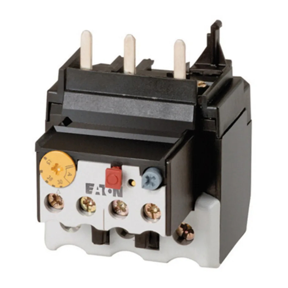
07/04 AWB2300-1545D/GB Motorschutzrelais ZB65 und ZB150 Geräteübersicht Abbildung 1: Motorschutzrelais ZB65 Abbildung 2: Motorschutzrelais ZB150 Abbildung 3: Motorschutzrelais ZB150-…KK... -
Page 11: Gerätebeschreibung
07/04 AWB2300-1545D/GB Gerätebeschreibung Gerätebeschreibung Überlastschutz mit Bimetallrelais Die Motorschutzrelais ZB65 und ZB150 sind dreipolige elek- tromechanische Motorschutzrelais mit Bimetallen. Sie sind zur Überwachung von Gleich- und Wechselstrom geeignet. Die Motorschutzrelais ZB65 und ZB150 sind als Direktanbau an die Schütze DIL einsetzbar. Direktanbau Motorschutzrelais Schütz... -
Page 12: Strombereiche Der Motorschutzrelais
07/04 AWB2300-1545D/GB Motorschutzrelais ZB65 und ZB150 L1 L2 L3 (Q11/1) -S11 -Q11 -Q11 U V W Abbildung 4: Schaltbild eines Motorabganges mit Motorschutzrelais Sicherung Motorschutzrelais Motorschütz Motor Strombereiche der Motorschutzrelais Die Z-Relais werden mit Hilfe der Strom-Einstellscheibe auf den Motornennstrom eingestellt. Mit verschiedenen Typen können Motoren von 10 bis 150 A Motornennstrom überwacht werden. - Page 13 07/04 AWB2300-1545D/GB Gerätebeschreibung Tabelle 1: Strombereiche ZB65 Relais Strombereich I [A] ZB65-10 6 bis 10 ZB65-16 10 bis 16 ZB65-24 16 bis 24 ZB65-40 24 bis 40 ZB65-57 40 bis 57 ZB65-65 50 bis 65 Tabelle 2: Strombereiche ZB150 Relais Strombereich I [A] ZB150-35 25 bis 35...
-
Page 14: Temperaturkompensation
07/04 AWB2300-1545D/GB Motorschutzrelais ZB65 und ZB150 Temperaturkompensation Zwei Parameter beeinflussen die Ausbiegung der Bimetalle. Zum einen ist das die Wärme, die proportional zum flie- ßenden Strom erzeugt wird und zum anderen ist das der Einfluss der Umgebungstemperatur. Der Einfluss der Umgebungstemperatur wird mit Hilfe eines zusätzlichen Bimetalls, das nicht vom Motorstrom durch- flossen wird, im Temperaturbereich –5 °C bis +55 °C konti- nuierlich durch Korrektur des Auslöseweges selbsttätig... -
Page 15: Wiedereinschaltung
07/04 AWB2300-1545D/GB Gerätebeschreibung Soll mit einem ZB65 oder ZB150 Relais ein Wechselstrom- motor oder ein Gleichstrommotor überwacht werden, muss der Strom über alle drei Strombahnen geführt werden, um Frühauslösungen zu vermeiden. Abbildung 6: Verdrahtung der Motorschutzrelais für den Schutz von Wechselstrom- oder Gleichstrommotoren (Reihenschaltung der Bimetallauslöser) (a Abschnitt „Auslösekennlinien“... -
Page 16: Testfunktion
07/04 AWB2300-1545D/GB Motorschutzrelais ZB65 und ZB150 Testfunktion Durch eine zusätzliche Testtaste kann die Funktionstüchtig- keit der Hilfsschalter kontrolliert werden. Hierbei hat die Testtaste eine Doppelfunktion: • Das Drücken der Testtaste öffnet den Öffner 95-96. Nach dem Loslassen fällt der Öffner wieder zurück. Diese Funktion kann zum manuellen Ausschalten des Motors genutzt werden. -
Page 17: Projektierung
07/04 AWB2300-1545D/GB Projektierung Überlastüberwachung von Durch besondere konstruktive Maßnahmen erreicht man bei Motoren im EEx e-Bereich Motoren die Zündschutzart EEx e. Die Motoren werden auf Basis der höchst zulässigen Oberflächentemperaturen Temperaturklassen zugeordnet. Zusätzlich wird die Erwär- mungszeit t und das Verhältnis Anlaufstrom zu Nennstrom bestimmt und auf dem Motor angegeben. - Page 18 07/04 AWB2300-1545D/GB Projektierung Beispiel: I = 6, t = 10 s 7 8 9 10 Abbildung 7: Auslösekennlinie des Motorschutzrelais Der Motor wird zuverlässig geschützt.
-
Page 19: Kurzschlussschutz Der Motorschutzrelais
07/04 AWB2300-1545D/GB Einstellung der Über- stromschutzeinrichtung Kurzschlussschutz der Motorschutzrelais Der Kurzschlussschutz der Motorschutzrelais wird durch Sicherungen realisiert. Bei Direktanbau an ein Schütz wird die Vorsicherung des Schützes für die entsprechende Zuord- nungsart mit berücksichtigt. Vorsicht! Zum Schutz von EEx e-Motoren ist nur die Zuordnungsart „2“... -
Page 20: Zulassungen
07/04 AWB2300-1545D/GB Projektierung Tabelle 5: ZB150 in Einzelaufstellung Sicherung gG/gL [A] Zuordnungsart „1“ Zuordnungsart „2“ ZB150-35KK ZB150-50KK ZB150-70KK ZB150-100KK ZB150-125KK ZB150-150KK 1) nach IEC/EN 60947 Zulassungen Die Motorschutzrelais ZB65, ZB150 und ZB150-…KK sind nach der Vorschrift IEC EN 60947 Niederspannungsschalt- geräte gebaut und erfüllen die Forderungen nach der Richt- linie 94/9/EG (ATEX 100a) zum Schutz von EEx e-Motoren. -
Page 21: Installation
07/04 AWB2300-1545D/GB Installation Hinweise zur Installation Bei der mechanischen und elektrischen Installation ist die entsprechende Montageanweisung zu beachten. Die Monta- geanweisung liegt den ZB150 Relais bei und ist bei den ZB65 Relais auf der Innenseite der Kartonverpackung aufgedruckt. ZB65: AWA2300-2113 ZB150: AWA2300-2115 Warnung! Für den Explosionsschutz ist nur ein manuelles Rück-... - Page 22 07/04 AWB2300-1545D/GB Installation L1 L2 L3 (Q11/1) -S11 -Q11 -Q11 U V W Abbildung 8: Schaltung verhindert automatischen Wiederanlauf F1 Sicherung F2 Motorschutzrelais Q11 Leistungsschütz M1 Motor Die Selbsthaltung des Leistungsschützes Q11 verhindert einen automatischen Wiederanlauf.
-
Page 23: Geräte Montieren
07/04 AWB2300-1545D/GB Geräte montieren Geräte montieren Die Motorschutzrelais ZB65 können sowohl direkt am Schütz montiert als auch in Kombination mit der Einzelaufstellung aufgebaut werden. Die ZB150 Relais sind für den Direktanbau an das Schütz gebaut, die ZB150-…KK werden einzeln aufgestellt. Tabelle 6: Direktanbau Schütz... - Page 24 07/04 AWB2300-1545D/GB Installation ZB65-XEZ DIL... ZB65 ZB65 Abbildung 9: Montage ZB65 Die Einzelaufstellungen ZB65-XEZ können auf einer Hutschiene oder direkt auf der Montageplatte montiert werden. DIL... ZB150-... Abbildung 10: Montage ZB150...
- Page 25 07/04 AWB2300-1545D/GB Geräte montieren Die ZB150-…KK werden direkt auf die Montageplatte montiert. Tabelle 8: Maße zur Montage ZB65-XEZ ZB150-…KK Bohrmaße (B x H) [mm] 50 x 75 100 x 74 Schraube [mm] 2 x (M5 x 12) 2 x (M6 x 20) Verdrahten Sie die Motorleitungen wie in Abb.
- Page 26 07/04 AWB2300-1545D/GB Installation Hauptstrombahnen Hilfsstrom- bahnen ZB65 ZB150 95-96, 97-98 – 1 x (6 x16 x 0,8) – – 2 x (6 x 16 x 0,8) – [mm] 1 x (14 – 2) 1 x (6 – 2/0) 1 x (18 – 12) 2 x (14 –...
-
Page 27: Geräte Betreiben
07/04 AWB2300-1545D/GB Geräte betreiben Einstellungen Vor der Erstinbetriebnahme des Motorschutzrelais muss der Motornennstrom mit Hilfe einer Stromeinstellscheibe am Relais eingestellt werden (a Tabelle 1 und Tabelle 2 auf Seite 9). Rücksetzung Die Motorschutzrelais ZB65 und ZB150 bieten mit Hilfe des Wahlknopfes Reset die Möglichkeit, zwischen einem auto- matischem Wiederanlauf „A“... -
Page 28: Test
07/04 AWB2300-1545D/GB Geräte betreiben Test Die Motorschutzrelais ZB65 und ZB150 sind mit einer Taste Test versehen, in der eine Doppelfunktion integriert ist. TEST NO 97 NC 95 NO 98 NC 96 Abbildung 13: Schaltmöglichkeiten der Taste Test Ein Ziehen der Taste hat das Öffnen des Hilfskontaktes 95-96 zur Folge und kann zum Abschalten des Schützes genutzt werden. - Page 29 07/04 AWB2300-1545D/GB Contents About this manual Target group Abbreviations and symbols Motor-protective relays ZB65 and ZB150 Preface Overview of the devices Device description – Overload protection relays with bimetallic release – Current ranges of the motor-protective relays – Temperature compensation –...
- Page 30 07/04 AWB2300-1545D/GB Contents Anhang/Appendix Typenschilder/Rating plates – Motorschutzrelais/Overload relay ZB65 – Motorschutzrelais/Overload relay ZB150 Auslösekennlinien/ Tripping characteristics – ZB65-10 – ZB65-16 – ZB65-24 – ZB65-40 – ZB65-57 – ZB65-65 – ZB150-35, ZB150-35KK – ZB150-50 – ZB150-50KK – ZB150-70, ZB150-70KK – ZB150-100 –...
-
Page 31: About This Manual
07/04 AWB2300-1545D/GB About this manual This manual applies to the motor-protective relays ZB65 and ZB150. It describes the overload monitoring system for the protection of motors operating in potentially explosive atmospheres EEx e areas. Target group This manual addresses special personnel who install, commission and service the motor-protective relay. - Page 32 07/04 AWB2300-1545D/GB About this manual Warning! Warns of the risk of heavy material damage and of serious or lethal injury. The chapter title in the header on the left side and the title of the current topic on the right side provide you with a good overview of this documentation.
-
Page 33: Motor-Protective Relays Zb65 And Zb150
07/04 AWB2300-1545D/GB Motor-protective relays ZB65 and ZB150 Preface In addition to the type of protection specified in the standards EN 60079-14 and VDE 0165 Part 1, further provisions have been made to enrue the safety from ignition for motors operated in potentially explosive atmospheres. EN 50019 demands additional measures for operating motors with "increased safety"... -
Page 34: Overview Of The Devices
07/04 AWB2300-1545D/GB Motor-protective relays ZB65 and ZB150 Overview of the devices Figure 1: Motor-protective relay ZB65 Figure 2: Motor-protective relay ZB150 Figure 3: Motor-protective relay ZB150-…KK... -
Page 35: Device Description
07/04 AWB2300-1545D/GB Device description Device description Overload protection relays with bimetallic release The overload relays ZB65 and ZB150 are 3-pole electromechanical motor-protective relays and are equipped with bimetallic releases. They are suitable both for AC and for DC operation. The motor-protective relays ZB65 and ZB150 can be mounted directly onto DIL contactor relays. -
Page 36: Current Ranges Of The Motor-Protective Relays
07/04 AWB2300-1545D/GB Motor-protective relays ZB65 and ZB150 L1 L2 L3 (Q11/1) -S11 -Q11 -Q11 U V W Figure 4: Circuit diagram of a motor tap with motor-protective relay Fuse Motor-protective relay Motor contactor Motor Current ranges of the motor-protective relays The rated motor current is set on the Z relays by means of a current setting dial. - Page 37 07/04 AWB2300-1545D/GB Device description Table 1: Current ranges of ZB65 relays Type Current range I [A] ZB65-10 6 to 10 ZB65-16 10 to 16 ZB65-24 16 to 24 ZB65-40 24 to 40 ZB65-57 40 to 57 ZB65-65 50 to 65 Table 2: Current ranges of ZB150 relays Type...
-
Page 38: Temperature Compensation
07/04 AWB2300-1545D/GB Motor-protective relays ZB65 and ZB150 Temperature compensation Two parameters influence the deflection of the bimetallic releases. There is for one the heat which is generated in proportion to the current flow, and secondly, the influence of the ambient temperature. The influence of the ambient temperature is automatically compensated within a temperature range from -5 °C to +55 °C by means of an additional current-free bimetallic... -
Page 39: Reset
07/04 AWB2300-1545D/GB Device description When a ZB65 or ZB150 relay is to be used for monitoring an AC or DC motor, the current must flow across all three current paths in order to avoid early tripping. Figure 6: Wiring of the motor-protective relay for the protection of AC or DC motors (bimetallic release switched in series) (a Section "Tripping characteristics"... -
Page 40: Test Function
07/04 AWB2300-1545D/GB Motor-protective relays ZB65 and ZB150 Test function The function of the auxiliary contacts can be verified by means of an additional test button that has a dual function: • When the button is pressed, the break contact 95-96 opens. -
Page 41: Configuration
07/04 AWB2300-1545D/GB Configuration Monitoring overload of The "EEx e" type of protection for motors is achieved by motors in the EEx e area means of special constructive measures. The motors are assigned to temperature classes based on the maximum permitted surface temperatures. The temperature rise time t and the ratio between startup current and rated current I are calculated also and specified on the rating plate of the motor. - Page 42 07/04 AWB2300-1545D/GB Configuration Example: I = 6, t = 10 s 7 8 9 10 Figure 7: Tripping characteristics of the motor-protective relay The motor is reliably protected.
-
Page 43: Short-Circuit Protection Of The Motor-Protective Relays
07/04 AWB2300-1545D/GB Adjusting the overload current protection Short-circuit protection of the motor-protective relays The motor-protective relays are short-circuit protected by means of fuses. When the relay is mounted directly onto a contactor relay, the correpsonding primary fuse of the contactor relay is taken into account accordingly. Caution! Only type "2"... -
Page 44: Approvals
07/04 AWB2300-1545D/GB Configuration Table 5: Individual installation of the ZB150 Fuse gG/gL [A] Type of assignment "1" Type of assignment "2" ZB150-35KK ZB150-50KK ZB150-70KK ZB150-100KK ZB150-125KK ZB150-150KK 1) to IEC/EN 60947 Approvals The motor-protective relays ZB65, ZB150 and ZB150-…KK are compliant with IEC EN 60947 regulations for low-voltage switchgear and meet the requirements of the 94/9/EU (ATEX 100a) directives for the protection of EEx e motors. -
Page 45: Installation
07/04 AWB2300-1545D/GB Installation Notes on installation The mechanical and electrical installation instructions must be observed. The installation instructions are included with the ZB150 relays. For the ZB65 relays, these instructions are imprinted on the inside of the cardboard packing. ZB65: AWA2300-2113 ZB150: AWA2300-2115 Warning! - Page 46 07/04 AWB2300-1545D/GB Installation L1 L2 L3 (Q11/1) -S11 -Q11 -Q11 U V W Figure 8: The circuit prevents an automatic restart. Fuse Motor-protective relay Q11 Contactor relay M1 Motor The latching function of the Q11 contactor relay prevents an automatic restart.
-
Page 47: Mounting The Devices
07/04 AWB2300-1545D/GB Mounting the devices Mounting the devices The motor-protective relays ZB65 can either be mounted directly onto the contactor relay, or in combination with the single-mount assembly. The ZB150 relays are designed for direct mounting to the contactor, whereas the ZB150-…KK series are installed individually. - Page 48 07/04 AWB2300-1545D/GB Installation ZB65-XEZ DIL... ZB65 ZB65 Figure 9: Mounting the ZB65 The single-mount assemblies ZB65-XEZ can be mounted individually on DIN rail or directly on a mounting panel. DIL... ZB150-... Figure 10: Mounting the ZB150...
- Page 49 07/04 AWB2300-1545D/GB Mounting the devices The ZB150-…KK series are mounted directly on a mounting panel. Table 8: Mounting dimensions ZB65-XEZ ZB150-…KK Bore dimensions 50 x 75 100 x 74 (W x H) [mm] Screw [mm] 2 x (M5 x 12) 2 x (M6 x 20) Connect the motor cables as shown in Fig.
- Page 50 07/04 AWB2300-1545D/GB Installation Mains circuit Auxiliary voltage circuit ZB65 ZB150 95-96, 97-98 – 1 x (6 x16 x 0.8) – – 2 x (16 x 6 x 0.8) – [mm] 1 x (14 – 2) 1 x (6 – 2/0) 1 x (18 –...
-
Page 51: Operating The Devices
07/04 AWB2300-1545D/GB Operating the devices Settings Prior to initial commissioning, the rated motor current must be set on the motor-protective relay by means of the current dial (a Table 1 to Table 2 as of Page 33). Reset The user can select automatic restart "A" or manual reset "H"... -
Page 52: Test
07/04 AWB2300-1545D/GB Operating the devices Test The motor-protective relays ZB65 and ZB150 are equipped with a test button that has an integral dual function. TEST NO 97 NC 95 NO 98 NC 96 Figure 13: Switching options of the test button The auxiliary contact 95-96 is opened by pulling the button, and can thus be used to switch off the contactor relay. -
Page 53: Anhang/Appendix
07/04 AWB2300-1545D/GB Anhang/Appendix Typenschilder/Rating Motorschutzrelais/Overload relay ZB65 plates imp 6000 V "1" A gL e 690 V h "2" Normal Test 380/415 500Vh AC–15 220/240 95–96: 0,8 A 97–98: 0,5 A imp 6000 V th 6 A II(2)GD 0102 PTB 04 ATEX 3022 A014079 IEC/EN 60947 Abbildung/Figure 14: Typenschild... - Page 54 07/04 AWB2300-1545D/GB Anhang/Appendix Tabelle/Table 10: Werte der einzelnen Typen/Values of the various types ZB65-10 6 – 10 A ZB65-16 10 – 16 A ZB65-24 16 – 24 A ZB65-40 24 – 40 A ZB65-57 40 – 57 A ZB65-65 50 – 65 A...
-
Page 55: Motorschutzrelais/Overload Relay Zb150
07/04 AWB2300-1545D/GB Typenschilder/Rating plates Motorschutzrelais/Overload relay ZB150 imp 8000 V "1" A gL 1000 V h "2" Normal Test AC–15 380/415 500Vh 220/240 95–96: 0,8 A 97–98: 0,5 A imp 6000 V th 6 A II(2)GD 0102 PTB 04 ATEX 3022 IEC/EN 60947 IND. - Page 56 07/04 AWB2300-1545D/GB Anhang/Appendix Die Zuordnungen der Werte zu den jeweiligen Typen sind der nachfolgenden Tabelle 11 zu entnehmen. For information on the assignment of values to the relevant types, please refer to Tabelle 11. Tabelle/Table 11: Werte der einzelnen Typen/Values of the various types ZB150-35 25 –...
-
Page 57: Auslösekennlinien Tripping Characteristics
07/04 AWB2300-1545D/GB Auslösekennlinien/ Tripping characteristics Auslösekennlinien/ Tripping characteristics... -
Page 58: Zb65-10
07/04 AWB2300-1545D/GB Anhang/Appendix ZB65-10 Bereich/Range 6 – 10 A (NM – HM) Umgebungstemperatur/Ambient temperature 20 °C Auslöseklasse/Tripping class 10 A Toleranzbereich/Tolerance range g 20 % Einstellung/ Auslösezeit/Tripping time t [s] Setting 3-phase a 2-phase c 3-phase b 2-phase d 3 x I 16.5 7.2 x I 7 8 9 10... -
Page 59: Zb65-16
07/04 AWB2300-1545D/GB Auslösekennlinien/ Tripping characteristics ZB65-16 Bereich/Range 10 – 16 A (NM – HM) Umgebungstemperatur/Ambient temperature 20 °C Auslöseklasse/Tripping class 10 A Toleranzbereich/Tolerance range g 20 % Einstellung/ Auslösezeit/Tripping time t [s] Setting 3-phase a 2-phase c 3-phase b 2-phase d 3 x I 29.7 7.2 x I... -
Page 60: Zb65-24
07/04 AWB2300-1545D/GB Anhang/Appendix ZB65-24 Bereich/Range 16 – 24 A (NM – HM) Umgebungstemperatur/Ambient temperature 20 °C Auslöseklasse/Tripping class 10 A Toleranzbereich/Tolerance range g 20 % Einstellung/ Auslösezeit/Tripping time t [s] Setting 3-phase a 2-phase c 3-phase b 2-phase d 3 x I 24.5 7.2 x I 7 8 9 10... -
Page 61: Zb65-40
07/04 AWB2300-1545D/GB Auslösekennlinien/ Tripping characteristics ZB65-40 Bereich/Range 24 – 40 A (NM – HM) Umgebungstemperatur/Ambient temperature 20 °C Auslöseklasse/Tripping class 10 A Toleranzbereich/Tolerance range g 20 % Einstellung/ Auslösezeit/Tripping time t [s] Setting 3-phase a 2-phase c 3-phase b 2-phase d 3 x I 23.5 18.2... -
Page 62: Zb65-57
07/04 AWB2300-1545D/GB Anhang/Appendix ZB65-57 Bereich/Range 40 – 57 A (NM – HM) Umgebungstemperatur/Ambient temperature 20 °C Auslöseklasse/Tripping class 10 A Toleranzbereich/Tolerance range g 20 % Einstellung/ Auslösezeit/Tripping time t [s] Setting 3-phase a 2-phase c 3-phase b 2-phase d 3 x I 28.8 16.6 7.2 x I... -
Page 63: Zb65-65
07/04 AWB2300-1545D/GB Auslösekennlinien/ Tripping characteristics ZB65-65 Bereich/Range 50 – 65 A (NM – HM) Umgebungstemperatur/Ambient temperature 20 °C Auslöseklasse/Tripping class 10 A Toleranzbereich/Tolerance range g 20 % Einstellung/ Auslösezeit/Tripping time t [s] Setting 3-phase a 2-phase c 3-phase b 2-phase d 3 x I 26.4 18.5... -
Page 64: Zb150-35, Zb150-35Kk
07/04 AWB2300-1545D/GB Anhang/Appendix ZB150-35, ZB150-35KK Bereich/Range 25 – 35 A (NM – HM) Umgebungstemperatur/Ambient temperature 20 °C Auslöseklasse/Tripping class 10 A Toleranzbereich/Tolerance range g 20 % Einstellung/ Auslösezeit/Tripping time t [s] Setting 3-phase a 2-phase c 3-phase b 2-phase d 3 x I 7.2 x I 7 8 9 10... -
Page 65: Zb150-50
07/04 AWB2300-1545D/GB Auslösekennlinien/ Tripping characteristics ZB150-50 Bereich/Range 35 – 50 A (NM – HM) Umgebungstemperatur/Ambient temperature 20 °C Auslöseklasse/Tripping class 10 A Toleranzbereich/Tolerance range g 20 % Einstellung/ Auslösezeit/Tripping time t [s] Setting 3-phase a 2-phase c 3-phase b 2-phase d 3 x I 15.8 13.8... -
Page 66: Zb150-50Kk
07/04 AWB2300-1545D/GB Anhang/Appendix ZB150-50KK Bereich/Range 36 – 50 A (NM – HM) Umgebungstemperatur/Ambient temperature 20 °C Auslöseklasse/Tripping class 10 A Toleranzbereich/Tolerance range g 20 % Einstellung/ Auslösezeit/Tripping time t [s] Setting 3-phase a 2-phase c 3-phase b 2-phase d 3 x I 12.8 7.2 x I 7 8 9 10... -
Page 67: Zb150-70, Zb150-70Kk
07/04 AWB2300-1545D/GB Auslösekennlinien/ Tripping characteristics ZB150-70, ZB150-70KK Bereich/Range 50 – 70 A (NM – HM) Umgebungstemperatur/Ambient temperature 20 °C Auslöseklasse/Tripping class 10 A Toleranzbereich/Tolerance range g 20 % Einstellung/ Auslösezeit/Tripping time t [s] Setting 3-phase a 2-phase c 3-phase b 2-phase d 3 x I 15.3... -
Page 68: Zb150-100
07/04 AWB2300-1545D/GB Anhang/Appendix ZB150-100 Bereich/Range 70 – 100 A (NM – HM) Umgebungstemperatur/Ambient temperature 20 °C Auslöseklasse/Tripping class 10 A Toleranzbereich/Tolerance range g 20 % Einstellung/ AuslösezeitTripping time t [s] Setting 3-phase a 2-phase c 3-phase b 2-phase d 3 x I 7.2 x I 7 8 9 10 Abbildung/Figure 26: ZB150-100... -
Page 69: Zb150-100Kk
07/04 AWB2300-1545D/GB Auslösekennlinien/ Tripping characteristics ZB150-100KK Bereich/Range 70 – 1000 A (NM – HM) Umgebungstemperatur/Ambient temperature 20 °C Auslöseklasse/Tripping class 10 A Toleranzbereich/Tolerance range g 20 % Einstellung/ Auslösezeit/Tripping time t [s] Setting 3-phase a 2-phase c 3-phase b 2-phase d 3 x I 7.2 x I 7 8 9 10... -
Page 70: Zb150-125, Zb150-125Kk
07/04 AWB2300-1545D/GB Anhang/Appendix ZB150-125, ZB150-125KK Bereich/Range 95 – 125 A (NM – HM) Umgebungstemperatur/Ambient temperature 20 °C Auslöseklasse/Tripping class 10 A Toleranzbereich/Tolerance range g 20 % Einstellung/ Auslösezeit/Tripping time t [s] Setting 3-phase a 2-phase c 3-phase b 2-phase d 3 x I 24.5 7.2 x I... -
Page 71: Zb150-150
07/04 AWB2300-1545D/GB Auslösekennlinien/ Tripping characteristics ZB150-150 Bereich/Range 120 – 150 A (NM – HM) Umgebungstemperatur/Ambient temperature 20 °C Auslöseklasse/Tripping class 10 A Toleranzbereich/Tolerance range g 20 % Einstellung/ Auslösezeit/Tripping time t [s] Setting 3-phase a 2-phase c 3-phase b 2-phase d 3 x I 7.2 x I 7 8 9 10... -
Page 72: Zb150-150Kk
07/04 AWB2300-1545D/GB Anhang/Appendix ZB150-150KK Bereich/Range 120 – 150 A (NM – HM) Umgebungstemperatur/Ambient temperature 20 °C Auslöseklasse/Tripping class 10 A Toleranzbereich/Tolerance range g 20 % Einstellung/ Auslösezeit/Tripping time t [s] Setting 3-phase a 2-phase c 3-phase b 2-phase d 3 x I 7.2 x I 7 8 9 10 Abbildung/Figure 30: ZB150-150KK... -
Page 73: Konformitätserklärung/Declaration Of Conformity
07/04 AWB2300-1545D/GB Konformitätserklärung/Decla- ration of Conformity Konformitätserklärung/ ZB65-… Declaration of Conformity... -
Page 74: Zb150
07/04 AWB2300-1545D/GB Anhang/Appendix ZB150-…... - Page 75 Industrieautomation Hein-Moeller-Straße 7–11 D-53115 Bonn E-Mail: info@moeller.net Internet: www.moeller.net © 2004 by Moeller GmbH Subjekt to alteration AWB2300-1545D/GB Doku/Doku/Eb 07/04 Printed in Germany (11/06) Article No.: 102065 4 * p a t p k a # - y . v y - *...
Need help?
Do you have a question about the ZB65 Series and is the answer not in the manual?
Questions and answers