Table of Contents
Advertisement
Quick Links
Advertisement
Table of Contents

Related Manuals for Essilor Pro-B 300


Summary of Contents for Essilor Pro-B 300
- Page 1 User Manual...
-
Page 3: Table Of Contents
> C ANUAL ONTENTS ONTENTS NTRODUCTION I. F IRST STEPS 1. Descriptive diagrams 2. Instructions for use a. Turning on device b. Turn off the device c. Using the touch screen and keypads d. Tracing screen II. T RACING 1. The tracing environment a. - Page 4 > C ANUAL ONTENTS IV. M ODIFYING THE LENS SHAPE 1. Legend screen 2. Modifying a shape a. Enlarging, reducing or rotating a shape b. Free-form modification c. Retouching a shape 3. Archiving / saving a shape V. P REPARING A DRILLED JOB 1.
- Page 5 > C ANUAL ONTENTS 2. Environment ENERAL INFORMATION 1. Symbols 2. Modifications 3. Declaration of conformity 4. Copyright 5. Materials and products 6. Safety instructions: 7. Electromagnetic waves LOSSARY...
-
Page 7: Introduction
> I ANUAL NTRODUCTION NTRODUCTION To take full advantage of the features of your Pro-B 300 tracer-centerer-blocker or centerer-blocker, we strongly recommend that you read the documentation. Pro-B 300 > v1.0 - 03.19... -
Page 9: First Steps
I. F IRST STEPS... -
Page 10: Descriptive Diagrams
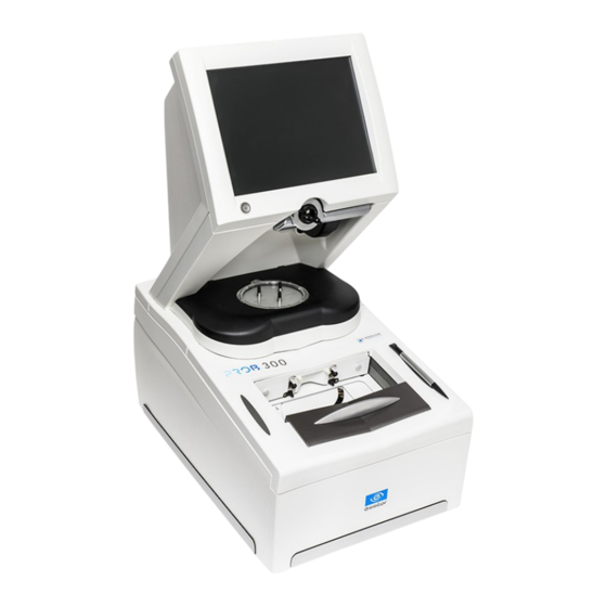
This section contains descriptions and a list of accessories for the tracer-centerer-blocker and centerer- blocker. Tracer-centerer-blocker Screen ON/OFF button Blocking arm Centering chamber Tripod Tracing table (according to version) Blocking head Stylus rest Tripod rest Manufacturer plate USB port Connectors Pro-B 300 > v1.0 - 03.19... - Page 11 Roll of 22 mm pads • Roll of 18x14 mm pads Maintenance accessories • Calibration posiblock • Pro-B 300 specific metal pattern gauge with table • Pro-B 300 specific frame gauge (Black, Numbered) with Table Pro-B 300 > v1.0 - 03.19...
-
Page 12: Instructions For Use
> I. F ANUAL IRST STEPS • Pro-B 300 specific calibration gauge data USB Key with Table Options • Barcode reader • Roll of barcode labels • Start Pedal Connection accessories • Power cable • RJ45 cable for the tracer-edger connection •... -
Page 13: Using The Touch Screen And Keypads
The numeric keypad is displayed for entering values. • Reset the fields • Go back • Confirm • Cancel and go back to the work screen • The alphanumeric keypad is displayed to save or search for jobs. Pro-B 300 > v1.0 - 03.19... -
Page 14: Tracing Screen
IRST STEPS • Job ID • Job reference (alphanumeric characters) • Job list & • Collection list d. Tracing screen Tracer-centerer-blocker Main menus on the tracer-centerer-blocker screen: Work screen indicator Job information Settings Connected devices Pro-B 300 > v1.0 - 03.19... -
Page 15: Tracing
Function buttons ◦ Machine shutdown. ◦ Tracing ◦ Centering ◦ Shape management Actions available for the current screen Tracing cycle initialization Centerer-blocker Blocker screen main menus: Work screen indicator Job information Settings Connected devices Pro-B 300 > v1.0 - 03.19... - Page 16 ◦ Tracing ◦ Centering ◦ Shape management Actions available for the current screen Tracing cycle initialization Detailed functions For more information, consult the section Perform a trace > Tracing environment > Legend screen. p.18) Pro-B 300 > v1.0 - 03.19...
-
Page 17: Ii. T Racing
II. T RACING... -
Page 18: The Tracing Environment
Displaying the tracing completed in binocular mode p.22) a. Legend screen Tracer-centerer-blocker Dimensions display ◦ A: A-dimension ◦ B: B-dimension ◦ D: D-dimension ◦ E: Larger radius from the Boxing center ◦ P: Perimeter Function buttons ◦ Tracing Pro-B 300 > v1.0 - 03.19... - Page 19 Groove detection ◦ : insertion in the middle of the frame (default value), ◦ : high insertion (up to 75% the height frame), ◦ : low insertion (up to 25% of frame height), Pro-B 300 > v1.0 - 03.19...
- Page 20 Centerer-blocker Dimensions display ◦ A: A-dimension ◦ B: B-dimension ◦ D: D-dimension ◦ E: Larger radius from the Boxing center ◦ P: Perimeter Function buttons ◦ Tracing ◦ Tracing ◦ Centering ◦ Shape management Pro-B 300 > v1.0 - 03.19...
-
Page 21: Jobs And Working Modes
The tracing-centering mode (by default) • The tracing-tracing mode The selected work mode is shown in the information bar, to the left of the Essilor logo. You can change it in the tracer settings. Working in the tracing - centering mode... -
Page 22: Displaying The Binocular View
Once the tracing is finished, you can display a binocular representation of the job on a 1:1 scale, in order to check the frame shape and centering. Three values are displayed above the image: • the frame base & • the curve angle & • the frame thickness indicator symbolizes the wearer side view. Pro-B 300 > v1.0 - 03.19... -
Page 23: Shape Management And Storage
Creating a job p.26) • Working in current job mode (job A) p.28) a. Legend screen From the tracing screen or the centering screen, press on the menu then to access the shape storage screen. Pro-B 300 > v1.0 - 03.19... - Page 24 Information concerning the lens shape and frame ◦ A, B and D dimensions ◦ Frame base ◦ Wrap angle ◦ Material of the frame / pattern / demo lens or recut lens Job counter for the selected list Pro-B 300 > v1.0 - 03.19...
-
Page 25: Job List
Rename the selected job Duplicate the selected job Call the selected shape to the work area b. Job list Two lists are available for shape storage: • The job list • The collection list Pro-B 300 > v1.0 - 03.19... -
Page 26: Creating A Job
Press to enter the new job ID & An ID is automatically allocated by the tracer (first free slot in the selected list). You can modify it: the ID can consist of alphanumeric characters. Pro-B 300 > v1.0 - 03.19... - Page 27 If you start a new tracing while a job is still active on the tracing screen, a message is displayed: • Replacement of the active shape: the tracing you have just started replaces the former one under the current ID. Pro-B 300 > v1.0 - 03.19...
-
Page 28: Working In Current Job Mode (Job A)
For correct tracing of the shape, the frame to be traced must not be deformed and its hinges must be closed. • For a small frame, place the two wedges between the tracing table clamps: Pro-B 300 > v1.0 - 03.19... - Page 29 Press on to start the tracing cycle. To interrupt tracing at any time, press > If you selected a monocular tracing, the numeric keypad is displayed. Enter the D-dimension value, then press to confirm. Pro-B 300 > v1.0 - 03.19...
-
Page 30: Tracing A High-Base Frame (Depending On Version)
Gently close the jaw to hold the frame. Press to select the high-base frame type Press to select the first eye to be traced. Select the frame material. Pro-B 300 > v1.0 - 03.19... - Page 31 The following screen is displayed: Measuring the wrap angle and completing the tracing. This screen enables you to measure the wrap angle which cannot be captured in a monocular tracing. Place the frame on the screen: Pro-B 300 > v1.0 - 03.19...
- Page 32 Two types of tracing are available for patterns, demo lenses and recut lenses: optical tracing and mechanical tracing. This section also presents the operations to be carried out to enter the wrap angle and frame base which cannot be captured in this type of tracing. Pro-B 300 > v1.0 - 03.19...
-
Page 33: Tracing A Pattern, A Demo Lens Or Recut Lens
Nylor frame © select the pattern, to select the demo lens or recut lens, Half jacket to select Half Jacket tracing mode. Press on to start the tracing cycle. Pro-B 300 > v1.0 - 03.19... - Page 34 Once tracing has been carried out, you can: • Input the wrap angle and the frame base, for optimal centering precision • Add drilling points to the shape. For more information, consult the chapter Preparing a drilled job p.79) Pro-B 300 > v1.0 - 03.19...
-
Page 35: Mechanical Tracing
Block the lens in the boxing center, making sure it is properly centered. Insert the blocked lens in the posiblock clamp, holding it in position with your index finger. Press on the knurled button, screwing, until the blocked lens is immobilized. Pro-B 300 > v1.0 - 03.19... - Page 36 Insert the front tab of the support between the cylindrical white pins of the tracing table. Block the back tab of the support. Adjust the jaws of the tracing table so as to block the pattern holder. Pro-B 300 > v1.0 - 03.19...
- Page 37 In tracing - tracing mode, the result of the tracing is displayed in the work area of the tracing screen. For more information on working modes, refer to the section Tracing > Tracing environment > Jobs and working modes. p.21) Pro-B 300 > v1.0 - 03.19...
-
Page 38: Inputting The Curve And The Frame Base After Monocular Tracing
Place the frame on the screen: • The vertical blue line must be in the center of the frame • The plane which is tangent to the two lenses must coincide with the pink line at the bottom. Pro-B 300 > v1.0 - 03.19... - Page 39 The value is displayed in red. Use the buttons to modify the frame base value. You can also press for a few seconds on the value and change it using the numeric keypad. Press to confirm. Pro-B 300 > v1.0 - 03.19...
-
Page 41: Iii. C Entering A Lens
III. C ENTERING A LENS... -
Page 42: Centering A Lens
• Using the tripods p.45) • Centering help p.45) a. Legend screen Centering screen indicator Work area ◦ Nasal side indicator ◦ Lens shape ◦ Centering target according to type of lens (white cross) Pro-B 300 > v1.0 - 03.19... - Page 43 Reduce or increase the previously selected value. Shift between the PD and pupillary height Shape modification Provides access to the shape modification screen. For more information, consult the following chapter Modifying the lens shape p.69) Pro-B 300 > v1.0 - 03.19...
-
Page 44: Centering Modes
Always browse from left to right: depending on your selection, certain menus will be available while others will not. b. Centering modes The centering modes available depend on the type of lens selected. Always refer to the specific procedure for your type of lens. Pro-B 300 > v1.0 - 03.19... -
Page 45: Using The Tripods
If none of these icons is displayed on the centering screen, centering help is disabled. To select the type of help you want to use and choose automatic or manual activation, see the section Set digital system > Customize tracer > Action Bar p.107) Pro-B 300 > v1.0 - 03.19... -
Page 46: Centering A Single Vision Lens
0.5 to 1.5 mm in diameter Description of the centering target Optical center of the lens (white cross) and boxing center of the shape (blue cross) Centering marks Press to select the type of single vision lens. Pro-B 300 > v1.0 - 03.19... - Page 47 If centering help is enabled, yellow indicators are displayed when the focimeter dots are detected. For more information about Centering help, see the section Center a lens > centering Environment > centering help p.45) Pro-B 300 > v1.0 - 03.19...
-
Page 48: Centering A Single Vision Lens Using Re-Marked Micro-Engravings
To block the lens, refer to the section Centering a lens > Blocking a lens p.67) b. Centering a single vision lens using re-marked micro-engravings Description of the centering target Optical center of the lens (white dotted lines) and Boxing center of the shape (blue cross) Pro-B 300 > v1.0 - 03.19... - Page 49 Make sure that the standard tripod is inside the centering chamber. • Use the high-base tripod for a high-base lens. • Place the recut accessory in the center of the standard tripod for a small lens. Pro-B 300 > v1.0 - 03.19...
- Page 50 ITH ARROWED HELP ITH DISCRETE HELP Move the lens slowly until the micro-engravings are perfectly aligned on the target. > If centering help is enabled, green indicators are displayed: ITH ARROWED HELP ITH DISCRETE HELP Pro-B 300 > v1.0 - 03.19...
-
Page 51: Centering A Progressive Lens
Far vision mark (white dotted lines) and Boxing center of the shape (blue cross) Graduated axis mark Near vision mark Mark the micro-engravings with felt tip marker. The diameter of the dots must be between 0.5 and 1.5 Pro-B 300 > v1.0 - 03.19... - Page 52 Change the distance between the PRP (prismatic reference point) and the centering cross if necessary. This value is configured to 4 mm by default for Essilor progressive lenses. This can vary depending on the lens manufacturer. > The target moves.
- Page 53 Move the lens slowly until the micro-engravings are: • Aligned on the graduated axis mark, • Symmetrical with respect to the graduations. > If centering help is enabled, green indicators are displayed: ITH ARROWED HELP ITH DISCRETE HELP Pro-B 300 > v1.0 - 03.19...
-
Page 54: Centering A Progressive Lens Using Manufacturer Markings Mode
If centering help is enabled, the marking must include at least two lines on the same axis at the centering point: ◦ Minimum length: 3 mm ◦ Average thickness: 0.5 mm Description of the centering target Centering cross (white cross) and boxing center of the shape (blue cross) Pro-B 300 > v1.0 - 03.19... - Page 55 Change the distance between the PRP (prismatic reference point) and the centering cross if necessary. This value is configured to 4 mm by default for Essilor progressive lenses. This can vary depending on the lens manufacturer. > The target moves.
- Page 56 If centering help is enabled, green indicators are displayed: ITH ARROWED HELP ITH DISCRETE HELP > The lens is centered and ready to be blocked. To block the lens, refer to the section Centering a lens > Blocking a lens p.67) Pro-B 300 > v1.0 - 03.19...
-
Page 57: Centering Bifocal/Trifocal Lenses
Centering cross (white cross) and boxing center of the shape (blue cross) Near vision mark Centering marks Centering the lens Press to select the type of bifocal lens. > The bifocal lens centering mode is displayed. Pro-B 300 > v1.0 - 03.19... - Page 58 Place the recut accessory in the center of the standard tripod for a small lens. Position the lens on the tripod. Move the lens slowly until the top of the segment is in the center of the target. Pro-B 300 > v1.0 - 03.19...
-
Page 59: Centering An Executive Lens
Lined up • At the same distance from the central dot • 0.5 to 1.5 mm in diameter Description of the centering target Centering mark Boxing center of the shape (blue cross) Centering mark Pro-B 300 > v1.0 - 03.19... - Page 60 Use the high-base tripod for a high-base lens. • Place the recut accessory in the center of the standard tripod for a small lens. Position the lens on the tripod. Move the lens slowly until it is perfectly centered: Pro-B 300 > v1.0 - 03.19...
-
Page 61: Centering A Mid-Distance Lens
This section describes the procedures for centering a mid-distance lens: • Centering using re-marked micro-engravings p.61) • Centering using manufacturer markings mode p.64) a. Centering a mid-distance lens using re-marked micro-engravings Description of the centering target Pro-B 300 > v1.0 - 03.19... - Page 62 You are recommended to use the white felt tip marker supplied with the tracer to mark the lens. Press to select the type of mid-distance lens. Press to select the centering using re-marked micro-engravings. > The centering target is displayed: Enter the half PD and the frame height. Pro-B 300 > v1.0 - 03.19...
- Page 63 Change the distance between the PRP (prismatic reference point) and the centering cross if necessary. This value is set by default to 6 mm for Essilor mid-range lenses. This can vary depending on the lens manufacturer. > The target moves.
-
Page 64: Centering A Mid-Distance Lens Using Manufacturer Markings Mode
Centering cross (white cross) and Boxing center (blue cross) of the shape Centering marks Centering the lens Press to select the type of mid-distance lens. Press to select the centering from the manufacturer markings. > The centering target is displayed: Pro-B 300 > v1.0 - 03.19... - Page 65 Change the distance between the PRP (prismatic reference point) and the centering cross if necessary. This value is set by default to 6 mm for Essilor mid-range lenses. This can vary depending on the lens manufacturer. > The target moves.
-
Page 66: Centering A Lens For A High-Base Frame
Match between frame base and lens base To do a job involving a high-base frame, use lenses whose base matches that of the frame (maximum difference of 0.7 D). To center a high-base lens, use the high-base tripod. Pro-B 300 > v1.0 - 03.19... -
Page 67: Blocking A Lens
The blocking arm places the posiblock on the lens at the shape Boxing center. > The lens is blocked. For a hydrophobic lens, press with your fingers on the posiblock so that it adheres to the lens properly. Pro-B 300 > v1.0 - 03.19... - Page 68 The centering screen for the second lens is displayed. The adjustments made to the PD, pupillary height, type of lens and centering mode are displayed by default for the second lens. Center and block the second lens. Pro-B 300 > v1.0 - 03.19...
-
Page 69: Modifying The Lens Shape
IV. M ODIFYING THE LENS SHAPE... -
Page 70: Legend Screen
(pink) Limit of the no-accessory area ◦ (yellow) Limit of the drilling zone ◦ (red) Non-machinable shape ◦ (blue) Reference drilling points ◦ (green) Lens already blocked Binocular view Half PD and pupillary height Active eye Pro-B 300 > v1.0 - 03.19... -
Page 71: Modifying A Shape
, within the constraints pertaining to lens edging p.74) • The retouching of a shape in the event of possible tracing defects p.75) Shape modifications and retouches are only applied if all the dimensions and half-dimensions limits are included. Pro-B 300 > v1.0 - 03.19... -
Page 72: Enlarging, Reducing Or Rotating A Shape
The shape is modified. > The original shape is displayed in light red. Example of an A-dimension reduction: Example of a half B-dimension reduction: Modify the total size of the shape Press to select modification by scaling. Pro-B 300 > v1.0 - 03.19... - Page 73 > The original shape is displayed in light red. Cancelling a modification • Press once to cancel the last modification made to the shape. • Press twice consecutively to return to the original shape. Pro-B 300 > v1.0 - 03.19...
-
Page 74: Free-Form Modification
Move the line starting at the boxing center to orient the modification. Use the buttons to reduce or enlarge the shape. > The shape is modified. > The original shape is displayed in light red. Pro-B 300 > v1.0 - 03.19... -
Page 75: Retouching A Shape
> The selection area is defined by two cursors > The area not affected by the modification is displayed in gray. Drag the cursors to delimit the selection area. Select the type of retouch. Pro-B 300 > v1.0 - 03.19... -
Page 76: Archiving / Saving A Shape
This function enables you to save a modified shape to a new job with a new ID while keeping the original job. Press > The job-creation alphanumeric keypad is displayed. Select the list in which you want to store the shape. Pro-B 300 > v1.0 - 03.19... - Page 77 You can also give it a different ID. Enter a reference for the shape to be saved. Press to confirm. > The shape is archived in a new job with a new ID and is displayed in the shape modification screen. Pro-B 300 > v1.0 - 03.19...
-
Page 79: Preparing A Drilled Job
V. P REPARING A DRILLED JOB... -
Page 80: Legend Screen
From the centering screen press to access the drilling screen. The following screen is displayed: Work area Colors which may appear on screen: ◦ (green) Current shape (from the traced shape) and associated drilling points Pro-B 300 > v1.0 - 03.19... - Page 81 0° on nasal side, 180° on temporal side ◦ default value for left eye: 180° on nasal side, 0° on temporal side Delete one or all drilling points ◦ Delete one drilling point ◦ Delete all drilling points Pro-B 300 > v1.0 - 03.19...
-
Page 82: Configuring A Drilling Point
◦ press : drillings are no longer linked a. Creating a drilling point Press to create a new drilling point. Pro-B 300 > v1.0 - 03.19... - Page 83 For picture mode, it is not necessary to mark the lens, the posiblock can also be kept: it is a simple shot. > The photograph of the demo lens appears to be positioned correctly in the picture of the shape: Pro-B 300 > v1.0 - 03.19...
-
Page 84: Delete One Drilling Point
Dimensioning a drilling point You can define a setting for each existing drilling point. Press on the drill-hole, slot or notch to select it. > The drilling point is displayed in red in the shape. Pro-B 300 > v1.0 - 03.19... - Page 85 All future modifications will be applied to all drilling points in the same way: ◦ only the reference drilling point is modifiable, ◦ the coordinates of the other drilling points are greyed out. • To ungroup the drilling points, press again. Pro-B 300 > v1.0 - 03.19...
-
Page 86: Adjusting The Position Of A Drilling Point
The drilling point is displayed in red. Press a few seconds on the value corresponding to the coordinates to be modified: • X coordinates • Y coordinates • Distance in relation to the edge of the lens. Pro-B 300 > v1.0 - 03.19... - Page 87 The first drilling point you create on a shape automatically becomes the 'reference drilling point' in relation to which the others are positioned: • Each side (nasal and temporal) has its reference drilling point, identified by its dark blue colour Pro-B 300 > v1.0 - 03.19...
-
Page 88: Drilling Models
A drilling model consists of all the drilling points configured and positioned on a shape. You can retrieve a model in order to re-use it. This section describes the following: • Importing a model on a job p.89) • Saving a model p.90) Pro-B 300 > v1.0 - 03.19... -
Page 89: Importing A Model
• The distance between the reference drilling point and the edge of the lens > Two values are displayed under the work area • The D-dimension (in mm) you have entered for the tracing Pro-B 300 > v1.0 - 03.19... -
Page 90: Saving A Model
The new job with the new ID is displayed on the drilling screen. Press to return to the centering screen. You can go back to the previous job via the shape management screen if it has an ID. Pro-B 300 > v1.0 - 03.19... - Page 91 > V. P ANUAL REPARING A DRILLED JOB Pro-B 300 > v1.0 - 03.19...
-
Page 93: Preparing Lens Edging
VI. P REPARING LENS EDGING... -
Page 94: Legend Screen
> to access the edging preparation screen. The following screen is displayed: Lens material ◦ Plastic lens -index 1.5 & ◦ Polycarbonate lens ◦ Medium or high index plastic lens - index > 1.5 Pro-B 300 > v1.0 - 03.19... - Page 95 The finishing parameters are automatically calculated according to the information acquired when tracing the frame and feeling the lens. ◦ Customized mode The finishing parameters can be fully customized. Polishing ◦ Polished lens ◦ Non-polished lens Front surface chamfering ◦ Small chamfer Pro-B 300 > v1.0 - 03.19...
-
Page 96: Edging Settings
Press to select the type of finish. Press to access the drilling screen. Press to choose the edging mode. Press to activate/deactivate polishing. Press to select back chamfering. Pro-B 300 > v1.0 - 03.19... - Page 97 > When you call the shape from the edger, its edging settings will automatically be retrieved. Pro-B 300 > v1.0 - 03.19...
-
Page 99: T O Set Up The Device
VII. T O SET UP THE DEVICE... -
Page 100: Configuring The Device
The following screen is displayed: Time Use the arrows to set the time. Date Use the arrows to set the date. Type of date display Select the type of display out of the available formats. Language Pro-B 300 > v1.0 - 03.19... -
Page 101: Connections
In automatic mode, all devices detected are connected to the tracer. ◦ In manual mode, check the products you want to connect to the tracer. Once the modification is made, press to return to the work screen. Pro-B 300 > v1.0 - 03.19... -
Page 102: Screensaver
This menu maximizes the accuracy of the centering in terms of the pupillary distance and height. In some cases, this screen allows you to re-focus any centering deviation and adhere again to the product specifications. Press > > Pro-B 300 > v1.0 - 03.19... - Page 103 Press and hold on the value you want to change. > The value input keyboard appears. Enter a value that’s positive to move the centering cross up. Enter a value that’s negative to move the centering cross downward. Pro-B 300 > v1.0 - 03.19...
-
Page 104: Customizing The Device
Press on the tilt value to modify it. > The numeric keypad is displayed. b. Enter the angle (between -5° and +25°). c. Press to confirm. Shape modification Select the desired step for the shape modification. Pro-B 300 > v1.0 - 03.19... - Page 105 ◦ The work area is in zoom mode by default on the centering screen. Chemistrie Function ◦ Chemistrie function activated ◦ Chemistrie Function not activated Definition of the lower B-dimension limit of the shape Pro-B 300 > v1.0 - 03.19...
-
Page 106: Decentration Mode
ΔY: This value corresponds to the difference in height between the boxing center of the shape and the center of the wearer's pupil. Once the modification is made, press to return to the work screen. Pro-B 300 > v1.0 - 03.19... -
Page 107: Action Bar
Left eye monocular ◦ Monocular right eye only ◦ Monocular right eye only Frame type (depending on model) Four choices are possible. ◦ Metal frame ◦ Plastic frame ◦ Optyl frame, for particularly flexible frames Pro-B 300 > v1.0 - 03.19... - Page 108 Right eye monocular ◦ Left eye monocular ◦ Monocular right eye only ◦ Monocular right eye only Tracing mode ◦ Demo lens for Nylor© frame/Recut lens ◦ Pattern ◦ Demo lens for drilled frame/Recut lens Pro-B 300 > v1.0 - 03.19...
- Page 109 Customization of the color of the target and shape See the procedure below. Customization of the centering assistance sensitivity See the procedure below. Customization of blocking controls See the procedure below. Type of lens Pro-B 300 > v1.0 - 03.19...
- Page 110 Arrow assistance activated by default Discrete help activated by default Assistance with arrows to be activated manually Discrete help to be activated manually Centering help disabled Adjust the sensitivity of the help with the cursor. Pro-B 300 > v1.0 - 03.19...
- Page 111 You can change the pupillary height and PD to put the shape back into the lens, but if this change involves an too widely induced prism, we recommend that you order a new lens with a better diameter. Pro-B 300 > v1.0 - 03.19...
-
Page 112: Restoring The Factory Settings
Select the associated edger. Automatic connection Manual connection 4. R ESTORING THE FACTORY SETTINGS At the bottom right of certain settings screens, the button can be used to restore the factory parameters of the page. Pro-B 300 > v1.0 - 03.19... - Page 113 > VII. T ANUAL O SET UP THE DEVICE • Press to cancel and go back to the settings screen. • Press to confirm reinitialization. Pro-B 300 > v1.0 - 03.19...
-
Page 115: Aintenance Servicing
VIII. M & AINTENANCE SERVICING... -
Page 116: Carrying Out The Autotests
> The result is displayed on the right of the icon of the autotest carried out: ◦ The equipment is operational. ◦ A malfunction has been detected, a description is displayed in the message box on the right. Pro-B 300 > v1.0 - 03.19... -
Page 117: Checks And Calibration
Checking and calibrating the tracing table (depending on version) If you encounter mounting problems, you can check the calibration of the tracing table. From the work screen of your tracer, select > > Pro-B 300 > v1.0 - 03.19... - Page 118 If none of the references match that marked on the gauge, contact the technical department. Select Insert the pattern gauge in the tracing table. Press to start the test. Wait: a timer is displayed for a few minutes. > The test is finished: Pro-B 300 > v1.0 - 03.19...
- Page 119 > : The first calibration phase is finished. > The image of the frame gauge is displayed: Insert the frame gauge in the tracing table. Close the jaws. Pro-B 300 > v1.0 - 03.19...
-
Page 120: Checking And Calibrating The Centerer-Blocker
Standard tripod The tracer detects the position of the feet and the axes on the tripod to optimize correction of the axis deviation and decentration due to the power of the centered lenses. High-base tripod Pro-B 300 > v1.0 - 03.19... -
Page 121: Calibrating The Touch Screen
You can directly access the calibration screen without using the settings menu. To do this, press on the centering screen for 5 seconds. Calibrating the touch screen Select > > from the work screen. > A confirmation message is displayed: • Press to start calibration. Pro-B 300 > v1.0 - 03.19... -
Page 122: Statistics And Technical History
The following screen is displayed: Tracer-centerer-blocker Mechanical tracings Total number of mechanical tracings Traced frame materials The optyl frame tracing cycles are recorded in the tracing cycles of plastic frames. Optical tracings Pro-B 300 > v1.0 - 03.19... - Page 123 Tracing Cycles “Demo Lens/Recut Lens for Typical frame Nylor © and “half jacket" are counted in the “Demo Lens/Recut lens" cycle. Partial counter Number of actions performed since the last reset to zero. Total counter Pro-B 300 > v1.0 - 03.19...
-
Page 124: Technical Log And Errors
(ascending, descending). Total counter You can sort the error codes generated by the machine by frequency of appearance. To sort the total counters press , press again to define the sort direction (ascending, descending). Pro-B 300 > v1.0 - 03.19... -
Page 125: Maintain And Clean The Tracer-Centerer-Blocker
A dirty or scratched glass may cause centering or tracing defects. It must be replaced by a technician. Take care of it and clean it regularly with a soft cloth. Whenever possible, leave the standard tripod in position in the centering chamber. It protects the glass. Pro-B 300 > v1.0 - 03.19... -
Page 127: Technical Data
ECHNICAL DATA... -
Page 128: Tracer-Centerer-Blocker
Pantoscopic angle: from -5° to +25° Shape modification: • Scaling, A-dimension, B-dimension, ½ A-dimension, ½ B-dimension, D-dimension, one point modification, rotation • Retouch • Modification by steps of 1 mm or 0.5 mm Display of Precal dimensions Pro-B 300 > v1.0 - 03.19... -
Page 129: Environment
• • Essibox RS232C and RJ45 ports Memory update via USB key, external Essilor key or via the Essibox system Integrated auto-maintenance functions (self-calibration, autotests) Size of colour touch screen: 10 inches Dimensions: L 300, D 500, H 620 mm Weight: 22.5 kg (tracer-centerer-blocker)/ 17.5 kg (centerer-blocker) -
Page 131: General Information
ENERAL INFORMATION... -
Page 132: Symbols
The manufacturer cannot be held responsible for any malfunction or loss of data resulting from such errors or omissions. Pro-B 300 > v1.0 - 03.19... -
Page 133: Declaration Of Conformity
(2) must accept interference from external sources, notably that liable to cause malfunctions. In accordance with the requirements of FCC rules, any modification made to this equipment which is not expressly approved by ESSILOR INTERNATIONAL would nullify the user's right to use this device. -
Page 134: Electromagnetic Waves
The products have been designed to withstand interference and operate despite its presence and the possibility of micro-outages on the network. However, if these malfunctions are too serious and abnormal, the machine cannot be guaranteed to operate normally. Pro-B 300 > v1.0 - 03.19... -
Page 135: Glossary
LOSSARY... - Page 136 A-dimension: length of the rectangle • B-dimension: height of the rectangle • D-dimension: nominal nose (DBL) • E-dimension: greatest radius from the boxing center • Boxing height: calculated from the tangent line at the bottom of the frame. Pro-B 300 > v1.0 - 03.19...
- Page 137 DISTANCE LENS Type of lens intended for near vision but with a greater depth of field (e.g. Interview lenses PTYL High flexibility plastic material used for certain frames. Pro-B 300 > v1.0 - 03.19...
- Page 138 RIFOCAUX BIFOCAL LENSES Type of lens with distinct correction areas: • the upper part of the lens is used for far vision. • the lower part of the lens is used for the near vision. Pro-B 300 > v1.0 - 03.19...
- Page 139 > G ANUAL LOSSARY RIPOD FOR HIGH BASE LENSES Specific tripod to center high-base lenses Pro-B 300 > v1.0 - 03.19...
- Page 140 Essilor Instruments USA 8600 W. Catalpa Avenue, Suite 703 Chicago, IL 60656 Phone: 855.393.4647 Email: info@essilorinstrumentsusa.com www.essilorinstrumentsusa.com...
Need help?
Do you have a question about the Pro-B 300 and is the answer not in the manual?
Questions and answers