Table of Contents
Advertisement
Quick Links
- 1 Configuring the Patchstar between Right and Left Handed
- 2 Mechanical Configuration of the Patchstar
- 3 Mechanical Mounting and Positioning of the Patchstar
- 4 Setting the Rotational Stops on the Rotary Base
- 5 Setting the Rotational Stops on the Rotary Stage
- 6 Electrical Setup of the Patchstar
- 7 Control Racks
- 8 Operating the Patchstars
- Download this manual
Advertisement
Table of Contents

Subscribe to Our Youtube Channel
Related Manuals for Scientifica PatchStar Micromanipulator

Summary of Contents for Scientifica PatchStar Micromanipulator
- Page 1 PatchStar Micromanipulator Setup and Operation Manual Revision 7.0 Revision Date: 06/08/2018 Manual Part No.: S-MAN-1011...
- Page 2 © Scientifica Ltd 1A Kingfisher Court, Brambleside, Bellbrook Industrial Estate, Uckfield, TN22 1QQ, United Kingdom Tel +44 (0) 1825 749 933 Fax +44 (0) 1825 749 934 info@scientifica.uk.com...
-
Page 3: Table Of Contents
Contents Note: This manual describes the features, functions and operation of the PatchStar micromanipulator. Before use, please carefully read this manual, directions for all accessories, all precautionary information and specifications. 1.0 Product Introduction ..............2 1.1 Handling Scientifica equipment – precautions ......2 1.2 The Scientifica PatchStar micromanipulator ......... -
Page 4: Product Introduction
The PatchStar features 20 mm of high resolution (20 nm) travel and drift of less than 1 micron over two hours. This movement can be controlled via the Scientifica range of user interfaces or the LinLab software for Windows. This software is free of charge, including all future upgrades and can also be used to customise the PatchStar’s features and control. -
Page 5: Product Walkthrough
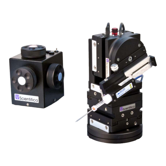
1.2.3 Product Walkthrough Figure A: PatchStar micromanipulator, with key components indicated Rotary Base Y Axis (green adjuster) X Axis (blue adjuster) Z Axis L-bracket Z Axis (red adjuster) Dovetail strip (Y Axis) Dovetail strip (X Axis) Dovetail strip (Z Axis) Rotary stage 1.2.4 Left and right handed configurations... -
Page 6: Packing List
The shipping department may wish to notify the carrier at this point. If the shipping carton is not damaged, carefully remove and identify all of the components as listed below. If any of items are missing, contact Scientifica Ltd. Please retain the packaging for storage or future transportation of the system. -
Page 7: Optional Items
Breakout box lead (25-way D-type) Screw kit (contents as per label inside lid) Hex key set Power Cable (cable provided will depend on your country) 1U rack mounted controller 1 per 1U rack Mains lead, locale specific 1 per 1U rack USB lead (A-type to B-type) Software CD Setup and Operation Manual... - Page 8 Control Cube PatchPad PatchPad Display PatchPad Touch Joystick...
- Page 9 Adaptive accessories Steep bracket (PS-7550) Shallow bracket (PS-7500) Flip-up bracket (PS-7700) Low profile bracket (PS-7800) Head stage plate (PS-7650) Dovetail probe holder (PH-1000)
-
Page 10: Initial Setup
Fixed Sliding Probe Carriage Universal Rod holder (PS-7750) (PS-7600) Electrode Holding Bar (EHB-500) 3.0 Initial Setup 3.1 Mechanical configuration of the PatchStar Please remember: adjustment or removal of any screws or components other than those noted in this manual can adversely affect the performance and operation of your micromanipulator and may invalidate your warranty. - Page 11 Figure B: The PatchStar, shown in left and right handed configurations 1. Loosen the dovetail screws on the lower part of the Z-axis L-bracket using a 3mm allen key. Do not remove these screws completely. Figure C: Left hand view, L-bracket dovetail screws indicated 2.
- Page 12 3. Loosen the dovetail screws on the X axis (blue) Figure E: Rear view, indicating X axis (blue) dovetail screws 4. Remove the X axis (blue) from the Y axis (green) (1), turn the X axis through 180º and slide it back onto the Y axis (2) so that the manual adjustment knob and cable are positioned on the left side of the assembly when seen from the front.
-
Page 13: Arranging The Patchstar In 'Low-Profile' Configuration
Slide Figure G: Left hand view, replacing top half of PatchStar 7. The head stage slide can now be set to project on the right side of the manipulator. Refer to section 3.2.3 for details. Note: You may need to reset the magnetic stops on the rotary base and vertical rotary stage, as described in section 3.2 To return a PatchStar from a left handed configuration back to right handed, follow the same steps outlined above. - Page 14 Figure I: Left hand view, L-bracket dovetail screws indicated 2. Slide the upper part of the manipulator off the X axis (blue). S lid e Figure J: Left hand view, Sliding the top section of the PatchStar 3. Loosen the dovetail screws on the upper part of the Z axis Bracket (1) and remove from the Z axis L-bracket (2).
-
Page 15: Mechanical Mounting And Positioning Of The Patchstar
Slide Figure L: Left hand view, fitting the Z axis (red) to the L-bracket 5. Slide the low profile bracket (1) onto the X axis (blue) and tighten the dovetail screws on the long edge of the low profile bracket (2) Slide Figure M: Fitting the Z-axis onto the lower half of the PatchStar 3.2 Mechanical mounting and positioning of the PatchStar... - Page 16 Slid e Figure N: PatchStar (left hand view), indicating rotary stage dovetail screws and removing the rotary base. 2. Ensure that the 2 set screws that fix the rotary stop ring are loose by turning them anti-clockwise, thus enabling the upper plate to rotate 360º. Tighten Loosen Figure O: Rotary base, with set screws indicated...
-
Page 17: Setting The Rotational Stops On The Rotary Base
5. In the reverse of step 1, slide the PatchStar assembly back onto the rotary base and tighten the 2 dovetail locking screws on the Y axis (green). 3.2.2 Setting the rotational stops on the rotary base The rotary base allows the PatchStar to be rotated between two magnetic stops 100° apart. The magnetic stops provide enough force to hold the PatchStar in place for the application but can be easily moved by hand between stops without having to undo any locking mechanism or use any tools. - Page 18 3. Tighten the grub screw and check you can rotate the Patchstar clockwise away from the experiment to the other stop. Note: The magnetic stops in the base are designed to be held in place by one of the two grub screws –...
-
Page 19: Setting The Rotational Stops On The Rotary Stage
3.2.3 Setting the rotational stops on the rotary stage The rotary stage ensures that an ideal sample approach angle can be achieved. The stage is rotated manually between two magnetic stops. The position of these stops can be adjusted to suit the application. 1. - Page 20 3a. For a left handed setup: Ensure that the rotary stage is positioned midway between the two stops and then loosen both of set screws using a 1.5 mm allen key. Rotate the front plate clockwise until the magnet which determines the approach angle is engaged with the stop.
-
Page 21: Attaching The Head Stage Assembly
3.2.4 Attaching the head stage assembly The headstage assembly is mounted to the front of the rotary stage. It can be mounted using either of the pairs of channels on the rotary stage (marked ‘a’ and ‘b’ below). Each channel contains four tapped holes, two of which should be used to secure the dovetail slide. -
Page 22: Exchanging Magnetic Base To Thumb Screw Lock
This can be ordered as a standard alone part from Scientifica (code PS-LBASE). If this part is ordered a new rotational base will be shipped with the thumbscrew lock preinstalled. In order to fit this onto the PatchStar remove the magnetic base form the manipulator by loosening the screws on the bottom most dovetail rail and sliding the manipulator off the base, as indicated in figure N. - Page 23 Figure X: loosen screw using 2.5mm allen key to remove and replace brass magnetic ‘stop’ for rubber variant. Once exchanged, the top of the rotational base can be replaced and securely tightened in place. Locate the brass ‘cup’ and insert it into the clamp block so that the flat edge fits flush against the inside edge of the block as indicated in figure Y.
- Page 24 Figure Z. Attach the clamp block onto the side of the PatchStar base using the screws provided onto the full height section of the base. Finally insert the thumb screw locking screw into the hole provided and tighten to clamp the base in the desired position.
-
Page 25: Electrical Setup Of The Patchstar
There is also an optional connection via USB for PC control using Linlab software. Ensure mains disconnect for external mains power supply outlet for the Scientifica Control Rack is accessible. There is no integrated mains disconnect located within the PatchStar unit. -
Page 26: Control Racks
3.3.1 Control Racks For connecting the PatchStar to the Control Rack and user interface please see the relevant Control Rack User Manual. 4.0 Powering up the system Once all positioning and cable connections are complete you are ready to switch on your PatchStar system. - Page 27 Compressed air can be used to remove dust from the top of the PatchStar. Care must be taken to prevent dust entering the vents during the process. • Never use fluid to clean the unit or allow fluid to enter the unit to prevent danger of electrocution.
-
Page 28: Frequently Asked Questions
6.0 Frequently Asked Questions 6.1 No Movement • Check Scientifica Control rack is properly connected according to the Control rack User Manual and that the rack is turned on. • Ensure all cables and devices are correctly and securely connected as per the relevant Control Rack User Manual and the rack is turned on. - Page 29 Are the stops on the rotary stage set correctly? • Magnetic Lock: When setting the approach angle, ensure the lower lock stop position of the vertical rotation lock is used. The magnetic lock should ensure that the sliding bracket doesn’t rotate downwards whilst freely standing. •...
- Page 30 • There should be a soft loop on all wires from the manipulator, ideally fixed to a point close to the manipulator mount. • The cables can also be fixed to the Faraday cage above the manipulator, but only if the Faraday cage is isolated from the floor. •...
-
Page 31: Specifications
7.0 Specifications Supply voltage range Supply frequency Power/current rating * indicates that this unit on its own is not functional and needs to be connected to a Control Rack for normal operation Number of axis 3 with virtual 4th axis Travel 20 mm 0.1μm... -
Page 32: Warranty, Technical Queries And Returns
Scientifica’s Service Stock. 3. As soon as Scientifica receives the equipment it will be assessed to establish if any repairs are necessary. If these repairs are outside the warranty then Scientifica will need an order to complete the repairs;... -
Page 33: About Scientifica
Parts will be charged at Scientifica standard list price. For any warranty queries please contact your local distributor or Scientifica Ltd directly. Tel: +44 (0) 1825 749933 E-mail: info@scientifica.uk.com... - Page 34 © Scientifica Ltd 1A Kingfisher Court, Brambleside, Bellbrook Industrial Estate, Uckfield, TN22 1QQ, United Kingdom Tel +44 (0) 1825 749 933 Fax +44 (0) 1825 749 934 info@scientifica.uk.com...
Need help?
Do you have a question about the PatchStar Micromanipulator and is the answer not in the manual?
Questions and answers