Advertisement
Quick Links
INSTALLATION INSTRUCTIONS
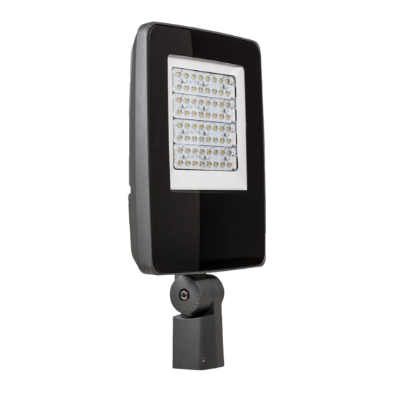
ClearScape LED
CSFS Small and CSFM Medium
This luminaire is intended for indoor or outdoor applications, ETL/cETL Listed to the UL 1598 standard, suitable for wet locations and IP66 rated
IMPORTANT:
Read carefully before installing. All work should be performed by a qualified Electrician. These
instructions may not provide directions to cover every variation and detail. To obtain additional
information, consult your vendor or contact the factory directly for assistance before attempting
Floodlight
anything with uncertainty. Improper installation and/or utilization may void manufacturer's
warranty.
This fixture must be grounded in accordance with local codes and the NATIONAL ELECTRIC
CODE. Failure to do so may result in serious personal injury. Luminaires should be operated on
grounded systems only.
Ungrounded power distribution systems may carry high transient voltages which can cause failure
of any type electrical equipment. Use of this equipment on ungrounded systems will VOID THE
WARRANTY.
GENERAL:
Upon receipt, inspect for any freight damage, which should be brought to the attention of the
delivering carrier. Compare the catalog description listed on the packing slip with the label on the
carton to assure you have received the correct material.
SF - Slip Fitter Mount
Note: Tenon must be 3.75" or longer.
© 2016 Philips Lighting Holding B.V. All rights reserved.
www.philips.com/luminaires
Part Number 443561208870 Rev. C
Page 1 of 4
Electrical Connection: (Not all options shown below are included.)
Connect the black fixture lead to the input voltage supply or Hot 1 (for
208/240V/480v wiring).
Connect the white fixture lead to the neutral supply or Hot 2 (for 208/240V/480v
wiring).
Connect the green or green/yellow ground lead to the incoming ground wire.
If Dimming is an option; connect the purple dimming positive lead to the supply
dimming positive lead.
If Dimming is an option; connect the grey dimming negative lead to the supply
dimming negative lead.
(2) Splice Cover Screws
Splice Cover Screws
STEP 1:
Remove (2) splice cover screws and splice cover. To access wire
splice area.
STEP 2:
Route the supply wire through the tenon. Secure the supply wire to
keep from sliding back down the pole. Route wire through slip fitter
arm into splice area.
STEP 3:
Holding routed wires in splice area, carefully lower luminaire onto
tenon. Check to insure that wires are not pinched between inside of
slip fitter and top of tenon and that luminaire and wires rotate freely.
.
Advertisement

Related Manuals for Philips ClearScape LED Series


Summary of Contents for Philips ClearScape LED Series
- Page 1 Check to insure that wires are not pinched between inside of slip fitter and top of tenon and that luminaire and wires rotate freely. © 2016 Philips Lighting Holding B.V. All rights reserved. www.philips.com/luminaires Part Number 443561208870 Rev. C...
- Page 2 Adjustment Bolt and loosened in Step 2 to 47 ft.-lbs. aiming indicator lines © 2016 Philips Lighting Holding B.V. All rights reserved. www.philips.com/luminaires Part Number 443561208870 Rev. C Page 2 of 4...
- Page 3 Step 2 to 75 ft.-lbs. Adjustment Bolt and aiming indicator lines © 2016 Philips Lighting Holding B.V. All rights reserved. www.philips.com/luminaires Part Number 443561208870 Rev. C Page 3 of 4...
- Page 4 STEP 3: After servicing luminaire, carefully rotate glass door frame up into closed position and retighten screws loosened in Step 1. © 2016 Philips Lighting Holding B.V. All rights reserved. Philips Lighting North America Philips Lighting Canada Ltd. www.philips.com/luminaires Corporation...