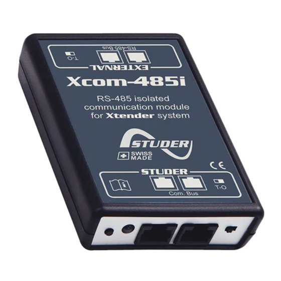
Summary of Contents for Studer Xcom-485i
- Page 1 Xcom-485i Isolated RS-485 communication module for Xtender and Vario-systems User Manual Studer Innotec SA 2019 – V1.0.0 4O9T...
-
Page 2: Table Of Contents
FUNCTIONALITIES OF THE XCOM-485I ................... 7 INSTALLATION OF THE XCOM-485I ....................7 Selection of functionality and pinout arrangement ............7 Cable between Xcom-485i and third party device ............8 Selection of the PIN assignment of the RS-485 bus connection ........8 Mounting ..........................8 Connection of the communication bus (Studer side) ............ -
Page 3: Introduction
The protocol used on the RS-485 side is Modbus RTU (see our website for more information). EGAL NOTICE The use of Studer Innotec SA devices is the responsibility of the customer in all cases. Studer Innotec SA reserves the right to make any modification to the product without prior notice. ONVENTIONS 1.2.1 Symbols... -
Page 4: Safety Precautions
Installation, commissioning, use and maintenance of this device cannot be supervised by the company Studer Innotec SA. For this reason, we do not accept any liability for damages, costs or losses generated either by an installation that is not conforming to the prescriptions, by a defective operation or by poor maintenance. -
Page 5: Eu Declaration Of Conformity
Studer Innotec SA Xcom-485i EU DECLARATION OF CONFORMITY The communication module Xcom-485i described in this manual meets the requirements specified in the following EU directives and standards: Low Voltage Directive (LVD) 2014/35/EU - EN 62368-1:2014/AC:2015 Electromagnetic Compliance (EMC) Directive 2014/30/EU... -
Page 6: Material Needed For The Installation
SD card with manual THER REQUIRED MATERIAL In addition to the material delivered with the communication set the use of an Xcom-485i necessitates a cross-headed screwdriver #1 (P1). Since the Xcom-485i is dedicated to communicate with a third-party system (SCADA, PLC etc.) you will need a specific cable crafted with the proper connector and pinning on each side. -
Page 7: Functionalities Of The Xcom-485I
Xcom-485i FUNCTIONALITIES OF THE XCOM-485I The Xcom-485i module offers the possibility to interact with a Studer Xtender/Vario system with a third-party device (SCADA system, PLC, etc.) using Modbus RTU on RS-485. The technical specification of this protocol is available on Studer's web site. This protocol will allow the third-party device to read and write data, get messages and fully control the Xtender/Vario system. -
Page 8: Cable Between Xcom-485I And Third Party Device
Jumper array OUNTING The Xcom-485i can be mounted directly on any support by means of the supplied fixing plate, on a smooth surface with double-side adhesive or on DIN rail using the DIN rail clips (part of the Xcom-485i communication set). - Page 9 Studer Innotec SA Xcom-485i User manual V1.0.0...
-
Page 10: Connection Of The Communication Bus (Studer Side)
ONNECTION OF THE COMMUNICATION BUS TUDER SIDE The Studer bus is daisy chained to the other XT/VT/VS Studer components and is powered by the communication plug as soon as the upfront device is powered. The Xcom-485i module should not be installed between 2 devices powered by the battery. Connect the Xcom-485i module with the supplied cable (2m). -
Page 11: Elements On The Studer Side Of The Module
It is explained in chapter 5.7.1. Studer device communication connectors These connectors allow the Xcom-485i to be connected with an Xtender system. This is the Studer communication side of the device. Do not connect any devices suited for standard Ethernet connection. - Page 12 T (terminated) position. If there are two cables connected on port e (Xcom-485i connected to two other devices) place the switch in position O (open).
-
Page 13: Software Updates
Studer Innotec SA Xcom-485i SOFTWARE UPDATES In case of requirement of software upgrade of the system through the RCC unit, the Xcom-485i is automatically upgraded. The software updates are available in the download area of the website www.studer-innotec.com/en/downloads/. PDATING PROCESS Turn off all inverter units before making the update. -
Page 14: Dimensions
Studer Innotec SA Xcom-485i DIMENSIONS V1.0.0 User manual... - Page 15 Studer Innotec SA Rue des Casernes 57 1950 Sion – Switzerland Tel: +41(0) 27 205 60 80 Fax: +41(0) 27 205 60 88 info@studer-innotec.com www.studer-innotec.com...


Need help?
Do you have a question about the Xcom-485i and is the answer not in the manual?
Questions and answers