Table of Contents
Advertisement
Quick Links
Advertisement
Table of Contents

Subscribe to Our Youtube Channel
Summary of Contents for BMPRO MiniBoostPRO
- Page 1 OWNER’S MANUAL MiniBoostPRO TEAMBMPRO.COM...
- Page 3 To learn more about the BMPRO range of products, please visit our website teambmpro.com TEAM BMPRO...
-
Page 5: Safety Precautions
WARNING Correct installation is the most critical factor in ensuring the safe use of the MiniBoostPRO. If every consideration of these instructions has been satisfied, the MiniBoostPRO will be safe to operate. - Page 6 Designed by BMPRO, one of Australia’s leading power solution experts, the BMPRO range of MANUAL PART 032207 products are proudly Australian-Made in Melbourne, Victoria and represent a high-quality REV 1.0 product that will provide years of service. DISCLAIMER: BMPRO accepts no liability for any loss or damage which may occur from the improper or unsafe use of its products.
-
Page 7: Table Of Contents
CONTENTS SAFETY PRECAUTIONS ABOUT THE MINIBOOSTPRO What’s Included Additional Accessories Required for Installation Compatible Battery Types DESCRIPTION OF PARTS INSTALLATION INSTRUCTIONS Personnel Orientation, Ventilation and Thermal Considerations Mounting WIRING INSTRUCTIONS Cable Size Wiring and Connections Fusing Ignition Detect Battery Chemistry Selection... -
Page 8: About The Miniboostpro
MiniBoostPRO: 9 3x 40A Automotive Fuse 9 2x 2A Automotive Fuse COMPATIBLE BATTERY TYPES The MiniBoostPRO may be used to charge 12V batteries with capacities of 50-300AH and of the following chemistries: AGM/Wet, Gel and LiFePO4 (Lithium). -
Page 9: Compatible Battery Types
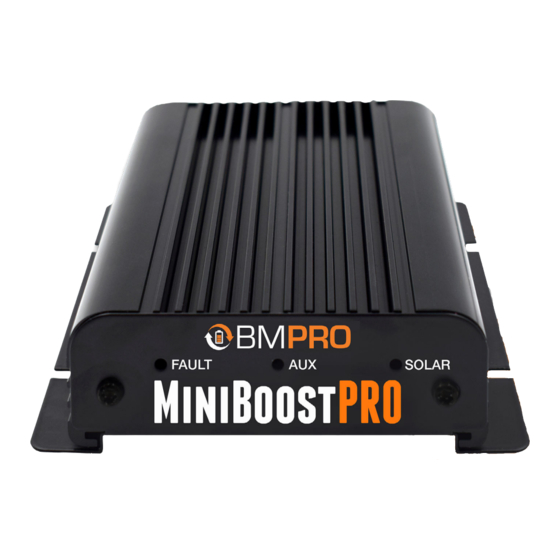
WARNING Do not connect other types of Lithium batteries to the MiniBoostPRO. DESCRIPTION OF PARTS Figure 1: MiniBoostPRO 1. Aux LED 6. Batt Out Primary charging source. Red cable to connect to the positive terminal of the battery to be charged 2. -
Page 10: Installation Instructions
MiniBoostPRO, install the unit in a well-ventilated area that allows for continuous airflow around the unit. Overheating of the MiniBoostPRO will affect the optimal operation of the unit. The MiniBoostPRO should not be mounted in the engine bay. It is not designed for engine bay applications. MOUNTING Securely mount the MiniBoostPRO to any suitably strong flat surface. -
Page 11: Wiring Instructions
System such as the BatteryPlus35 or J35. If using a Power Management System, connect the MiniBoostPRO’s Batt Out and Common Negative cables to the positive and negative primary input. The MiniBoostPRO may be wired direct to the secondary battery via a protective fuse. - Page 12 FOR STANDARD INSTALLATION...
- Page 13 FOR INSTALLATION WITH BP35...
- Page 14 FOR INSTALLATION WITH J35...
-
Page 15: Fusing
Users must place the fuse as close as possible to the battery. WARNING Fuse protection is required even if no BMPRO battery management system is installed. IGNITION DETECT The MiniBoostPRO is equipped with an ignition detect cable, which is designed to prevent your primary battery from excessive discharge and detects when the vehicle alternator is turned on. - Page 16 BATTERY CHEMISTRY SELECTION The MiniBoostPRO’s green battery chemistry cable is used to select the battery chemistry (Figure 5,6,7). Setting the correct battery chemistry ensures that the appropriate voltage levels are set for charging (Table 3). Selecting 12V Gel Battery When using the...
-
Page 17: Battery Charging
Battery Positive Terminal Table 3: Battery Chemistry Voltage Levels BATTERY CHARGING The MiniBoostPRO features a multi-stage charging profile to charge your secondary battery. These stages are boost/blending/boost charge and solar /bypass/ blending bypass. This enables the charge to deliver the maximum current, until the terminal voltage has risen to the battery’s preset level (see... -
Page 18: Absorption
ABSORPTION Absorption ensures that the MiniBoostPRO's battery’s voltage is kept at its preset level. During this stage, the current is gradually reduced to less than 2A for 2 minutes. This allows the battery to absorb more power. FLOAT Float is the final stage of the battery charging profile. This keeps the... -
Page 19: Protective Features
PROTECTIVE FEATURES The MiniBoostPRO has the following built in protection features: Spark Free Protection If the MiniBoostPRO is not connected to an input source, the unit provides prevention of sparking in the case of accidental short circuit on the output side. -
Page 20: Fault Codes
FAULT CODES If there is a fault with the MiniBoostPRO set-up that prevents the battery from charging, the red fault LED will illuminate and flash a code to describe the fault (Table 5). RED FLASHING FAULT SOLUTION SEQUENCE No source and... -
Page 21: Servicing And Cleaning
FAQS 1. Can I use the MiniBoostPRO inside my engine bay? The MiniBoostPRO cannot be used inside an engine bay as it is rated to IP20. 2. Does the MiniBoostPRO connect to home solar panels? No, the MiniBoostPRO will not connect if the voltage rating of your home solar panels is over 25V. -
Page 22: Troubleshooting
TROUBLESHOOTING If you need help to troubleshoot your MiniBoostPRO, contact our customer service team online at teambmpro.com/technical-support/ or give us a call on (03) 9763 0962. SPECIFICATIONS MINIBOOSTPRO SPECIFICATIONS Auxiliary input voltage 9-15V DC Solar input voltage 9-25V DC Gel: 14.2V Output Voltage AGM/Wet: 14.4V... -
Page 23: Warranty Terms And Conditions
7. BMPRO will not be liable for any costs, charges or expenses incurred in the process of returning a product in order to initiate a warranty claim... - Page 24 BMPRO TEAM +61 3 9763 0962 sales@teambmpro.com BMPRO 19 Henderson Rd, Knoxfield VIC 3180 Australia .COM teambmpro.com...


Need help?
Do you have a question about the MiniBoostPRO and is the answer not in the manual?
Questions and answers