
Subscribe to Our Youtube Channel
Related Manuals for Mueller ISOBUS SPRAYER-Controller MAXI 3.0


Summary of Contents for Mueller ISOBUS SPRAYER-Controller MAXI 3.0
- Page 1 Operating Instructions SPRAYER-Controller MAXI and MIDI 3.0 Version: V1.20170116 30303187-02-EN Read and follow these operating instructions. Keep these operating instructions in a safe place for later reference.
- Page 2 Document number: 30303187-02-EN As of software version: 7.5s Original language: German Copyright © Müller-Elektronik GmbH & Co.KG Franz-Kleine-Straße 18 33154 Salzkotten Germany Phone: ++49 (0) 5258 / 9834 - 0 Fax: ++49 (0) 5258 / 9834 - 90 Email: info@mueller-elektronik.de Homepage: http://www.mueller-elektronik.de...
-
Page 3: Table Of Contents
Table of contents Table of contents For your safety Basic safety instructions Layout and meaning of warnings Layout and meaning of alert messages User requirements Intended use Disposal Safety sign for the field sprayer Safety stickers on the product EG declaration of conformity About these Operating Instructions Target group of these Operating Instructions Applicability... - Page 4 Table of contents Control units Operating job computer on the field Tank filling 6.1.1 Filling up the tank manually without additional systems 6.1.2 Filling up the tank with TANK-Control 6.1.3 Filling up the tank with TANK-Control and fill stop Controlling the boom 6.2.1 Lifting and lowering the boom 6.2.2...
- Page 5 Table of contents 7.6.3 Configuring the reverse driving sensor 7.6.4 "Simulated speed" function Configuring sections 7.7.1 Entering the number of nozzles per section 7.7.2 Switching sections off permanently 7.7.3 Permanently switching off a section using a sensor 7.7.4 System delay when switching the sections Configuring the nozzles - for field sprayers with pressure sensor regulation 7.8.1 Nozzle assistant...
- Page 6 Table of contents Steering in automatic mode Steering in manual mode Steering the trailed implement against the slope 8.2.2 Preparing TRAIL-Control for road driving Locking TRAIL-Control 8.2.3 Driving in reverse Alarm messages History 10.1 V1.20170116 V1.20170116 30303187-02-EN...
-
Page 7: For Your Safety
For your safety Basic safety instructions For your safety Basic safety instructions Operation Be sure to always comply with the following instructions during operation: ▪ Before you leave the vehicle cab, ensure that all automatic mechanisms are deactivated or manual mode is activated. ▪... -
Page 8: Layout And Meaning Of Alert Messages
For your safety Layout and meaning of alert messages CAUTION This signal word identifies hazards that could potentially cause minor or moderate physical injury or damage to property, if not avoided. NOTICE This signal word identifies hazards that could potentially cause damage to property, if not avoided. There are some actions that need to be performed in several steps. -
Page 9: User Requirements
For your safety User requirements User requirements ▪ Learn to operate the product in accordance with the instructions. Nobody must operate the product before reading these Operating Instructions. ▪ Please read and carefully observe all safety instructions and warnings contained in these Operating Instructions and in the manuals of any connected vehicles and farm equipment. -
Page 10: Safety Stickers On The Product
For your safety Safety stickers on the product Safety sign Where to attach Meaning Near the the bend area between tractor Do not stay in the bend area and trailed implement. during operation. Safety stickers on the product Safety sticker on the product Do not clean with a high-pressure cleaner. -
Page 11: About These Operating Instructions
About these Operating Instructions Target group of these Operating Instructions About these Operating Instructions Target group of these Operating Instructions The document is intended for operators of field sprayers that are equipped with the SPRAYER- Controller MAXI 3.0 system with the standard configuration. The manual will show you: ▪... -
Page 12: Layout Of References
About these Operating Instructions Layout of references Type of depiction Meaning ⇨ Result of the action. This will happen when you perform an action. ⇨ Result of an operating instruction. This will happen when you have completed all steps. Requirements. In the event that any requirements have been specified, these must be met before an action can be performed. -
Page 13: Product Description
Product description Rating plate Product description Rating plate Abbreviations on the rating plate Abbreviation Meaning Customer number If the product was manufactured for an agricultural machinery manufacturer, the agricultural machinery manufacturer's item number will be shown here. Hardware version Müller-Elektronik item number Operating voltage The product may only be connected to voltages within this range. -
Page 14: Mounting And Installation
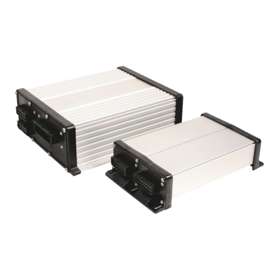
Mounting and installation System Overview Mounting and installation System Overview Depending on which job computer is used as the base computer for the main system, and which additional components are installed, the overall system can have different sizes. Example: MAXI 3.0 as the main job computer V1.20170116 30303187-02-EN... -
Page 15: Main System - Maxi
Mounting and installation System Overview Example: MIDI 3.0 as the main job computer 4.1.1 Main system - MAXI The system can be expanded. In the basic version, it consists of a job computer that is connected to the junction box and the ISOBUS power socket of the tractor. 30303187-02-EN V1.20170116... -
Page 16: Main System - Midi
Mounting and installation System Overview Main system - Version MAXI 3.0 ISOBUS job computer SPRAYER-Controller 30303187 MAXI 3.0 Connector cable for job computer to ISOBUS Cable length - Item number: Connection to ISOBUS power socket 1m - 3030314301 2.5m - 3030314601 4m - 3030314401 5.5m - 3030314801 6.5m - 3030314001... - Page 17 Mounting and installation System Overview Main system of the MIDI 3.0 version Connector cable for job computer to ISOBUS Cable length - Item number: Connection to ISOBUS power socket 1m - 3030314301 6.5m - 3030314001 2.5m - 3030314601 8.5m - 3030314201 4m - 3030314401 11m - 3030314101 5.5m - 3030314801...
-
Page 18: Extension: Distance-Control Ii
Mounting and installation System Overview 4.1.3 Extension: DISTANCE-Control II DISTANCE-Control II Connection to ECU MAXI 3.0 or to the last Cable length - Item number: ECU MIDI. 0.3m - 30322355 10m - 30322356 6.5m - 30322357 3.2m - 30322358 1.5m - 30322359 Termination plug. -
Page 19: Extension: Tank-Control Ii
Mounting and installation System Overview 4.1.4 Extension: TANK-Control II TANK-Control II Connection to the main system or to a system Cable length - Item number: add-on, with the option of connecting further 1m - 3030308901 add-ons. Connection to the main system or to a system 1m - 30303089 add-on TANK-Control II - Operating device and... -
Page 20: Instructions For Safe Installation
Mounting and installation Instructions for safe installation Connection to the main system or to a system Cable length - Item number: add-on 0.3m - 30322355 1.5m - 30322359 3.2m - 30322358 6.5m - 30322357 10m - 30322356 EDS communication module Connection to the EDS bus EDS modules Termination plug... - Page 21 Mounting and installation Connecting the job computer to the ISOBUS 5. Screw the dust protection cap of the connector and the socket together. ⇨ 6. When the work is completed, separate the connection and screw the dust protection cap back ⇨...
-
Page 22: Basic Control Principles
Basic control principles Switching job computer on and off Basic control principles Switching job computer on and off Procedure You can switch on the job computer as follows: 1. Provide job computer with power. The possibilities for this are as follows: For ISOBUS tractors: Switch on the tractor with the ignition key. -
Page 23: Screen Structure
Basic control principles Screen structure Icon for the application in the selection menu of the TOUCH800 terminal Screen structure 5.4.1 Work screen The work screen is always shown during work and informs you of the status of the field sprayer. The work screen is divided into several areas. -
Page 24: Spray Data Area
Basic control principles Screen structure Function icon Function Opens the "Boom Folding" screen. Switches between manual and automatic regulation of the application rate. Opens a screen with additional functions. Starts and stops the drawbar steering (or stub axle steering). Switches between two levels of icons. Shows the next page with function icons. - Page 25 Basic control principles Screen structure Icon Meaning See: Using Automatic mode [➙ 42] The application rate will be manually regulated. See: Changing the application rate in manual mode [➙ 42] The bar graph only appears when the target rate is changed in automatic mode using the +10% and -10% buttons.
-
Page 26: Boom Display Area
Basic control principles Screen structure 5.4.3 Boom display area In the boom display you find the following information: ▪ Number of sections ▪ Which sections are preselected or switched off ▪ Which sections are applying Illustration The diagrams below show how the sections may appear in the boom display area: Sections 1 and 2 are closed and deactivated. -
Page 27: Icons Beside The Implement Image
Basic control principles Screen structure Picture Status of the section valve Status of the control/main valve The section is permanently deactivated When the sections are automatically switched using SECTION-Control, you have to ensure that the sections are not deactivated using an S-Box or a joystick. In this case, the section would be marked with a red cross and remain closed. - Page 28 Basic control principles Screen structure Icon Meaning Stirrer has been stopped. Cause: Stopped by the driver. (not flashing) Stirrer is working. Fresh water tank is being emptied. Low-pressure cleaner is being used. The ring line is being rinsed. Working lights are on. Nozzles used in Vario mode.
-
Page 29: Icons On The Implement Image
Basic control principles Screen structure Icon Meaning Air compressor is off. Air compressor is on. Manual mode is activated. The number indicates the drop size. Drop size (automatic mode activated). Page 2 - Counters and sensors Icon Meaning Wind strength Output in litres per minute Area output per hour 5.4.5... -
Page 30: Control Units
Basic control principles Control units TRAIL-Control Meaning Icons for drawbar steering Icons for axle steering No TRAIL-Control or TRAIL- Control in automatic mode. TRAIL-Control is installed but is deactivated. TRAIL-Control is in manual mode. The drawbar is locked with a The implement is steered to the left. -
Page 31: Operating Job Computer On The Field
Operating job computer on the field Tank filling Operating job computer on the field Tank filling After each fill-up of the spray liquid tank, you can enter how much water you added. Methods Depending on what additional equipment is fitted to your field sprayer, the process may be different. In this you can: ▪... -
Page 32: Filling Up The Tank Manually Without Additional Systems
Operating job computer on the field Tank filling 6.1.1 Filling up the tank manually without additional systems If you fill up the spray liquid container manually without any additional systems, you need to enter the new tank content manually on the terminal. Function icon Function Tank was fully filled up. -
Page 33: Filling Up The Tank With Tank-Control And Fill Stop
Operating job computer on the field Tank filling 6.1.3 Filling up the tank with TANK-Control and fill stop If a TANK-Control with fill stop has been installed and configured on the field sprayer, you can use it. It will stop tank filling automatically when a specified fill level is reached. You can define up to two refill limits for tank filling. -
Page 34: Controlling The Boom
Operating job computer on the field Controlling the boom - Open the ball valve. ⇨ The icon will appear. ⇨ Filling starts. ⇨ When the fill level defined as refilling limit 1 is reached, the ball valve closes and filling is terminated. -
Page 35: Locking The Boom
Operating job computer on the field Controlling the boom Boom is being lifted - the arrow in the middle shows the direction "MANU" means that DISTANCE-Control is deactivated and the boom must be raised and lowered manually. 6.2.2 Locking the boom This function makes it possible to lock the boom so it remains stable when the weight is unbalanced. - Page 36 Operating job computer on the field Controlling the boom Structure of a boom The following diagram shows the structure of booms and what the individual boom parts are called. The diagram shows a field sprayer with a seven-part boom, but it also applies to smaller booms. Parts of the boom on a field sprayer Three-part boom Boom part: Inner left...
-
Page 37: Raising And Lowering The Boom Sides (Tilting Up / Down)
Operating job computer on the field Controlling the boom Function icons On the following diagram, you see how a seven-part boom is shown on the function icons. Directional arrow Arrow pointing inwards means: Fold in Arrow pointing outwards means: Fold out Sections of the boom marked in grey are not folded in or out with this function icon Sections of the boom marked in white are folded in or out with this function icon Use the following function keys to operate the function:... -
Page 38: Sloping The Boom
Operating job computer on the field Controlling the boom Function icon Function Lowers the right boom side. Lowers the left boom side. Raises both boom sides symmetrically. Lowers both boom sides symmetrically. Procedure 1. Press the function key with the desired function. ⇨... - Page 39 Operating job computer on the field Controlling the boom When turning on a slope, you can press a button to slope the boom in the opposite direction. Use the following function keys to operate the function: Function icon Meaning Activates the function. Each time the button is pressed, the target position of the boom (white arrows) changes.
-
Page 40: Starting Application
Operating job computer on the field Starting application You have calibrated the boom potentiometer (slope angle sensor). [➙ 82] Procedure 1. Drive across the slope gradient with the field sprayer. 2. Position the boom parallel to the sloped ground. –... -
Page 41: Regulating The Application Rate
Operating job computer on the field Regulating the application rate ⇨ As soon as the minimum speed is exceeded, the field sprayer starts the application. Spray cones appear under the boom icon: ⇨ You have started application. Immediate application There may be situations where you want to start spraying while the sprayer is still at a standstill. For example, when you have stopped on the field. -
Page 42: Changing The Application Rate In Manual Mode
Operating job computer on the field Regulating the application rate 6.4.1 Changing the application rate in manual mode When the field sprayer is in manual mode, the application is not regulated according to a specified rate. The application rate must be set manually instead. The application rate must be regulated manually when the following icon appears in the spray data area of the work screen: Application in manual mode... -
Page 43: Setting The Target Rate
Operating job computer on the field Regulating the application rate ▪ Working width is set. ▪ The speed of the field sprayer is higher than the speed for the "Regulation off below" parameter. ▪ The parameter "Regul. factor" has been set. Mode of operation In the following cases, the flow is automatically adjusted: ▪... -
Page 44: Stopping Application
Operating job computer on the field Operating sections – from tasks, – from prescription maps, – from external sensors. Illustration Target rate from parameters Target rate from an external source Target rates from external data sources have a higher priority than the target rate entered in the job computer. -
Page 45: Treating Weed Infestations
Operating job computer on the field Treating weed infestations Treating weed infestations "Localized mode" is designed for the targeted treatment of small weed infestations. In contrast to normal mode, in localized mode you can switch individual sections on and off, even if they are not adjacent to one another. -
Page 46: Operating The Me Joystick
Operating job computer on the field Operating the ME joystick Function icon Function Resets the "Work time" counter. Pressed briefly: Continue to the total counters Pressed long: Back to the work screen Clears the contents of the displayed trip counter. Stops the trip counter. -
Page 47: Preview Mode For The Me Joystick
Operating job computer on the field Operating the ME joystick 1. Move the side switch into the desired position and hold. ⇨ The LED on the ME joystick lights up in the corresponding colour. 2. Press button with the desired function. ⇨... -
Page 48: Using Foam Markers
Operating job computer on the field Using foam markers ⇨ The button assignment appears: - Press to view the assignment on each level. 4. You can also activate the Preview mode [➙ 47]. Using foam markers Foam markers produce foam that can be applied by the field sprayer driver on the field at the ends of the boom. -
Page 49: Regulating The Drop Size With Airtec
Operating job computer on the field Regulating the drop size with AIRTEC Additional functions Function icon Function that can be activated or deactivated Working lights 1 and 2 Beacon Ring line circulation Cleaning the ring line circulation Tank interior cleaning Spray agent pump Stirrer Low-pressure cleaner... - Page 50 Operating job computer on the field Regulating the drop size with AIRTEC Preconditions Minimum equipment of the field sprayer: ▪ Nozzles with air support ▪ Air compressor: on the field sprayer or on the tractor. Mode of operation The job computer regulates the air pressure such that the drop size always remains constant. Even when the spray pressure changes.
-
Page 51: Switching The Air Compressor On And Off
Operating job computer on the field Regulating the drop size with AIRTEC Function icon Meaning Reduces the pressure. Calls up the screen with settings. Smaller nozzle. Bigger nozzle. 6.11.1 Switching the air compressor on and off The system works with two types of compressors: ▪... -
Page 52: Airtec In Manual Mode
Operating job computer on the field Regulating the drop size with AIRTEC - Set the drop size. ⇨ The set drop size appears on the work screen. 6.11.3 AIRTEC in manual mode In manual mode, you control the air pressure manually. The air pressure changes the drop size. Procedure - Set the air pressure. -
Page 53: Configuring The Job Computer
Configuring the job computer Configuring the control units Configuring the job computer Configuring the control units The joystick and S-Box control units are configured on a screen. ▪ "Joystick" parameter: – "Without Joystick": Joystick is not connected. All functions will be controlled using the terminal or an ME S-Box. -
Page 54: Entering Field Sprayer Parameters
Configuring the job computer Entering field sprayer parameters You have to configure the following Section with more information Collaboration with the terminal Configuring the communication with the terminal (Condensed Work State) [➙ 57] Calibrating the flow meter [➙ 58] Calibrating the flow meter Selecting and configuring the speed sensor [➙... - Page 55 Configuring the job computer Entering field sprayer parameters Wheel pulses Number of pulses the wheel sensor sends to the job computer on a 100m distance. Used to calculate the speed. The number is determined by the wheel sensor calibration. Regulation factor In Automatic mode, the spray pressure will be adapted to the current speed of the field sprayer.
- Page 56 Configuring the job computer Entering field sprayer parameters Maximum wind speed Maximale Windgeschwindigkeit Wind sensor must be installed. If the maximum wind speed is exceeded, an alarm will be triggered. Tank size Size of the tank for the spray liquid. Tank level alarm When the volume of spray mixture in the tank falls below this value, an alarm message appears on the screen.
-
Page 57: Configuring The Communication With The Terminal (Condensed Work State)
Configuring the job computer Configuring the communication with the terminal (Condensed Work State) Configuring the communication with the terminal (Condensed Work State) The job computer allows you to configure the compatibility with various ISOBUS terminals. This is necessary, for example, when the ISOBUS standard changes with time, but a terminal cannot be updated. -
Page 58: Calibrating The Flow Meter
Configuring the job computer Calibrating the flow meter ▪ Nozzle: DET "Unit" - Value for terminals that consider the EDS nozzles as section subunits. To see whether the parameter is properly set: ▪ In Section Control, the number of displayed sections corresponds to the number of nozzles. Or there is another indication that the proper number of nozzles has been transmitted. - Page 59 Configuring the job computer Calibrating the flow meter WARNING Spray liquid or spray liquid residues Danger of poisoning or chemical burning ◦ Clean the spray liquid tank thoroughly prior to calibration. The field sprayer must be free of spray liquids or spray liquid residues. ◦...
-
Page 60: Calibrating The Flow Meter With The Nozzle Method
Configuring the job computer Calibrating the flow meter ⇨ The following screen appears: - Start application. ⇨ During application, the number of pulses will be counted on the "CALIBRATION – Main flow meter" screen. 6. Apply a few hundred litres. Do not fully empty the tank. This prevents air bubbles from forming and distorting the results. - Page 61 Configuring the job computer Calibrating the flow meter WARNING Spray liquid or spray liquid residues Danger of poisoning or chemical burning ◦ Clean the spray liquid tank thoroughly prior to calibration. The field sprayer must be free of spray liquids or spray liquid residues. ◦...
-
Page 62: Manually Entering The Number Of Pulses Per Liter For The Flow Meter
Configuring the job computer Selecting and configuring the speed sensor ⇨ The current flow appears on the "Measured flow" line. - Start application. 5. Go to one of the nozzles and carefully collect the water sprayed for 60 seconds by using the prepared measuring cup. -
Page 63: Calibrating The Speed Sensor Using The 100M Method
Configuring the job computer Selecting and configuring the speed sensor – Configuration: For systems without the option of selecting the sensor input, the "impulses per 100 metres" parameter must be set to 0. ▪ "Auto" – As of software V7.5, some systems enable automatic detection of the speed source. –... -
Page 64: Configuring The Reverse Driving Sensor
Configuring the job computer Selecting and configuring the speed sensor ⇨ The following function icons appear: - Stop calibration. - Abort calibration. 4. Drive the previously measured 100m distance and stop at the end. ⇨ During the drive, the currently determined pulses are displayed. - Stop calibration. -
Page 65: Configuring Sections
Configuring the job computer Configuring sections Procedure 1. Switch to the "SPEED" screen: > - Activate the simulated speed. By pressing again, you can deactivate the function. ⇨ The "Simulated speed" line appears. 3. Enter the speed to be simulated on the "Simulated speed" line. - Exit screen. -
Page 66: Permanently Switching Off A Section Using A Sensor
Configuring the job computer Configuring sections Permanently switched off sections are marked in white on the work screen Procedure 1. Switch to the "BOOM" screen: > ⇨ The "BOOM" screen appears. - Press. ⇨ The "SECTIONS" screen appears. ⇨ For each section, you can see one of the following icons: - Section activated - Section deactivated. -
Page 67: Configuring The Nozzles - For Field Sprayers With Pressure Sensor Regulation
Configuring the job computer Configuring the nozzles - for field sprayers with pressure sensor regulation 1. Read the operating instructions for the TRACK-Leader app to find out how to determine the delay times. 2. Determine the delay times. 3. Open the job computer application. 4. - Page 68 Configuring the job computer Configuring the nozzles - for field sprayers with pressure sensor regulation Determination of the fitting nozzles Selected nozzle Here, you can enter: - The intended application rate This is adopted directly from the "Rate" parameter. - The optimal pressure for the nozzle Here, you can see the speed at which this application rate can be reached.
-
Page 69: Calibrate The Nozzles
Configuring the job computer Configuring the nozzles - for field sprayers with pressure sensor regulation 4. In the "Results" area, you can see the speed at which the application rate can be achieved. 7.8.2 Calibrate the nozzles Illustration "Calibration" screen Selected nozzle Nozzle output at 3 bar - Result of the calibration... -
Page 70: Extremity Nozzles
Configuring the job computer Extremity nozzles 5. Calculate average application rate. - Stop application. - Activate automatic mode. 8. Switch to the "Calibration" screen: > > 9. On the "Nozzle" line – select nozzle for calibration. Standard nozzles are referred to by their colours. -
Page 71: Configuring The Extremity Nozzles
Configuring the job computer Extremity nozzles 7.9.1 Configuring the extremity nozzles Screen for configuring the extremity nozzles "Extremity nozzles set" parameter Currently selected extremity nozzle pair Extremity nozzles left and right Installation site for the left and right extremity nozzle "Extremity nozzles set"... -
Page 72: Operating The Extremity Nozzles
Configuring the job computer Extremity nozzles ⇨ The following screen appears: 2. On the "Extremity nozzles set" line, enter the set of extremity nozzles for which you want to enter settings. For example "2": ⇨ The saved settings appear on the screen. 3. -
Page 73: Vario And Select Mode - Configuring Multiple Nozzle Holders
Configuring the job computer Vario and Select mode - configuring multiple nozzle holders Function icon Meaning Activate and deactivate corner nozzles on left and right Activate and deactivate wide area nozzles on left and right Procedure To operate the extremity nozzles: 1. -
Page 74: Before You Buy Nozzles - Check The Possible Application Rates
Configuring the job computer Vario and Select mode - configuring multiple nozzle holders Function icon Function Serves to exclude nozzles 1-4 from the Vario mode. Activates the nozzle properties. Enables the calculation of possible application rates and working speeds. Changes the view between the application rate calculation and the working speed calculation. - Page 75 Configuring the job computer Vario and Select mode - configuring multiple nozzle holders 6. Only install nozzles that have been successfully tested by the job computer and for which there have been no error messages during the configuration. Possible nozzle ranges for nozzles are red and grey, in the pressure range from 2 bar to 6 bar Here, you can see the nozzle combination for Bar with the desired application rate.
-
Page 76: Vario Mode - Automatic Nozzle Selection
Configuring the job computer Vario and Select mode - configuring multiple nozzle holders 7.10.2 Vario mode - Automatic nozzle selection In Vario mode, the system automatically activates one or several of the installed nozzles to achieve the defined drop size. "MULTI NOZZLES"... -
Page 77: Select Mode - Manual Nozzle Selection
Configuring the job computer Vario and Select mode - configuring multiple nozzle holders Nozzle status on the work screen Orange nozzle is not applying. Green nozzle is applying. Nozzle excluded from Vario mode No nozzle mounted on carrier no. 4. Desired drop size Procedure To activate Vario mode:... -
Page 78: Configuring The Nozzles On The Multiple Nozzle Holder
Configuring the job computer Vario and Select mode - configuring multiple nozzle holders ⇨ The Select mode will be terminated as soon as you activate Vario mode or deactivate the nozzles manually. 7.10.4 Configuring the nozzles on the multiple nozzle holder You can individually configure each nozzle on the multiple nozzle holder. -
Page 79: Calibrate The Nozzles
Configuring the job computer Vario and Select mode - configuring multiple nozzle holders Nozzle color in accordance ISO identifier Output in l/min. at 3 bar with ISO 10625 Nozzle D Specific Procedure The "MULTI NOZZLES" screen is called up. 1. -
Page 80: Deactivating Nozzles
Configuring the job computer Vario and Select mode - configuring multiple nozzle holders 7.10.6 Deactivating nozzles You can only deactivate nozzles on a quadruple nozzle holder. The following options are available to you: ▪ You can deactivate a nozzle globally. ▪... -
Page 81: Configuring Airtec
Configuring the job computer Configuring AIRTEC 5. Enter the password. 6. Restart the job computer. 7.11 Configuring AIRTEC For the AIRTEC configuration, you only have to select the nozzle number for the mounted nozzle. NOTICE Wrong nozzle number Damage to the plants ◦... -
Page 82: Calibrating The Sensors For Reproducing The Boom Slope
Configuring the job computer Calibrating the sensors for reproducing the boom slope 2. Select the field sprayer type in the topmost box. ⇨ A diagram of the sprayer appears. 3. Measure the distances shown in the figure. 4. Enter the distances measured. 7.13 Calibrating the sensors for reproducing the boom slope The purpose of the calibration process is to detect and save the boom position at maximum slope... -
Page 83: Field Sprayer With Two Circulations And Job Computers
Configuring the job computer Field sprayer with two circulations and job computers 7.14 Field sprayer with two circulations and job computers For field sprayers with two manifolds and booms, which are controlled by two job computers, you must configure each job computer for the equipment of the respective boom. There are also the following settings: ▪... -
Page 84: Identifying The Job Computer
Configuring the job computer Field sprayer with two circulations and job computers Field sprayer with one boom at the front and one at the rear. Main system Auxiliary system 7.14.1 Identifying the job computer For systems with two ISOBUS job computers, you must identify both job computers. You must activate the so-called second connector on the main job computer. -
Page 85: Geometry On A Field Sprayer With Two Job Computers
Configuring the job computer Field sprayer with two circulations and job computers - Press. 4. Enter the service password: You can obtain the service password from your Müller-Elektronik contact person. - Call up the "ISO 11783 " screen. 6. Configure parameter. 7.14.2 Geometry on a field sprayer with two job computers You must measure and enter the following distances:... -
Page 86: Configuring The Units
Configuring the job computer Configuring the units ⇨ The following screen appears: ⇨ The red dot CRP_2 marks the first boom. 2. On the line above the drawing, select whether the second boom is located in front of or behind the first boom (looking in the direction of travel): "2nd boom, behind the 1st"... -
Page 87: Trail-Control
TRAIL-Control Configuring TRAIL-Control TRAIL-Control The TRAIL-Control system steers a trailer in such a way that its tires follow the tractor's track precisely. Available functions TRAIL-Control has the following functions: ▪ Steering for a trailed implement: – Drawbar steering – the drawbar of the trailed implement is steered in a selected direction. –... - Page 88 TRAIL-Control Configuring TRAIL-Control Function icon for Function icon for Meaning drawbar steering axle steering Steers the implement to the right. Centers the implement. Calls up the screens with settings. Activates the slope counter-steering function. Calls up the "CALIBRATION" screen. Starts the calibration of the middle position. Starts the calibration of the left limit stop.
-
Page 89: Calibrating Trail-Control
TRAIL-Control Configuring TRAIL-Control Hydraulic flow gain Enter only for implements with a proportional valve. Hydraulic flow is a value for setting the steering speed. Normally the value is between: 1.5%/° and 3%/° Deviation tolerance The deviation tolerance influences the behaviour of steering in the central position area. The lower the tolerance is set, the more sensitive the control reacts to small changes. -
Page 90: Teaching-In The Central Position And Limit Stops
TRAIL-Control Configuring TRAIL-Control In this step, the trailed implement is automatically steered to both sides and the voltages are measured. The calibration runs automatically. Teaching-in the central position and limit stops The appearance of the screens during calibration depends upon whether your trailed implement is steered via drawbar or stub axle. -
Page 91: Calibrating The Hydraulics Of The Proportional Valve
TRAIL-Control Configuring TRAIL-Control Phase 2: Recording the limit stops - Steer the trailed implement fully to the left. - Start the calibration. ⇨ The following message appears: "Most left position: Calibration is ready" - Confirm within 3 seconds. The time will be counted by a red clock: ⇨... -
Page 92: Configuring The Automatic Centering
TRAIL-Control Configuring TRAIL-Control Ground is not sloped. Slope sensor must not recognize any slope. Otherwise the "Slope counter- steering" function will not work properly. You have enough space to drive straight ahead for about 30 seconds. 1. Switch to the "CALIBRATION" screen: >... -
Page 93: Centering When Exceeding The Maximum Speed
TRAIL-Control Configuring TRAIL-Control - Press briefly. ⇨ The following screen appears: ⇨ An automatism is described on each line. On the left, you can see the conditions under which a mechanism is executed. On the right, the effects. 3. To activate functions, set the check mark on the desired line. These functions will be explained in the following sections. -
Page 94: Centering When Tapping The Centering Icon
TRAIL-Control Configuring TRAIL-Control For activation, mark the box near these icons. Centering when tapping the centering icon When you are working in automatic mode and tap the function icon, the system automatically centers the trailed implement. To do so, the system is switched to manual mode. In addition, you can define after how many seconds the automatic mode should be reactivated. -
Page 95: Reaction To The Reverse Driving Signal In Automatic Mode
TRAIL-Control Configuring TRAIL-Control Mode of operation As soon as the vehicle comes to a stop (speed = 0 km/h), the icon appears on the screen ( for axle steering). If you drive in reverse in the next 10 seconds, the trailed implement will be centered. If you only drive in reverse after the 10 seconds have expired, nothing happens. -
Page 96: Trail-Control - Using Drawbar And Stub Axle Steering
TRAIL-Control TRAIL-Control – Using drawbar and stub axle steering TRAIL-Control – Using drawbar and stub axle steering Work modes TRAIL-Control lets you work in two modes: ▪ in automatic mode ▪ in manual mode Function Function icon for drawbar Function icon for stub axle steering steering Switching TRAIL-Control on... -
Page 97: Steering The Trailed Implement
TRAIL-Control TRAIL-Control – Using drawbar and stub axle steering 8.2.1 Steering the trailed implement WARNING Danger of injury from trailed implement movement The trailed implement moves to the side during steering. This may cause danger for persons and materials in direct proximity to the trailed implement. ◦... - Page 98 TRAIL-Control TRAIL-Control – Using drawbar and stub axle steering Mode of operation When you activate the 'slope counter-steering' function, you can offset the track of the trailed implement to the left or right. The direction in which the track is offset depends on if the slope climbs or declines to the left or right of the implement.
-
Page 99: Preparing Trail-Control For Road Driving
TRAIL-Control TRAIL-Control – Using drawbar and stub axle steering - Activate or deactivate function: ⇨ On the screen, you can see whether the function is activated: - Function enabled - Function disabled. Using slope counter-steering in automatic mode When you work in automatic mode, the trailed implement is steered automatically. Procedure To steer against the slope in automatic mode: ... -
Page 100: Locking Trail-Control
TRAIL-Control TRAIL-Control – Using drawbar and stub axle steering WARNING Risk of accident through lateral movement of the trailed implement In road traffic, TRAIL-Control can lead the trailed implement to the side of the tractor track. This may cause a traffic accident. Before you drive on a road: ◦... - Page 101 TRAIL-Control TRAIL-Control – Using drawbar and stub axle steering ▪ You can configure the reaction for TRAIL-Control when a reverse driving signal is detected. To do so, read section: Configuring automatisms when driving in reverse [➙ 94] When a reverse driving signal is detected, a flashing icon always appears on the work screen. 30303187-02-EN V1.20170116...
-
Page 102: Alarm Messages
Alarm messages Alarm messages The following table lists possible error messages and a short help to remedy the fault. Axle suspension Text of alarm message Meaning Right axle height sensor is faulty. The angle sensor that measures the spring deflection for the right wheel is defective. - Page 103 Alarm messages Text of alarm message Meaning configured. Defective slope sensor. The signal voltage is outside of the valid range. Valid range: 0.5 V to 4.5 V The sensor is used both for DISTANCE-Control and for TRAIL-Control, and is therefore calibrated with each of these systems. BOOM The slope sensor installed on the boom of the field sprayer is defective or was not configured.
- Page 104 Alarm messages Text of alarm message Meaning No angle sensor signal. In the third calibration step, the angle sensor did not detect a change in the signal. Outlets are swapped. The hydraulic valves were connected wrong. Sensors are disturbed. Short signal interruption with all sensors BOOM Text of alarm message Meaning...
- Page 105 Alarm messages Text of alarm message Meaning The right ladder is not in transport position. Field mode is activated. Alarm appears when the "Tractor-ECU" job computer sends a signal that the mode was switched from driving on the road to driving on the field. When driving on the road, the joystick buttons will be ignored.
- Page 106 Alarm messages TRAIL-Control Text of alarm message Meaning Defective drawbar angle sensor. The analog input voltage is outside of the valid range. Valid range: 0.5 V to 4.5 V 1. Replace the angle sensor. Defective slope sensor. The analog input voltage is outside of the valid range. Valid range: 0.5 V to 4.5 V 1.
- Page 107 Alarm messages Vario-Select Text of alarm message Meaning No overlap in Vario mode: Change The installed nozzles are not capable of reaching all of the target rates in the nozzles or set a wider pressure range. selected range. You may require different nozzles. See: Before you buy nozzles - check the possible application rates [➙...
-
Page 108: History
History V1.20170116 History 10.1 V1.20170116 New section System delay when switching the sections [➙ 66] Configuring the nozzles on the multiple nozzle holder [➙ 78] Configuring the units [➙ 86] Alarm messages [➙ 102] History [➙ 108] Updated section Spray data area [➙ 24] Folding boom in and out [➙...
Need help?
Do you have a question about the ISOBUS SPRAYER-Controller MAXI 3.0 and is the answer not in the manual?
Questions and answers