Table of Contents
Advertisement
All manuals and user guides at all-guides.com
SERVICE MANUAL
COMPACT DISC
STEREO SYSTEM
SYSTEM
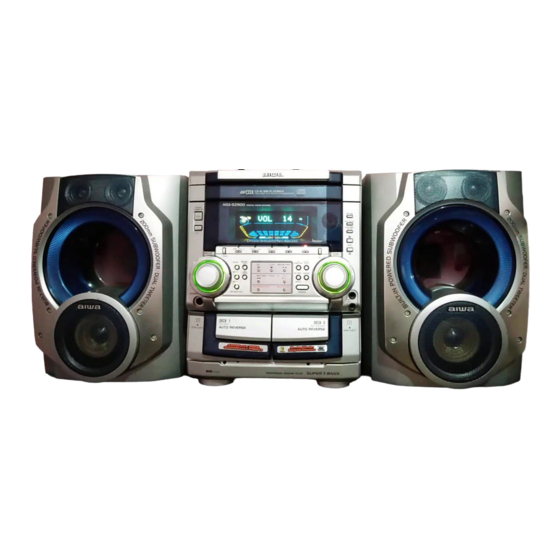
NSX-SZ900
• This Service Manual is the "Revision Publishing" and replaces "Simple Manual"
of CX-NSZ900 (LH), (S/M Code No. 09-013-444-1T1).
• If requiring information about the CD mechanism, see Service Manual of BZG-5,
(S/M Code No. 09-00C-353-3N2).
NSX-SZ900
BASIC TAPE MECHANISM : 2ZM-3MK2 PR7NM
BASIC CD MECHANISM : BZG-5 ZD3N1DM
CD
CASSEIVER
SX-WNSZ900
CX-NSZ900
S/M Code No. 09-015-444-1R1
REMOTE
SPEAKER
CONTROLLER
RC-BAS04
SX-S85
LH
Advertisement
Table of Contents

Related Manuals for Aiwa NSX-SZ900


Summary of Contents for Aiwa NSX-SZ900
- Page 1 All manuals and user guides at all-guides.com NSX-SZ900 SERVICE MANUAL COMPACT DISC BASIC TAPE MECHANISM : 2ZM-3MK2 PR7NM STEREO SYSTEM BASIC CD MECHANISM : BZG-5 ZD3N1DM REMOTE SYSTEM SPEAKER CASSEIVER CONTROLLER SX-WNSZ900 NSX-SZ900 CX-NSZ900 RC-BAS04 SX-S85 • This Service Manual is the “Revision Publishing” and replaces “Simple Manual”...
-
Page 2: Specifications
All manuals and user guides at all-guides.com SPECIFICATIONS <FM tuner section> <CD player section> Tuning range 87.5 MHz to 108 MHz Laser Semiconductor laser (λ = 780 nm) Usable sensitivity (IHF) 13.2 dBf D-A converter 1 bit dual Antenna terminals 75 ohms (unbalanced) Signal-to-noise ratio 85 dB (1 kHz, 0 dB) -
Page 3: Protection Of Eyes From Laser Beam During Servicing
All manuals and user guides at all-guides.com PROTECTION OF EYES FROM LASER BEAM DURING SERVICING This set employs laser. Therefore, be sure to follow carefully CAUTION the instructions below when servicing. Use of controls or adjustments or performance of proce- dures other than those specified herin may result in WARNING!! hazardous radiation exposure. -
Page 4: Note On Before Starting Repair
All manuals and user guides at all-guides.com NOTE ON BEFORE STARTING REPAIR 1. Forced discharge of electrolytic capacitor of power supply block When repair is going to be attempted in the set that uses relay circuit in the power supply block, electric potential is kept charged across the electrolytic capacitors (C101, 102) even though AC power cord is removed. - Page 5 All manuals and user guides at all-guides.com In such a case, check also if the POWER AMPLIFIER circuit or power supply circuit has any abnormalities or not. 2-2. Regarding reset There are cases that the machine does not work correctly because the MICROCOMPUTER is not reset even though the AC power cord is re-inserted, or the software reset (pressing the STOP key + POWER key) is performed.
-
Page 6: Electrical Main Parts List
All manuals and user guides at all-guides.com ELECTRICAL MAIN PARTS LIST REF. NO. PART NO. KANRI DESCRIPTION REF. NO. PART NO. KANRI DESCRIPTION 87-012-368-080 C-CAP,S 0.1-50 Z F 87-012-368-080 C-CAP,S 0.1-50 Z F 8B-NF6-601-030 C-IC,LC876670B-5V72 87-012-368-080 C-CAP,S 0.1-50 Z F 87-A21-911-040 C-IC,M61515FP 87-012-368-080... - Page 7 All manuals and user guides at all-guides.com REF. NO. PART NO. KANRI DESCRIPTION REF. NO. PART NO. KANRI DESCRIPTION C373 87-A10-794-080 C-CAP,U 0.15-16 Z F C638 87-A12-376-080 CAP,M 0.1-100 J CP C374 87-A10-794-080 C-CAP,U 0.15-16 Z F C639 87-A12-091-080 CAP,E 10-50 SMG C378 87-010-831-080 C-CAP,U 0.1-16 Z F...
- Page 8 All manuals and user guides at all-guides.com REF. NO. PART NO. KANRI DESCRIPTION REF. NO. PART NO. KANRI DESCRIPTION C911 87-012-170-080 C-CAP,U 8P-50 D CH L905 88-ZA1-624-010 COIL,FM IFT 7-6.2(COILS) C912 87-012-195-080 C-CAP,U 100P-50 J CH L906 88-ZA1-603-010 COIL,FM-OSC-U 2G C913 87-012-286-080 C-CAP,U 0.01-25 B...
- Page 9 All manuals and user guides at all-guides.com REF. NO. PART NO. KANRI DESCRIPTION REF. NO. PART NO. KANRI DESCRIPTION C921 87-012-270-080 C-CAP,U 470P-50 K B C592 87-012-195-080 C-CAP,U 100P-50 J CH C923 87-010-759-080 C-CAP,U 0.1-25 Z F C593 87-012-195-080 C-CAP,U 100P-50 J CH C925 87-A12-317-080 C-CAP,U 0.1-50 Z F...
- Page 10 All manuals and user guides at all-guides.com REF. NO. PART NO. KANRI DESCRIPTION REF. NO. PART NO. KANRI DESCRIPTION 87-010-759-080 C-CAP,U 0.1-25 Z F C311 87-A12-092-080 CAP,E 22-50 SMG 87-010-759-080 C-CAP,U 0.1-25 Z F C312 87-A12-092-080 CAP,E 22-50 SMG 87-010-759-080 C-CAP,U 0.1-25 Z F C315 87-012-199-080...
-
Page 11: Chip Resistor Part Code
All manuals and user guides at all-guides.com CHIP RESISTOR PART CODE Chip Resistor Part Coding Figure Resistor Code Value of resistor Chip resistor Dimensions (mm) Wattage Type Tolerance Symbol Resistor Code Form 1/16W 1005 0.35 1/16W 1608 0.45 1/10W 2125 1.25 0.45 1/8W... -
Page 12: Transistor Illustration
All manuals and user guides at all-guides.com TRANSISTOR ILLUSTRATION E C B E C B B C E G D S CDA1585BC CC5551 2SB1342 2SK3053 CSC4115BC 2SA1980G 2SB1588 KTA1266GR 2SA1981Y 2SD1933 KTC3198GR 2SD2439 B C E E C B CSB1370EF 2SA933AS(R) 2SK2158 2SK360E... - Page 13 All manuals and user guides at all-guides.com WIRING – 1 (MAIN) – 13 –...
- Page 14 All manuals and user guides at all-guides.com SCHEMATIC DIAGRAM – 1 (MAIN : 1 / 6 <P – SUPPLY SECTION>) – 14 –...
- Page 15 All manuals and user guides at all-guides.com SCHEMATIC DIAGRAM – 2 (MAIN : 2 / 6 <FUNCTION SECTION>) – 15 –...
- Page 16 All manuals and user guides at all-guides.com SCHEMATIC DIAGRAM – 3 (MAIN : 3 / 6 <AMP SECTION>) – 16 –...
- Page 17 All manuals and user guides at all-guides.com SCHEMATIC DIAGRAM – 4 (MAIN : 4 / 6 <DECK SECTION / HEAD – 1 / HEAD – 2>) – 17 –...
- Page 18 All manuals and user guides at all-guides.com SCHEMATIC DIAGRAM – 5 (MAIN : 5 / 6 <DSP SECTION>) – 18 –...
- Page 19 All manuals and user guides at all-guides.com SCHEMATIC DIAGRAM – 6 (MAIN : 6 / 6 <TUNER SECTION>) – 19 –...
- Page 20 All manuals and user guides at all-guides.com WIRING – 2 (FRONT) – 20 –...
- Page 21 All manuals and user guides at all-guides.com WIRING – 3 (KEY) – 21 –...
- Page 22 All manuals and user guides at all-guides.com SCHEMATIC DIAGRAM – 7 (FRONT / KEY / DECK) – 22 –...
- Page 23 All manuals and user guides at all-guides.com WIRING – 4 (AMP 3M) – 23 –...
- Page 24 All manuals and user guides at all-guides.com SCHEMATIC DIAGRAM – 8 (AMP 3M) – 24 –...
- Page 25 All manuals and user guides at all-guides.com WIRING – 5 (PANORAMA AMP) – 25 –...
- Page 26 All manuals and user guides at all-guides.com SCHEMATIC DIAGRAM – 9 (PANORAMA AMP) – 26 –...
- Page 27 All manuals and user guides at all-guides.com WIRING – 6 (PT) – 27 –...
- Page 28 All manuals and user guides at all-guides.com SCHEMATIC DIAGRAM – 10 (PT) – 28 –...
- Page 29 All manuals and user guides at all-guides.com WIRING – 7 (DECK / HEAD – 1 / HEAD – 2) – 29 –...
- Page 30 All manuals and user guides at all-guides.com FL (BJ815GNK) GRID ASSIGNMENT / PIN CONNECTION / ANODE CONNECTION GRID ASSIGNMENT PIN CONNECTION – 30 –...
- Page 31 All manuals and user guides at all-guides.com ANODE CONNECTION NOTE: = (UP) = (DOWN) – 31 –...
- Page 32 All manuals and user guides at all-guides.com IC BLOCK DIAGRAM – 32 –...
- Page 33 All manuals and user guides at all-guides.com – 33 –...
- Page 34 All manuals and user guides at all-guides.com IC DESCRIPTION IC, LC876670B–5V72 Pin No. Pin Name Description I–SUBQ CD sub-code input. O–BUZ Touch-sensor beep sound output. (Not used) O–MOTOR Tape motor ON/OFF. O–SOL1 Tape 1 plunger ON/OFF. O–SOL2 Tape 2 plunger ON/OFF. O–RSM–CE Rhythm IC chip enable output.
- Page 35 All manuals and user guides at all-guides.com Pin No. Pin Name Description DOLBY / P19 DOLBY enable diode input (Not used) / FL segment P19 output. CASINO / P18 Casino DEMO diode input / FL segment P18 output. KARAOKE / P17 Karaoke enable diode input (Not used) / FL segment P17 output.
- Page 36 All manuals and user guides at all-guides.com ADJUSTMENT < DECK / TUNER / FRONT > G DECK C.B SFR1 A MAIN C.B SFR351 SFR352 J101 <DECK SECTION> 1. Adjusting Tape Speed (DECK 2) Requirements • Measuring Device: WOW & FLUTTER Meter (Frequency Counter) Test Tape: TTA-100 (3 kHz) Test Point: HP OUT (J101) Adjustment Point: SFR 1...
- Page 37 All manuals and user guides at all-guides.com 3. Checking WOW & FLUTTER (DECK 1, DECK 2) Requirements Same as number 1 1) Connect the WOW & FLUTTER Meter to the HP OUT. 2) Set the indicator to JIS and the mode to W RMS (WTD) of the WOW & FLUTTER. 3) Playback the centre of the test tape (TTA-100) and check that it is below 0.21 %.
- Page 38 All manuals and user guides at all-guides.com 2) Connect the output from the generator to the attenuator and connect the AUX from the set to the attenuator. 3) Insert the tape (TTA-602) into DECK 2 and record the 1 kHz signal from AUX. 4) At this time, adjust the attenuator until TP8 and TP9 output levels become 21 mV.
- Page 39 All manuals and user guides at all-guides.com < TUNER SECTION > 1. Clock Frequency Check 8. Output Level Check Settings : • Test point : TP11 (CLK) <AM> Method : Set to AM 1710 kHz and check that the test point is Settings : •...
-
Page 40: Cd Test Mode
All manuals and user guides at all-guides.com CD TEST MODE 1. How to Activate CD Test Mode While pressing the FUNCTION button, insert the AC plug to the power outlet. When the test mode is started, the message “ TEST” is displayed. 2. - Page 41 All manuals and user guides at all-guides.com MECHANICAL EXPLODED VIEW 1 / 1 PLATE,SHILD SIDE BZG-5 HT-SINK,FET HT-SINK BINDER WIRE PLATE,PT 2ZM-3MK2 PLATE,EARTH MECH CHAS,MAIN – 41 –...
-
Page 42: Mechanical Parts List
12 8B-NF6-041-010 CABI,FR H 52 87-NF4-221-010 HLDR,CABLE 13 8B-NF6-061-010 WINDOW,DISPLAY H 53 87-A80-092-010 AC CORD ASSY,E BLK SUN FAI 14 87-CE3-023-010 BADGE,AIWA 30N SILV 54 87-085-185-010 BUSHING, AC CORD (E) 15 8B-NF6-010-010 PANEL,CD 55 8B-NF6-033-010 PANEL,RIGHT V-2 16 8B-NF6-005-010 WINDOW,CD 56 88-915-181-110 FF-CABLE,15P 1.25... - Page 43 All manuals and user guides at all-guides.com TAPE MECHANISM EXPLODED VIEW 1 / 1 PLATE SHLD,M3 GEAR, PLAY GEAR, PLAY PLATE SHLD,M3 – 43 –...
-
Page 44: Tape Mechanism Parts List
All manuals and user guides at all-guides.com TAPE MECHANISM PARTS LIST 1 / 1 REF. NO. PART NO. KANRI DESCRIPTION REF. NO. PART NO. KANRI DESCRIPTION 1 82-ZM3-335-310 PULLEY,COUPLER M3 36 82-ZM3-340-010 SH,BELT D2 2 87-B10-043-010 W-P,0.99-4-0.25 SLT 37 82-ZM1-242-010 LVR,CAS 3 86-ZM1-206-010 BELT,MAIN L... -
Page 45: General Speaker Disassembly Instructions (For Reference)
All manuals and user guides at all-guides.com GENERAL SPEAKER DISASSEMBLY INSTRUCTIONS (FOR REFERENCE) Type.1 Type.4 Insert a flat-bladed screwdriver into the position indicated by the TOOLS arrows and remove the panel. Remove the screws of each speaker 1 Plastic head hammer unit and then remove the speaker units. -
Page 46: Accessories / Package List
All manuals and user guides at all-guides.com SPEAKER PARTS LIST (SX-WNSZ900) <YLSL> REF. NO. PART NO. KANRI DESCRIPTION 1 8B-NS6-001-010 PANEL,FR A 2 8B-NS7-002-010 PANEL,SP A 3 8B-NS7-003-010 PANEL,SP B 4 8B-NS7-005-010 PANEL,BA A 5 8B-NS7-004-010 PANEL,DUCT 6 8B-NS8-007-010 PROTECTOR,M 7 8B-NS6-604-010 SPKR,W 200 40/4 8 8B-NS7-604-010... - Page 47 All manuals and user guides at all-guides.com 2–11, IKENOHATA 1–CHOME, TAITO-KU, TOKYO 110, JAPAN TEL:03 (3827) 3111 2000075 921338 Printed in Singapore...
Need help?
Do you have a question about the NSX-SZ900 and is the answer not in the manual?
Questions and answers