Table of Contents
Advertisement
Quick Links
Download this manual
See also:
User Manual
Advertisement
Table of Contents

Subscribe to Our Youtube Channel
Related Manuals for InWin IW-RS212-07


Summary of Contents for InWin IW-RS212-07
- Page 1 IW- - - - RS212 RS212 RS212 RS212- - - - 07 U s e r M a n u a l U s e r M a n u a l U s e r M a n u a l U s e r M a n u a l...
-
Page 2: Table Of Contents
Table of Contents PREFACE ............................1 SAFETY INFORMATION ......................... 1 CAUTION ............................2 SPECIFICATIONS ..........................3 12Gb/s BACKPLANE SPECIFICATIONS .................... 4 Product Introduction ......................5 Box Contents ......................... 5 Accessories Box ......................6 General Information ...................... 7 1.3.1 Front Panel Controls and Indicators ................. 8 1.3.2 Rear Panel Configuration .................... - Page 3 Backplane Introduction ....................... 18 Compatibility Lists ......................19 Q & A ..........................20 Technical Support ........................ 21...
-
Page 4: Preface
InWin’s server website. SAFETY INFORMATION To ensure a safe and smooth operation of your InWin IW-RS212-07, it is essential that you choose an appropriate location for the system, provide an appropriate operating environment and supply an adequate amount of power for all components of the system. As you plan for installation, follow the guidelines below to ensure that the system and its environment are safely and appropriately positioned for efficient operation and service. -
Page 5: Caution
Installing or Removing Jumpers: A jumper is a short length conductor used to close, open or bypass part of an electronic circuit. Jumpers on InWin backplanes have a small tab on top that you can pick up with your fingertips. Grip the jumper carefully and plug the jumper to cover the jumper pins on the backplane. -
Page 6: Specifications
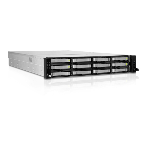
• HQ: 414pcs The actual product is subject to change without prior notice. InWin Development Inc. reserves the right to make any final modifications. The adjacent image is for reference only. All hardware components and optional parts are not included. -
Page 7: 12Gb/S Backplane Specifications
Product Dimensions 12Gb/s BACKPLANE SPECIFICATIONS Slimline Backplane Backplane- - - - 1 405mm x 72.3mm Dimensions (W x H) Active with expander onboard Backplane Type 3 x SFF-8643 4 x SFF-8654 Slimline Host Interface 12 x SAS/SATA or 8 x SAS/SATA and 4 x NVMe SSD HDD Interface Oculink Backplane Backplane- - - - 2... -
Page 8: Product Introduction
Product Introduction Box Contents When you open the IW-RS212-07 box, the contents should include following:... -
Page 9: Accessories Box
Accessories Box Name Name Accessories Box Label x 1 Motherboard Stand-off Sockets x 12 Power LED 3-pin to 2-pin Adapter x 1 Hexagon Head Screws x 12 Cable Ties and Mounts x 5 2.5" HDD Screws x 36... -
Page 10: General Information
General Information When you open the chassis, it should reflect the diagram’s image. -
Page 11: Front Panel Controls And Indicators
1.3.1 Front Panel Controls and Indicators The IW-RS212-07 supports either 3.5" SAS/SATA disk bays x 12 or 3.5" SAS/SATA disk bays x 8 + NVMe 4 x 3.5" disk bays in specific areas. The control panel, USB I/O ports and indicators are located on the handles. -
Page 12: Rear Panel Configuration
Description Power Module 1 Default primary power supply module. Power Module 2 Backup power supply module. This slot is for InWin OS disk backup module (optional), which OS HDD supports two 2.5" 12G SSDs and features hot-swap function. System I/O... -
Page 13: Hardware Installation
07 Series Motherboard & Expansion Card. HDD Tray Installation The IW-RS212-07 features tool-less trays. Users no longer need to use screws to mount disks, and can swap drives faster. For a quick installation video, please visit 07 Series HDD Tray Installation. -
Page 14: Power Supply Cable Information
2.4.1 Power Supply Cable Information Length Unit: mm... -
Page 15: Connecting Cables
2.5 Connecting Cables InWin backplanes with expander onboard are high performance and are cost-effective solutions for supporting Intel® Xeon Scalable family by adding NVMe support. The active backplanes support state-of-the-art SAS3 12Gbps HDD/SSD and are also backward compatible with SAS 6Gbps, SATA 6Gps and SATA 3Gps HDD/SSD. Some of the backplanes support NVMe SSDs through either Oculink x 4 or Slimline x 4 connectors. -
Page 16: Connecting Led Cable, Front Control Panel And Front Usb I/O Ports
2.5.2 Connecting LED Cable, Front Control Panel and Front USB I/O Ports Refer to your motherboard user guide for pin functions and locations, and then plug the connectors to the pins on the motherboard to activate the functions. USB 3.0 LED Connector Connector Name Abbreviation Color... -
Page 17: Installing The Slide Rail
2.6 Installing the Slide Rail The IW-RS212-07 is a rackmount model, which supports EIA-RS310D standard cabinets and chassis racks. InWin provides standard slide rails to allow users to mount the chassis onto the cabinets. 2.6.1 Identifying the Slide Rail The slide rail by your order might be different. You can reference the quick installation guide inside the slide rail package and follow the instructions to mount the rail onto your cabinet or chassis rack. -
Page 18: Mounting The Rail Bracket To The Cabinet
Step 1 - 2 Step 3 2.6.4 Mounting the Rail Bracket to the Cabinet Step 1: Extend the rail bracket over the rear rack of the cabinet. Step 2: Pull out the rear hook on the end of the outer rail, align and push the rail bracket pins into the post holes on the rack. -
Page 19: Inserting The Chassis To The Cabinet
Step 1 - 5 Step 6 2.6.5 Inserting the Chassis to the Cabinet Step 1: Pull out the middle rail to the stop position. Step 2: Move the ball bearing retainer to the front end of the middle rail, and it should click into the locked position. - Page 21 Backplane Introduction The backplane varies by order. Please reference the backplane user guide to complete the installation. The download link is at the download section of each product. Please visit the InWin website: ipc.in-win.com. Oculink Backplane for NVMe Top Side...
- Page 22 To reach the best performance and avoid system failure, InWin strongly recommends customers to choose the components from InWin’s compatibility list. All the components are tested in InWin’s lab, and assured the components are compatible with InWin’s chassis. You can...
- Page 23 Does the backplane support 6Gb SAS? A: The InWin IW-RS212-07 is accommodated with 12Gb SAS backplane by default. The 12Gb SAS connector interface (SFF-8643) is not compatible with 6Gb SAS. InWin provides OEM/ODM services, so may contact their local InWin sales reps for customization.
- Page 24 You can buy the verified cable from InWin to eliminate compatibility issues. Technical Support If you need help with installation or troubleshooting, you can contact your local InWin reps, or send an e-mail to InWin’s local contacts for technical assistance.
Need help?
Do you have a question about the IW-RS212-07 and is the answer not in the manual?
Questions and answers