
Related Manuals for Light Sky IP Aquabeam Series


Summary of Contents for Light Sky IP Aquabeam Series
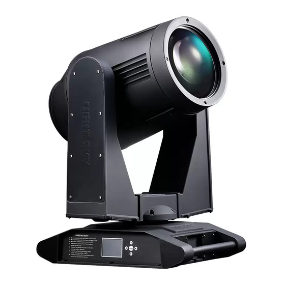
- Page 1 Service Manual Product serie: IP serie Product mode: IP1000E、IP2000、IP2000E、 Aquabeam IP3000、IP3000E WWW.lightsky.com.cn...
- Page 2 Contents catalogue 1.The installation and routine maintenance....................2 2. The maintenance method and attentions....................3 3. The treatment of exceptional falt.......................4 4. The exploded view............................8 IP300 0 lamp dismounting and mounting....................22 6. IP series X Motor replacement.......................24 7. IP series Y Motor replacement........................28 8.
- Page 3 The installation and routine maintenance 1. The installation and use: Please read carefully with the lights attached ‘User Manual’, in strict accordance with the related manual content to guide the installation and use. 2. To install and use the lights, pay attention to the following points: ◆...
- Page 4 Maintenance methods and attentions 1. Cleaning period: In order to ensure the light fixture to be operated normally, it should keep the lights clean, the cleaning period generally is one month, if the light is used in a environment with dust ,or near to the smoke machine, bubble machine or snow machine, the cleaning period should be shortened.
- Page 5 Faulty issues Maintenance The following are the common faulty issues of lights and the corresponding treatments. All the repairs shall be handled by professional technician. all the fixtures must be Switch off before maintenance. 1. Faulty issue 1 : Lamp can not TURN ON ◎...
- Page 6 3.Faulty issue 3: The spot is off-center, dark, uneven: Troubleshooting: ◎ Check if the lamp come to the end of service life which cause the brightness insufficient,replace the same model lamp . ◎ Check if there is dust on the optical components, clean it. ◎...
- Page 7 6.Faulty Issue 6: The Gobo wheel, color wheel or CMY module is stuck, or with shaking,stepping out and out of control performance Troubleshooting: ◎ The stuck issue is usually caused by the mechanical reasons, such as the Gobo wheel or color wheel is deformed , the screw is loose etc.
- Page 8 8. Faulty Isssue 8: the PAN/TILT direction out of step, no position correct, bad synchronization Troubleshooting: ◎ Check if the PAN/TILT sensor are covered with too much dust , clean it water-free alcohol. ◎ Check if the PAN/TILT sensor are damaged. when POWER ON, manually move the Pan/ Tiltbut no reset, it means the PAN/TILT sensor are damaged, then replace the new ones.
-
Page 9: Exploded View
Exploded view Brief exploded view Head module U- a rm m o du l e Base module... - Page 10 Base exploded view Item number 1: M1300767 2: M03014008 3: M1300768 4: M01028005 5: M01028003 6: M02028018 7: M02028001 8: M23020003 09: M01028002 10: M1200101(Fan,6*6) 11: M1000962(600W power supply) 12: M1200101(Fan,6*6) 13: M1200111((Fan,IP3000) 14: M1000954A(150W power supply) 15: Z0600100099(X/Y board) 16: M1501230(E-ballast)...
- Page 11 X motor cable X sensor cable Signal cable Y sensor cable Y motor cable X 1 Y 1 BUS BUS1 Base 12V fan cable U-arm 24V fan cable X/Y PCB power cable Base 24V fan cable M10 0 09 6 2 Item number: RUP600F380A X/ Y PC B p ar t...
- Page 12 U-ar m exploded view Item number 1: M 01 028 012 2: M0 301 4013A 3: M0 301 4007 4: M03 01 4011 5: M03 01 4006 6: M03 01 4013A 7: M02 02 8027 8: M 01 02 8016 9: M 02 028013 10: M0 202 8005A 11: M12 00 521(Fan)...
- Page 13 Y sensor cable:Y1 U-arm fan cable motor cable Head power & signal cable U-arm fan M1200521( Fan) Lamp cable/ earth wire X sensor cable:X1 X sensor cable:X...
- Page 14 Head exploded view Lens module 1. M03014001 2. M02028006A 3. M03014004 Focus module Functions module 4. M03014002 5. M03014005...
- Page 15 Focus& lens exploded view Item number 1:M03014003 2:M0200915 3:M0600237(fro nt le n s) 4:M03014009 5:M02028016 6:M0202535 7:M01028017 8:M02025166 9:M0600238(back lens) 10:M02025167 11:M01028018 12:M02028014 13:M0500613(motor) 14:M02028015 15:M0202535 16:M02028017...
- Page 16 Prism exploded view Item number 1:32facet prism(8+24prism) 2:M02025161(prism) 3: M1100311 4: M0800218K 5: M0202573K 6: Frost Module 7: M0300795 8: M0202565 9: M0202572K 10:M01028022 11:M0202581 12:M0202574K 13:M0500637 14:M0500637(motor) 15:M0500637(motor) 16:M0500619(motor) 17:M0500618K(motor) 18:M0202575K 19:M0800217K 20:M0202572K 21:M01025100 22: M0202568 23:M0600335...
- Page 17 Gobo exploded view Item number 1:Fix ati on G o bo 2:M0 500 64 2A ( m o t o r) 3: Z 0 600 100 09 0 4: s tro be 5 : M 01 028 03 4 6: M 0 500 13 0(m o t o r) 7: M 020 260 41 D Gobo module 8: M 05 00 624 ( m o t o r)...
- Page 18 Prism& frost cables list I t e m n u m b e r length m ar k Cable name 2 0 c m M 1 9 2 5 6 D 0 2 0 Prism 1 motor cable 3 5 c m M 1 9 2 5 6 D 0 3 2 Prism 2 motor cable 1 0 c m...
- Page 19 Color& CMY exploded view Item number 1:M01028032 2:Z0600400015 3: M01025137 4: M02028025 5: Color wheel 6: M02028025 8: M02028026 10:M02028026 11:C 12:M02028026 13:M0202189 14:M02028026 15:M01028031 16: M0202 8 0 1 9 17:M1200801A(Fan)...
- Page 20 Light source exploded view Item number 1:M0202198 2:M0202157 3: M01028039 4: M1801026(heat filter) 5: M02028024 6: M01028035 7: M03014010 8: M0500641A (motor) 9: M1200513A(Fan) 10: M01028037 11: Z0600638(adaptor 1) 12: M01028049 13:M1604104A(TDS(temperature switch)) 14:M1699943(Temperature sensor) 15:M1200513A(Fan) 16:M1200306A(Fan) 17:M01028054 18:M0202196 19:M01028023 20:Z0600638A(adaptor 2)...
- Page 21 7M driver board power cable FAN3-1 E D C B FAN3-2 FAN1 FAN3 FAN4 FAN5 FAN3-1 FAN3-2 F A N 1 F AN5 F A N 3 Gobo f a n lam p f a n 2 bac k 9 2 2 5 F A N 4 lamp f an 1 swit c h...
- Page 22 FAN1 Gobo / color / light source cable list: C abl e name I t e m n u m b e r Mark P r i s m m o t o r c a b l e M 1 9 2 5 6 D 0 1 0 M 1 9 2 4 4 D 0 2 0 F o c u s m o t o r c a b l e 1 M 1 9 1 7 8 D 0 2 2...
- Page 23 Lamp’s installation and dismantle Step 1: Disconnect with the power, make sure the lamp is cool. Step 2: loose 6 screws as Pic 1,but no need take the screws out and open the cover. Pic 1 Step 3: dismantle the 4 screws as Pic2, pull out the fan cable as Pic3, move the fan module away.
- Page 24 Step 5: pull out the lamp power cable as the arrow direction in Pic 5, loose the 4 pcs fixed screw (no need to take the screw out),replace the lamp. Pic5 Step 6: After Finished the lamp replacement, repeat step5 , 4 ,3 ,2 ,1 , and make sure all the connector and cables are in original place and good contact.
- Page 25 IP series X motor replacement 1. Unscrew the screws, open the arm cover.
- Page 26 2. Open the axis cover , then you will see the cables. 3, Dismantle the METAL STICK,which is near to the X belt. And clockwise turn 90 degree of the marked cover. (the second photo is how it look like after colorwise 90 degree ). after 90°degree rotation to the other side...
- Page 27 4. Dismantle those fixed M5 screw of Pan Motor. M5 screw position 5. After dismantle the fixed screws of PAN MOTOR , like the phot shows , turn the gear into different position ,and dismantle the gear , and get out of gear , then you can take out the PAN motor.
-
Page 28: Pan Sensor
6.Replace the Pan Motor, here are two position need to pay attention A, Motor ROAD must keep balance with Motor axis B, gear can not be fixed in advance , but must keep in its position to make sure the X sensor is in its centor position. - Page 29 IP series Y motor replacement 1. Dismantle those screws ,and open the marked covers.
- Page 30 2.Open the axis cover , then you will see the cables. 3.Dismantle the METAL STICK,which is near to the X belt. And clockwise turn 90 degree of the marked cover. (the second photo is how it look like after colorwise 90 degree ). clockwise turn 90 degree position...
- Page 31 4. Put down the fixture with side arm face you, dismantle these 4 pcs fixed screw of PAN MOTOR. Make the handle up 5.After dismantle the screws , and take out the Y Belt according to the arrow direction shows.
- Page 32 6. Dismantle the Y sensor and gear set. put down the motor set and makethe gear point to base cover direction,then,you can dismantle the gear Y motor sensor 7. Dismantle Y motor fixed metal. then, get out the Y motor. Y motor sensor...
- Page 33 8. When replace the Y motor , there are 4 points need to pay attention, A, Please remember to connect the motor cable when you replace the Y motor Motor cables B, the 4pcs Pad hole and Pad must be fit perfectly before fix the screws of Y motor. 4 pcs Pad Hole...
- Page 34 Please note the Motor Road must be have a safety space with Motor to avoid the motor be stuck. And Y gear should be in the centre postion of Y motor sensor , and make sure the cables are well connected and screws are well fixed. C e n t e r p o s i t i o n fix the screw Safty space...
- Page 35 IP series, X/Y motor driver board replacement 1. Dismount the bottom cover screws and open it. 2. Screw off the 2pcs M3 screws as the picture below, take the X/Y board out.
- Page 36 3 . P C B c a b l e s l i s t . Y optocoupler cable Y motor cable Signal cable X motor cable X optocoupler cable Base box 24V fan cable X 1 Y 1 BUS BUS1 X/Y board power cable Base box 12V fans cable U-arm 24V fans cable...
- Page 37 IP series CMY and color wheel replacement Step 1 : as following pics show A: Open the base cover B: Pull out SW, TEM, BUS1, B, FAN and AC in cables . Pull out all the cables show in the photo.
- Page 38 Step3 , as Above photos show, (for safety ) A, Dismantle those 4 pcs screws for the Fan, and get out of the fan. B, Dismantle another 4 pcs screw for the lamp , and get out of the lamp C, Dismantle the shutter plate.
- Page 39 Step 5 as Above photos show A, Firstly , Dismantle these two Mini green PCB’s screws , each PCB board , 2pcs screws. B, Secondly , Dismantle those 4 pcs M3 screws. C, Dismantle those 4 pcs M 4 screws D, take out of the CMY filter module.
- Page 40 Step 7, as Above photos show A, Take out those Pads, color wheel , and Y, C, M according to the installation sequence of the filter according to your repairing request. When you need to install the CMY or color wheel , just repeat 7, 6.
Need help?
Do you have a question about the IP Aquabeam Series and is the answer not in the manual?
Questions and answers