
Related Manuals for QUNDIS Qheat5


Summary of Contents for QUNDIS Qheat5
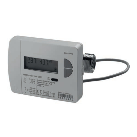
- Page 1 Installation manual Only for trained experts IMPORTANT! READ THROUGH CAREFULLY BEFORE USE. KEEP ACCESSIBLE THROUGHOUT THE PRODUCT LIFETIME. Heat meter Screw-type meter (QDS)
- Page 2 Scope of delivery Heat meter 2 protective caps Installation manual Operating manual User information for stock immersion sleeves (only for D) Flow sensor kit Temperature sensor kit Control cable kit The control cable with screws and seals is only part of the scope of supply for the heat meter with integrated communication interface.
-
Page 3: Table Of Contents
Contents Safety and warranty ..................5 Important information ................5 Technical data ....................6 Technical data for integrated communication ..........8 Connection cable ..................9 Design length 80 mm ..................9 Design length 110 mm ................10 Design length 130 mm ................10 Dimensional drawings .................11 Design length 80 mm ...................11 Design length 110 mm ................ - Page 4 Contents Installing temperature sensor - indirectly immersed (immersion sleeve) 24 Wall installation with removable calculator unit ........25 Checking installation .................. 26 Opening the valves ..................26 Checking installation ................... 26 Sealing the device ..................27 Sealing flow sensors ................... 27 Sealing the temperature sensor in a ball valve ...........
-
Page 5: Safety And Warranty
Safety and warranty Important information This product must be installed professionally and in accordance with the pre- scribed assembly guidelines and may therefore only be installed by qualified and trained experts. Intended use Heat meters are for the centralized recording of the consumption of heat energy or cooling energy. -
Page 6: Technical Data
Technical data Norms and standards Conformity see EU Declaration of Conformity Protection rating IP protection rating IP65 according to EN 60529 Heat meter European Measuring Instruments Directive (MID) 2004/22/EC EC-type examination certifi cate DE-12-MI004-PTB009 Heat meter CEN EN1434 Quality of heat medium in accordance with VDI guideline 2035 in accordance with AGFW standard 510 Infl... - Page 7 Technical data Flow sensor screw-type meter Connection sizes and dimensions 0.6 m³/h 1.5 m³/h 1.5 m³/h 2.5 m³/h Length 110 mm 80 mm 110 mm 130 mm Connection G ¾ B G ¾ B G ¾ B G 1 B Weight compact 668 g...
-
Page 8: Technical Data For Integrated Communication
Devices with integrated communication interface Technical data for integrated communication Connection cable “OUT” “IN” Function M-Bus Impulse inputs Length Included in scope Included in scope of Supply of supply supply of order option Protection class IP65 Wire ends Wire-end ferrules Cable sheathing Colour assignment connection cable Impulse input... -
Page 9: Connection Cable
Devices with integrated communication interface Connection cable 1000 3000 Design length 80 mm 1 : 1 (Maßstab) (Gewicht (Verwendungbereich) Allgemein- Tolerierungsgrundsatz Toleranz (Werkstoff)) nach ISO 8015 ISO 2768-mH Datum (Benennung) Name HMR5x / CMR5 15.03.16 Schwarz Bearb. Qheat 5 COM Dimensions in mm. -
Page 10: Design Length 110 Mm
Devices with integrated communication interface Design length 110 mm 1 : 1 (Verwendungbereich) (Maßstab) Allgemein- Tolerierungsgrundsatz Toleranz (Werkstoff)) nach ISO 8015 ISO 2768-mH Design length 130 mm Datum (Benennung) Name HMR5x / CM 15.03.16 Schwarz Bearb. Qheat 5 C Gepr. - Bauhöh Norm (Firma, Zeichnungs-Ersteller) -
Page 11: Dimensional Drawings
Dimensional drawings Design length 80 mm 101,5 Ø 50 Dimensions in mm. -
Page 12: Design Length 110 Mm
Dimensional drawings Design length 110 mm 101,5 Ø 50 Dimensions in mm. -
Page 13: Design Length 130 Mm
Dimensional drawings Design length 130 mm 101,5 Dimensions in mm. -
Page 14: Important Installation Notes
Important installation notes The sensor cables (e.g. temperature sensor cable) must be routed at a distance of at least 50 mm to sources of electro- magnetic interference (switches, electric motors, fluorescent lamps). An installed meter is a pressurized component. Risk of scolds from hot water. Fitting only by trained experts. -
Page 15: Installation Positions
Installation positions Horizontal installation Vertical installation Tilted horizontal installation No overhead installation! -
Page 16: Installation Variants - Directly Immersed (Ball Valve)
Installation variants - directly immersed (ball valve) Heat meter design lengths 110 mm / 130 mm • Return fl ow sensor integrated in the fl ow sensor • Supply fl ow sensor directly immersed Heat meter design length 80 mm •... -
Page 17: Installation Variants - Indirectly Immersed (Immersion Sleeve)
Installation variants - indirectly immersed (immersion sleeve) Heat meter design lengths 110 mm / 130 mm Note national and country-specifi c regulations concerning the use of immersion sleeves. • Return fl ow sensor integrated in the fl ow sensor • Supply fl ow sensor indirectly immersed Heat meter design length 80 mm Note national and country-specifi c regulations concerning the use of immersion... -
Page 18: Preparing Installation - Directly Immersed (Ball Valve)
Preparing installation - directly immersed (ball valve) - for new installation • Flush the system • Close ball valves With 80 mm variant (no integrated return fl ow sensor) Use ball valve with temperature sensor slot! Use ball valve with connection for directly immersed supply fl ow sensor. -
Page 19: Installing Heat Meter - Directly Immersed (Ball Valve)
Installing heat meter - directly immersed (ball valve) Prepare installation • Remove the fl ushing tube or existing meter • Remove old seals • Dismantle temperature sensor if appropriate Fit the heat meter • Remove threaded protective caps • Always use new seals when installing a new meter. -
Page 20: Installing Temperature Sensor - Directly Immersed (Ball Valve)
Installing temperature sensor - directly immersed (ball valve) Temperature sensors – diameter 5.0 mm / 5.2 mm Carry out steps 1-4 with the position P1 shown for the temperature sensor (TF) in the half-shell screw fi tting. (1) Insert the temperature sensor in the half-shell screw fi tting enclosed. -
Page 21: Temperature Sensor - Agfw
Installing temperature sensor - directly immersed (ball valve) Temperature sensor – AGFW (1) Screw the temperature sensor hand-tight into the installation point. Immersion depth > 50 % (2) Tighten the sensor screw fitting with a tightening torque of approx. 5 Nm using a wrench. -
Page 22: Preparing Installation - Indirectly Immersed (Immersion Sleeve)
Preparing installation - indirectly immersed (immersion sleeve) - for new installation Note national and country-specifi c regulations concerning the use of immersion sleeves. • Flush the system • Close ball valves With the 80 mm variant (no integrated return fl ow sensor): Use muffs with immersion sleeves. -
Page 23: Installing Heat Meter - Indirectly Immersed (Immersion Sleeve)
Installing heat meter - indirectly immersed (immersion sleeve) Prepare installation Note national and country-specifi c regulations concerning the use of immersion sleeves. concerning the use of immersion sleeves. • Remove the fl ushing tube or existing meter • Remove old seals •... -
Page 24: Installing Temperature Sensor - Indirectly Immersed (Immersion Sleeve)
Installing temperature sensor - indirectly immersed (immersion sleeve) Note national and country-specific regulations concerning the use of immersion sleeves. In EU states (except Germany) immersion sleeves are also approved for new installations if they are MID-conform. Immersion sleeves are not approved for new installations in Germany. For replacement installations, note and follow the enclosed user information for stock immersion sleeves. -
Page 25: Wall Installation With Removable Calculator Unit
Wall installation with removable calculator unit Variants with removable calculator unit can be installed up to max. 40 cm away from the fl ow sensor using the optional wall bracket. (1) Attach the spacer (a) and wall bracket (b) in the required position using the enclosed material. -
Page 26: Checking Installation
Checking installation Opening the valves • Open the ball valves • Switch the heating on and open the radiator valve Checking installation • Check leak tightness and direction of fl ow Incorrect direction of fl ow is shown on the display. -
Page 27: Sealing The Device
Sealing the device Sealing fl ow sensors (1) Thread the seal wire through the seal holes in the union nut on the inlet and on the fl ow sensor. (2) Insert the wire through the available opening in the seal body. (3) Wind the wire tightly by turning the wing in the seal. -
Page 28: Sealing The Temperature Sensor In An Immersion Sleeve
Sealing the device Sealing the temperature sensor in an immersion sleeve Note national and country-specifi c regulations concerning the use of immersion sleeves. concerning the use of immersion sleeves. (1) Thread the wire of the seal through the seal holes on the threaded sensor fi tting and immersion sleeve. -
Page 29: Operation And Display
Operation and display Device elements (1) LC display The display is off as standard (sleep mode). The display can be activated by pressing a key. (2) Key < H > (horizontal) (3) Key < V > (vertical) (4) IrDA interface (5) Interface cover (6) Module interface (7) Attachment holes for external optical mod-... -
Page 30: Special Operating States
Operation and display Special operating states Display Description Measures/Notes • Communication credit • Is eliminated after the credit period of the module interface (module = current day; IrDA = current or IrDA exceeded month) has passed. • Operating time • Device must be replaced expired •... -
Page 31: Navigating Within The Levels
Operation and display Navigating within the levels 1. To open the display loop or level operating scheme Press the < H > or < V > key briefl y to open the fast readout display loop. Press the < H > or < V > key longer than 3 seconds to open the level operating scheme. -
Page 32: Commissioning
Commissioning To activate programming mode Use the < H > key to navigate to the respective display level (L3 or L4). Use the < V > key to display the respective value (here: due date). Activate programming mode using the key combination < H > + < V > . -
Page 33: Example: Activate / Deactivate Levels
Commissioning Example: Activate / deactivate levels Display level L3 - display "possible + active levels" Activate programming mode using the key combination < H > + < V > . When programming mode (see pagePage 31) is activated, the "M-" symbol will flash. Press the <... -
Page 34: Example: Changing The Dimensioning Unit (Kwh < -- > Mwh Or Mj < -- > Gj)
Commissioning Example: Changing the dimensioning unit (kWh < -- > MWh or MJ < -- > GJ) Display level L3 - display "possible + active levels" Activate programming mode using the key combination < H > + < V > . -
Page 35: Installation Suggestions
Installation suggestions (1) Installation in a part of the secondary circuit that is not constantly under fl ow. (2) Installation in a part of the primary circuit that is not constantly under fl ow. Water only fl ows through the heat meter when hot supply water from the primary circuit fl ows into the secondary circuit via the three-way mixing valve. -
Page 36: Checklist
Checklist Heed national and country-specific regulations! Before installation 1. Are the security points on the meter undamaged? (seal on the return flow meter, seal) 2. Is there a suitable installation kit available? (ball valves, installation parts, seals) 3. Is the installation kit in the right place? 4. -
Page 37: After Installation
Checklist After installation 1. Have the temperature sensors (supply flow / return flow sensors) been installed in the respective pipes? 2. In addition where immersion sleeves are used: Has the sensor been pushed to the base of the immersion sleeve and screwed in place tightly? 3. -
Page 38: Information About Heat Meter Add-On Modules
Information about heat meter add-on modules Use of combined heat/cold meters with add-on module Add-on modules cannot be used with heat meters with an integrated communication interface. With the introduction of the new heat meter generation, the housing colour of the heat meter add-on modules has been changed from blue to white. -
Page 39: R99/0005-02 - M-Bus Add-On Module
Information about heat meter add-on modules Example: Printed on heat meter: Serial no. heat: 65 000 100 Serial no. for cold: 65 000 101 The following system ID is generated from the serial no. for heat: System ID channel 1: 65 000 100 for heat System ID channel 2: 62 000 100 for cold... - Page 40 FIM5-ZZHE-GB0-HMQDS - 21.3.2016 / V3.0...
Need help?
Do you have a question about the Qheat5 and is the answer not in the manual?
Questions and answers