Advertisement
Quick Links
964#'LJLWDO
6HUYR#'ULYH
3URGXFW#0DQXDO
+$79<3498334#,VVXH#%
&RPSDWLEOH#ZLWK#($6<5,'(5#9HUVLRQ#81[#6RIWZDUH
©#&RS\ULJKW#(XURWKHUP#'ULYHV#/LPLWHG#4<<<
All rights strictly reserved. No part of this document may be stored in a retrieval system, or transmitted in any form or
by any means to persons not employed by a Eurotherm group company without written permission from Eurotherm
Drives Ltd.
Although every effort has been taken to ensure the accuracy of this document it may be necessary, without notice, to
make amendments or correct omissions. Eurotherm Drives cannot accept responsibility for damage, injury, or expenses
resulting therefrom.
( 8 5 2 7 + ( 5 0
' 5 , 9 ( 6
Advertisement

Subscribe to Our Youtube Channel
Related Manuals for Eurotherm Drives 631

Summary of Contents for Eurotherm Drives 631
- Page 1 Eurotherm group company without written permission from Eurotherm Drives Ltd. Although every effort has been taken to ensure the accuracy of this document it may be necessary, without notice, to make amendments or correct omissions. Eurotherm Drives cannot accept responsibility for damage, injury, or expenses resulting therefrom.
- Page 2 Eurotherm Drives warrants the goods against defects in design, materials and workmanship for the period of 12 months from the date of delivery on the terms detailed in Eurotherm Drives Standard Conditions of Sale IA058393C. Eurotherm Drives reserves the right to change the content and product specification without notice. &RQW15...
- Page 3 6DIHW\#,QIRUPDWLRQ 5HTXLUHPHQWV ,03257$17=# 3OHDVH#UHDG#WKLV#LQIRUPDWLRQ#%()25(#LQVWDOOLQJ#WKH#HTXLSPHQW1 ,QWHQGHG#8VHUV This manual is to be made available to all persons who are required to install, configure or service equipment described herein, or any other associated operation. The information given is intended to highlight safety issues, and to enable the user to obtain maximum benefit from the equipment.
- Page 4 The specifications, processes and circuitry described herein are for guidance only and may need to be adapted to the user’s specific application. Eurotherm Drives does not guarantee the suitability of the equipment described in this Manual for individual applications. 5LVN#$VVHVVPHQW Under fault conditions, power loss or other operating conditions not intended, the equipment may not operate as specified.
- Page 5 &RQWHQWV &RQWHQWV##############################################################################################################3DJH &KDSWHU#4 ( 7 7 ,1* # 7 $ 5 7 ( ' ,QWURGXFWLRQ 11111111111111111111111111111111111111111111111111111111111111111111111111111111111111111111111111 404 (TXLSPHQW#,QVSHFWLRQ11111111111111111111111111111111111111111111111111111111111111111111111111111111111 404 $ERXW#WKLV#0DQXDO 1111111111111111111111111111111111111111111111111111111111111111111111111111111111111111 404 ,QLWLDO#6WHSV1111111111111111111111111111111111111111111111111111111111111111111111111111111111111111111111111111111111111111404 +RZ#WKH#0DQXDO#LV#2UJDQLVHG 11111111111111111111111111111111111111111111111111111111111111111111111111111111111405 $VVRFLDWHG#'RFXPHQWDWLRQ 111111111111111111111111111111111111111111111111111111111111111111111111111 405 &KDSWHU#5 9 ( 5 9, ( : # 2 ) # 7 +( # ( 5 9 2 # 5 ,9( &RPSRQHQW#,GHQWLILFDWLRQ11111111111111111111111111111111111111111111111111111111111111111111111111111 504...
- Page 6 &RQWHQWV &RQWHQWV##############################################################################################################3DJH &KDSWHU#8 1,7 ,$/# &RQQHFWLQJ#WKH#;48256565#($6<5,'(5#6HW0XS#6HUYLFH#? ? ? ? 11111111111111111111111111111111 804 3UH02SHUDWLRQ#&KHFNV 1111111111111111111111111111111111111111111111111111111111111111111111111111111111 805 ,QLWDO#6HW0XS#ZLWK#($6<5,'(5#? ? ? ? 11111111111111111111111111111111111111111111111111111111111111111111 806 &RPPLVVLRQLQJ#,QVWUXFWLRQV1111111111111111111111111111111111111111111111111111111111111111111111111111111111111111806 &KDSWHU#9 < 5 2 * 5 $00,1* # 2 8 5 # 33/,& $7 ,2 1 ($6<5,'(5#6RIWZDUH 1111111111111111111111111111111111111111111111111111111111111111111111111111111111111 904 •...
- Page 7 &RQWHQWV &RQWHQWV##############################################################################################################3DJH &KDSWHU#44 7 ( & +1,& $ / # 3 ( & ,) ,& $ 7 ,2 16 *HQHUDO#'DWD 111111111111111111111111111111111111111111111111111111111111111111111111111111111111111111111 4404 (QYLURQPHQWDO#'HWDLOV 11111111111111111111111111111111111111111111111111111111111111111111111111111111111111111111114404 ,QVXODWLRQ#&RQFHSW1111111111111111111111111111111111111111111111111111111111111111111111111111111111111111111111111114404 &DEOLQJ#5HTXLUHPHQWV#IRU#(0&#&RPSOLDQFH 11111111111111111111111111111111111111111111111111111111111114405 )XVH#5DWLQJ#DQG#5HFRPPHQGHG#:LUH#6L]HV 1111111111111111111111111111111111111111111111111111111111111114405 7HUPLQDO#%ORFN#:LUH#6L]HV 11111111111111111111111111111111111111111111111111111111111111111111111111111111111111114405 (DUWKLQJ26DIHW\#'HWDLOV1111111111111111111111111111111111111111111111111111111111111111111111111111111111111111111114406 3RZHU#&LUFXLW 111111111111111111111111111111111111111111111111111111111111111111111111111111111111111111111111111111111114406 &RQWURO#7HUPLQDOV#+;43,11111111111111111111111111111111111111111111111111111111111111111111111111111111111111111114406 5HVROYHU#&RQYHUVLRQ#+;63, 1111111111111111111111111111111111111111111111111111111111111111111111111111111111111114407 'LJLWDO#&RPPXQLFDWLRQ#+;48/#;532;54,111111111111111111111111111111111111111111111111111111111111111111114407 ;732;74#0#0XOWL0IXQFWLRQ#,QSXW22XWSXW 1111111111111111111111111111111111111111111111111111111111111111111114407 &RQWUROOHU#6\VWHP 11111111111111111111111111111111111111111111111111111111111111111111111111111111111111111111111111114407 'LJLWDO#&RQWURO1111111111111111111111111111111111111111111111111111111111111111111111111111111111111111111111111111111114408 3URGXFW#6SHFLILF#'DWD1111111111111111111111111111111111111111111111111111111111111111111111111111111111 4409...
- Page 8 &RQWHQWV &RQWHQWV##############################################################################################################3DJH 5HTXLUHPHQWV#IRU#8/#&RPSOLDQFH111111111111111111111111111111111111111111111111111111111111111 4508 • 6ROLG06WDWH#0RWRU#2YHUORDG#3URWHFWLRQ 1111111111111111111111111111111111111111111111111114508 • 6KRUW#&LUFXLW#5DWLQJ 11111111111111111111111111111111111111111111111111111111111111111111111111111114508 • 6ROLG06WDWH#6KRUW0&LUFXLW#3URWHFWLRQ1111111111111111111111111111111111111111111111111111111114508 • 5HFRPPHQGHG#%UDQFK#&LUFXLW#3URWHFWLRQ1111111111111111111111111111111111111111111111114508 • 0RWRU#%DVH#)UHTXHQF\ 111111111111111111111111111111111111111111111111111111111111111111111111114508 • )LHOG#:LULQJ#7HPSHUDWXUH#5DWLQJ 111111111111111111111111111111111111111111111111111111111114508 • )LHOG#:LULQJ#7HUPLQDO#0DUNLQJV11111111111111111111111111111111111111111111111111111111111114508 • 3RZHU#:LULQJ#7HUPLQDOV 1111111111111111111111111111111111111111111111111111111111111111111111114508 • )LHOG#*URXQGLQJ#7HUPLQDOV111111111111111111111111111111111111111111111111111111111111111111114508 • 2SHUDWLQJ#$PELHQW#7HPSHUDWXUH111111111111111111111111111111111111111111111111111111111114508 (XURSHDQ#'LUHFWLYHV#DQG#WKH#&(#0DUN 1111111111111111111111111111111111111111111111111111111 4509 &(#0DUNLQJ#IRU#/RZ#9ROWDJH#'LUHFWLYH 11111111111111111111111111111111111111111111111111111111111111111111114509 &(#0DUNLQJ#IRU#(0�#:KR#LV#5HVSRQVLEOH" 11111111111111111111111111111111111111111111111111111111111114509 • /HJDO#5HTXLUHPHQWV#IRU#&(#0DUNLQJ1111111111111111111111111111111111111111111111111111111450: • $SSO\LQJ#IRU#&(#0DUNLQJ#IRU#(0& 111111111111111111111111111111111111111111111111111111111450: :KLFK#6WDQGDUGV#$SSO\"...
- Page 9 Refer to Chapter 9: “Accessories” to check for the correct items. $ERXW#WKLV#0DQXDO This manual is intended for use by the installer, user and programmer of the 631 Servo Drive. It assumes a reasonable level of understanding in these three disciplines.
- Page 10 405## *HWWLQJ#6WDUWHG 2SHUDWLRQ Know your operator: • how is it to be operated, RS232, CAN-Bus? • what level of user is going to operate the unit? 3URJUDPPLQJ#+2SHUDWRU#6WDWLRQ#RU#VXLWDEOH#3&#SURJUDPPLQJ#WRRO#RQO\, Know your application: • select the appropriate Operating Mode • plan your “programming” •...
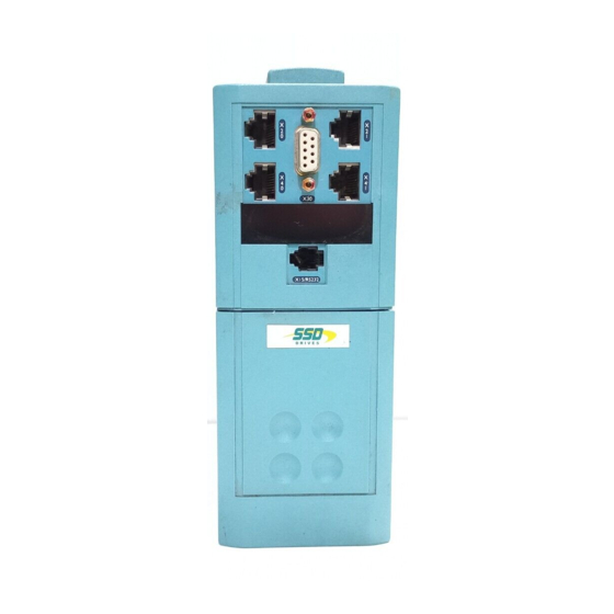
- Page 11 $Q#2YHUYLHZ#RI#WKH#6HUYR#'ULYH## 9(59,(:#2)#7+(# (592# 5,9( &RPSRQHQW#,GHQWLILFDWLRQ X 3 0 X1 5 / R S 2 3 2 Figure 2-1 View of Component Parts 0DLQ#VHUYR#GULYH#DVVHPEO\ < 3RZHU#WHUPLQDO#+;4, 3URGXFW#FRGH#ODEHO ;48256565 6HW0XS#VHUYLFH#FRQQHFWLRQ#+($6<5,'(5#?, 7HUPLQDO#FRYHU &$10%XV#LQSXW#FRQQHFWLRQ 'LDJQRVWLF#GLVSOD\ &$10%XV#RXWSXW#FRQQHFWLRQ (OHFWURQLF#JURXQG#FRQQHFWLRQ 5HVROYHU#FRQQHFWLRQ ([WHUQDO#EUDNH#UHVLVWRU#FRQQHFWLRQ 3XOVH#LQWHUIDFH/#PXOWL0IXQFWLRQ/#LQSXW#FRQQHFWLRQ $GMXVWDEOH#PRXQWLQJ#FOLS 3XOVH#LQWHUIDFH/#PXOWL0IXQFWLRQ/#RXWSXW#FRQQHFWLRQ &RQWURO#WHUPLQDO#+;43, 964#'LJLWDO#6HUYR#'ULYH...
- Page 12 505## $Q#2YHUYLHZ#RI#WKH#6HUYR#'ULYH &RQWURO#)HDWXUHV CAN-Bus terminator CAN-Bus connection to next 631 controller (last controller is terminated) X 3 0 X 3 0 Encoder/Stepper connection to next 631 controller X 15/ RS2 32 X15 /RS 23 Resolver Connection (mandatory) POWER EASYRIDER software...
- Page 13 $Q#2YHUYLHZ#RI#WKH#6HUYR#'ULYH## 631 Servo Drive " Custom-made Software † CAN-Bus current-loop X20/X21 " speed-loop • RS232 EASYRIDER position-loop † PLC I/O ±10V " Instructions Diagnostics Setup Programming Figure 2-2 Communications Options Conventional Control Point-to-Point Synchronisation CAN-Bus Network (analog setpoint value) Position Control...
- Page 14 337# #7$ 339# #9$ 7KUHH#QXPEHUV#VSHFLI\LQJ#WKH#QRPLQDO#LQSXW#YROWDJH#UDWLQJ= 553#WR#5739#+±43(,#83293+] 2QH#FKDUDFWHU#VSHFLI\LQJ#WKH#XVH#RI#WKH#,QWHUQDO#(0),#)LOWHU= )# #)LOWHU 3# #1R#)LOWHU 7ZR#GLJLWV#VSHFLI\LQJ#PHFKDQLFDO#SDFNDJH#LQFOXGLQJ#OLYHU\#DQG#PHFKDQLFDO SDFNDJH#VW\OH/#DQG#DQ\#RSWLRQ#LQVWDOOHG#RYHU#DQG#DERYH#WKH#VWDQGDUG IHDWXUHV#RI#WKH#SURGXFW= (XURWKHUP#6WDQGDUG ([DPSOH 631/002/230/F/00 Servo Drive Type 631 / rated output current 2A / AC supply 230V / with internal filter / Eurotherm standard mechanical package. 964#'LJLWDO#6HUYR#'ULYH...
- Page 15 ,QVWDOOLQJ#WKH#6HUYR#'ULYH## 167$//,1*#7+(# (592# 5,9( ,03257$17=# 5HDG#&KDSWHU#45=#´&HUWLILFDWLRQ#IRU#WKH#6HUYR#'ULYHµ#EHIRUH#LQVWDOOLQJ#WKLV#XQLW1 (0&#,QVWDOODWLRQ#+LQWV $OO#FRPSRQHQWV#DUH#PRXQWHG#RQ#D#PRXQWLQJ#SODWH#+PLQLPXP#WKLFNQHVV 6PP,#LQVLGH#D#VWHHO#FXELFOH1 (QVXUH#JRRG#JURXQGLQJ#RI#WKH#FRPSOHWH#V\VWHP/#LQFOXGLQJ#WKH#JURXQG FRQQHFWLRQV#EHWZHHQ#WKH#FXELFOH#DQG#PDFKLQH1 ,I#PRUH#WKDQ#RQH#PRXQWLQJ#SODWH/#LQWHUFRQQHFW#ZLWK#FRSSHU#UDLOV1 3ODFH#DOO#ZLUHV#DQG#FDEOHV#DV#FORVH#DV#SRVVLEOH#WR#DQ\#JURXQGHG#PHWDO SODQHV1#3RVLWLRQ#FRQWURO#FDEOHV#FORVH#WR#JURXQGHG#PHWDO#SDUWV#ZKHQ H[LWLQJ#WKH#FRQWURO#FXELFOH1 6HSDUDWH#´GLUW\µ/#´FOHDQµ#DQG#´VHQVLWLYHµ#FDEOHV#LI#SRVVLEOH#E\#DW#OHDVW 63PP1#&DEOHV#VKRXOG#FURVV#DW#<3ƒ1 90° $YRLG#FDEOH#ORRSV/#HVSHFLDOO\#EHWZHHQ#WKH#OLQH#ILOWHU#DQG#GULYH#ZKLFK 0,3 m VKRXOG#EH#DV#FORVH#DQG#DV#VKRUW#DV#SRVVLEOH#+GULOOHG,1 2QO\#UHPRYH#WKH#UHTXLUHG#OHQJWK#RI#VFUHHQ#IURP#WKH#HQG#RI#WKH#FDEOH1 8 cm max 0DNH#VFUHHQ#FRQQHFWLRQV#DV#DGYLVHG#LQ#WKLV#PDQXDO1#.HHS#VFUHHQHG FDEOHV#DV#VKRUW#DV#SRVVLEOH/#JURXQG#VFUHHQV#DW#ERWK#HQGV1#)RU#ORQJ FDEOHV/#PDNH#DGGLWLRQDO#VFUHHQHG#FRQQHFWLRQV#DORQJ#WKH#FDEOH#OHQJWK1 &RQQHFW#VFUHHQV#WR#JRRG#TXDOLW\#JURXQGLQJ#SRLQWV1#8VH#80FOLSV#WR#JLYH D#693°#FRQQHFWLRQ1 &RQQHFW#DQ\#XQXVHG#ZLUHV#LQ#WKH#FDEOHV#WR#JURXQG1 8VH#RQO\#(XURWKHUP#ILOWHUV#DQG#FDEOHV#IRU#PRWRU#DQG#UHVROYHU1 5HIHU#WR#&KDSWHU#<=#´$FFHVVRULHVµ 964#'LJLWDO#6HUYR#'ULYH...
- Page 16 Fixing hole centres DIN mounting dimensions SIDE VIEW PANEL MOUNTING VIEW DIN MOUNTING VIEW Figure 3-1 Mechanical Dimensions for 631 964#0RGHO#1XPEHU 964#0RGHO#1XPEHU + + + + : : : : ' ' ' ' )L[LQJV )L[LQJV 964#0RGHO#1XPEHU...
- Page 17 ,QVWDOOLQJ#WKH#6HUYR#'ULYH## 0LQLPXP#$LU#&OHDUDQFHV &XELFOH#6L]H The digital servo drive is protected against damage caused by overheating. There is a thermal sensor installed on the heat sink. When the temperature rises to >95°C, the drive is automatically switched off. This setting cannot be changed. Use a cabinet of the correct size for adequate air circulation, see below.
- Page 18 607## ,QVWDOOLQJ#WKH#6HUYR#'ULYH (OHFWULFDO#,QVWDOODWLRQ ,03257$17=# 3OHDVH#UHDG#WKH#6DIHW\#,QIRUPDWLRQ#RQ#SDJH#&RQW1#6#)#7#EHIRUH#SURFHHGLQJ1 :$51,1*$# (QVXUH#WKDW#DOO#ZLULQJ#LV#HOHFWULFDOO\#LVRODWHG#DQG#FDQQRW#EH#PDGH#´OLYHµ XQLQWHQWLRQDOO\#E\#RWKHU#SHUVRQQHO1 $OO#FRQWURO2UHVROYHU2PRWRU#WKHUPLVWRU#LQSXWV/ L1H#SURWHFWHG#E\#GRXEOH#LQVXODWLRQ#DUH#6(/91 'R#QRW#FRQQHFW#WR#QRQ06(/9#FLUFXLWV1 +5HIHU#WR#&KDSWHU#44=#´7HFKQLFDO#6SHFLILFDWLRQVµ#0#,QVXODWLRQ#&RQFHSW,1 1RWH=# 5HIHU#WR#&KDSWHU#44=#´7HFKQLFDO#6SHFLILFDWLRQVµ#IRU#DGGLWLRQDO#&DEOLQJ#5HTXLUHPHQWV#DQG 7HUPLQDO#%ORFN#:LUH#6L]HV1 ,03257$17=# 7KH#XVH#RI#YDULDEOH#VSHHG#GULYHV#RI#DOO#NLQGV#FDQ#LQYDOLGDWH#WKH#FHUWLILFDWLRQ#IRU#GDQJHURXV DUHDV#+DSSDUDWXV#JURXS#DQG2RU#WHPSHUDWXUH#FODVV,#RI#H[SORVLRQ0SURWHFWHG#PRWRUV1 ,QVSHFWLRQ#DQG#FHUWLILFDWLRQ#IRU#WKH#FRPSOHWH#LQVWDOODWLRQ#RI#VHUYR#PRWRUV#DQG#HOHFWURQLF FRPSRQHQWV#PXVW# PXVW# PXVW# PXVW#EH#REWDLQHG1 EUDNH#UHVLVWRU +LI#UHTXLUHG, +QRLV\, UHVROYHU#FDEOH#+VHQVLWLYH, +QRLV\, +QRLV\, SRZHU VXSSO\ PRWRU PRWRU OLQH FDEOH FDEOH PRWRU FKRNH FKRNH +QRLV\, +RSWLRQDO, +FOHDQ, +LI#UHTXLUHGO,...
- Page 19 Servo Drive” - Solid State Motor Overload Protection. :$51,1*$# 7KH#VHUYR#GULYH#WKHUPLVWRU#FRQQHFWLRQV#DUH#IRU#6(/9#RQO\1 (XURWKHUP#VHUYR#PRWRUV#VHULHV#$&0#5Q/#$&5#Q#DQG#$&*#DUH#6(/9/ RWKHU#PDQXIDFWXUHU·V#PRWRUV#PD\#QRW#EH1 ,I#\RX#XVH#D#QRQ0(XURWKHUP#VHUYR#PRWRU/#PDNH#VXUH#WKDW#WKH#WKHUPLVWRU#LV#LQVXODWHG WR#6(/9#IURP#OLYH#SDUWV#LQVLGH#WKH#PRWRU1#,I#QRW/#WKH#WKHUPLVWRU#VLJQDOV#KDYH#WR#EH#ZLUHG VHSDUDWHO\#DQG#DQ#DGGLWLRQDO#LVRODWLRQ#FLUFXLW#PXVW#EH#SURYLGHG#EHIRUH#FRQQHFWLQJ#WR ;631 0DNH#VXUH#WKDW#SLQV#5#DQG#9#RI#;63#DUH#RQO\#VHUYHG#E\#6(/9#LQVXODWHG#FDEOH#OHDGV1 resolver cable (without thermistor connections) thermistor wires SELV Isolation motor (DUWK#)DXOW#0RQLWRULQJ#6\VWHPV We do not recommend the use of circuit breakers (e.g. RCD, ELCB, GFCI), but where their use is mandatory, they should: •...
- Page 20 EMC filter’s internal capacitors which are connected between phase and earth. This has been minimised in Eurotherm Drives’ filters, but may still trip out any circuit breaker in the earth system. In addition, high frequency and dc components of earth leakage currents will flow under normal operating conditions.
- Page 21 Screen Connections - ensure good connection with conductive surface on the cubicle, remove varnish. Power Servo Motor Figure 3-4 631 Power and Earth Wiring Connections 1RWH=# 7KH#XQLW#PXVW#EH#SHUPDQHQWO\#HDUWKHG#XVLQJ#WZR#LQGHSHQGHQW#HDUWK#FRQGXFWRUV#XVLQJ#;41 3URWHFW#WKH#LQFRPLQJ#PDLQV#VXSSO\#XVLQJ#D#VXLWDEOH#IXVH#RU#FLUFXLW#EUHDNHU#DV#VKRZQ#LQ &KDSWHU#44=#´7HFKQLFDO#6SHFLILFDWLRQVµ#0#3RZHU#'HWDLOV1 0RWRU#&DEOH#&ODPS In order to conform with the specified generic EMC standards, the motor cable must be screened and the screen connected to both the motor frame and the motor cable clamp.
- Page 22 Screen Connections: ensure good connection with conductive surface on the cubicle. Remove varnish. Control Figure 3-5 631 Control Wiring Connections Type Function ANALOG IN, differential to pin 2 ±10V, Ri - 10kΩ referenced to GND ±10V, Ri - 10k Ω...
- Page 23 60< ,QVWDOOLQJ#WKH#6HUYR#'ULYH## 1RWH=# 8VH#VFUHHQHG#FRQWURO#FDEOHV#WR#FRPSO\#ZLWK#(0&#UHTXLUHPHQWV1 All control and signal terminals are SELV, i.e., protected by double/re-inforced insulation. Ensure all wiring is rated for the highest system voltage. Control wiring of between 0.08 mm (28 AWG) - 2.5 mm (14 AWG) can be used. &RQWURO#&DEOH#5HWDLQHU This clip is used to provide guaranteed segregation of the control and power cables.
- Page 24 • position value for position regulation The supplied resolver cable is plugged in to the front of the 631 (socket X30), and into the socket on the Eurotherm approved servo motor. This connection must be made for the 631 to control the operation of the motor.
- Page 25 X40/41 signals are referred to PE Figure 3-8 Application Example To synchronise several 631 servo drives, connect the X40/41 sockets as shown using the specified cables. The 631 is configured using EASYRIDER software The X40/X41 input/output functions are configurable using the EASYRIDER ?#software.
- Page 26 6045## ,QVWDOOLQJ#WKH#6HUYR#'ULYH #0RGH#3#0#,QFUHPHQWDO#2XWSXW#+;732;74, • Incremental encoder simulation for processing in positioning modules • Standard: 1024 increments; other selectable pulse numbers are 512, 256, 128 Encoder Emulation, Incremental OUT based on Resolver Incremental Encoder inputs or outputs conversion )XQFWLRQ )XQFWLRQ )XQFWLRQ )XQFWLRQ ;0SROH#0RGXODU#-DFN/ ($6<5,'(5#?#;73##PRGH# #3...
- Page 27 6046 ,QVWDOOLQJ#WKH#6HUYR#'ULYH## #0RGH#40#,QFUHPHQWDO#,QSXW#+;732;74, Parameter area of the input signals is 10 - 1,000,000 increments Encoder IN Encoder Mode = 1 Incremental IN Incremental Encoder inputs or outputs )XQFWLRQ )XQFWLRQ )XQFWLRQ )XQFWLRQ ;0SROH#0RGXODU#-DFN/ ($6<5,'(5#?#;73##PRGH# #4 ;0SROH#0RGXODU#-DFN/ VFUHHQHG VFUHHQHG ;73#DQG#;74#DUH#LGHQWLFDO#DQG#LQWHUQDOO\#VZLWFKHG LQ#SDUDOOHO1 +;73# #;74,#WKHUHIRUH#ZLULQJ#LV#YHU\#HDV\1 LQWHUQDO#FRQQHFWLRQ#WR &DVH=#6FUHHQHG 4 4 4 4...
- Page 28 6047## ,QVWDOOLQJ#WKH#6HUYR#'ULYH #0RGH#5#0#6WHS0&RQWURO#3XOVH2'LUHFWLRQ#+;732;74, Pulse Stepper Motor Direction Control turn direction (+) turn direction (-) set-up time 2.5µs 2 hold time = 0 Steps in Pulse/Direction Mode = 2 )XQFWLRQ )XQFWLRQ )XQFWLRQ )XQFWLRQ ;0SROH#0RGXODU#-DFN/ ;0SROH#0RGXODU#-DFN/ ($6<5,'(5#?#;73##PRGH# #5 VFUHHQHG VFUHHQHG ;73#DQG#;74#DUH#LGHQWLFDO#DQG#LQWHUQDOO\#VZLWFKHG LQ#SDUDOOHO1 +;73# #;74,#WKHUHIRUH#ZLULQJ#LV#YHU\#HDV\1 LQWHUQDO#FRQQHFWLRQ#WR &DVH=#6FUHHQHG...
- Page 29 6048 ,QVWDOOLQJ#WKH#6HUYR#'ULYH## #0RGH#6#0#6WHS#&RQWURO#3XOVH#+.20,##+;732;74, Stepper pulse direction (+) Motor Control pulse direction (-) Steps In Pulse (+) (-) Mode = 3 )XQFWLRQ ;0SROH#0RGXODU#-DFN/ ($6<5,'(5#?#;73##PRGH# #6 ;0SROH#0RGXODU#-DFN/ VFUHHQHG VFUHHQHG ;73#DQG#;74#DUH#LGHQWLFDO#DQG#LQWHUQDOO\#VZLWFKHG LQ#SDUDOOHO1 +;73# #;74,#WKHUHIRUH#ZLULQJ#LV#YHU\#HDV\1 LQWHUQDO#FRQQHFWLRQ#WR &DVH=#6FUHHQHG 3XOVH#+.,#,QYHUWHG ,1#23. 3XOVH#+., ,1#3 'ULYH#$FWLYH 2XW#5HDG\ 'ULYH#$FWLYH#LQYHUWHG 2XW#25HDG\ 3XOVH#+0, ,1#30...
- Page 30 Termination LAST NODE NODE 1 NODE 2 To network several 631 servo drives, connect the X20/21 sockets as shown using the specified cables. The 631 is configured using EASYRIDER software 1RWH=# 7KH#GDLV\0FKDLQ#ZLULQJ#LV#LQWHQGHG#WR#EH#XVHG#IRU#ORFDO#EXV#GLVWULEXWLRQ1#/RQJ#EXV H[WHQVLRQV#VKRXOG#QRW#FURVV#GDLV\0FKDLQ#VHFWLRQV1 Refer to Chapter 14: “Control and Communications” for cabling details.
-
Page 31: Remote Control
The Operating Mode for the unit is selected using the EASYRIDER software menu: “Commissioning/General”. The 631 unit does not use Modes 0 and 3. If you attempt to select these, the unit will default to the set-up for Mode 1 - speed control. - Page 32 705## 2SHUDWLQJ#0RGHV &RQILJXULQJ#WKH#2372#,QSXWV#DQG#2XWSXWV#+;43, The OPTO Input and Output functions must be configured for use with each Operating Mode. The Input/Output functions for terminals X10.5, X10.6, X10.8, X10.9 and X10.10 are selected in the menu: “Commissioning/Input -Output”. The function of each input/output is determinaed by selecting a number from 0 to 5. The tables below show the possible selections to be used with each Operating Mode.
- Page 33 2SHUDWLQJ#0RGHV## 02'(#7#0#326,7,21#&21752/#+326,7,21#%/2&.6, 02'(#7#0#326,7,21#&21752/#+326,7,21#%/2&.6, 02'(#7#0#326,7,21#&21752/#+326,7,21#%/2&.6, 02'(#7#0#326,7,21#&21752/#+326,7,21#%/2&.6, ($6<5,'(5 ($6<5,'(5 ($6<5,'(5 ($6<5,'(5 'HVFULSWLRQ 'HVFULSWLRQ 'HVFULSWLRQ 'HVFULSWLRQ 7HUPLQDO 7HUPLQDO )XQFWLRQ )XQFWLRQ 7HUPLQDO 7HUPLQDO )XQFWLRQ )XQFWLRQ 2372#RXWSXWV '5,9(#5($'<#+4# #GULYH#FDQ#EH#H[HFXWHG, ,1,7,$/,6('#+4# #PRYH#UHIHUHQFH#H[HFXWHG, 75$,/#&21752/#+4# #SRVLWLRQ#ZLWKLQ#WUDLO#ZLQGRZ, $&7,9(#2.#+4# #SRZHU#VWDJH#DFWLYDWHG, 326,7,21#5($&+('#+4# #SRVLWLRQ#ZLWKLQ#SRVLWLRQ#ZLQGRZ, ,1,7,$/,6('#+4# #PRYH#UHIHUHQFH#H[HFXWHG, 75$,/#&21752/#+4# #SRVLWLRQ#ZLWKLQ#WUDLO#ZLQGRZ, :$51,1*#6,*1$/#+4# #ZDUQLQJ, 2372#LQSXWV )L[HG#LQSXW $&7,9(#0#DFWLYDWHV#PRWRU#SRZHU#ZKHQ#KLJK#DJDLQVW#;4317 5()(5(1&(#6(1625 6752%(#,1387#+VORSH#3#0#!4,#IRU#WKH#%,$6#EORFN...
- Page 34 707## 2SHUDWLQJ#0RGHV 02'(#8#0#326,7,21#&21752/#+%,$6#352*5$0, 02'(#8#0#326,7,21#&21752/#+%,$6#352*5$0, 02'(#8#0#326,7,21#&21752/#+%,$6#352*5$0, 02'(#8#0#326,7,21#&21752/#+%,$6#352*5$0, ($6<5,'(5 ($6<5,'(5 'HVFULSWLRQ 'HVFULSWLRQ ($6<5,'(5 ($6<5,'(5 'HVFULSWLRQ 'HVFULSWLRQ 7HUPLQDO 7HUPLQDO )XQFWLRQ )XQFWLRQ 7HUPLQDO 7HUPLQDO )XQFWLRQ )XQFWLRQ 2372#RXWSXWV '5,9(#5($'<#+4# #GULYH#FDQ#EH#H[HFXWHG, ,1,7,$/,6('#+4# #PRYH#UHIHUHQFH#H[HFXWHG, %,$60287387#8#+VHW2UHVHW#E\#%,$6#SURJUDP, 75$,/#&21752/#+4# #SRVLWLRQ#ZLWKLQ#WUDLO#ZLQGRZ, $&7,9(#2.#+4# #SRZHU#VWDJH#DFWLYDWHG, 326,7,21#5($&+('#+4# #SRVLWLRQ#ZLWKLQ#SRVLWLRQ#ZLQGRZ, ,1,7,$/,6('#+4# #PRYH#UHIHUHQFH#H[HFXWHG, %,$60287387#9#+VHW2UHVHW#E\#%,$6#SURJUDP, 75$,/#&21752/#+4# #SRVLWLRQ#ZLWKLQ#WUDLO#ZLQGRZ, :$51,1*#6,*1$/#+4# #ZDUQLQJ, 2372#LQSXWV )L[HG#LQSXW $&7,9(#0#DFWLYDWHV#PRWRU#SRZHU#ZKHQ#KLJK#DJDLQVW#;4317...
- Page 35 2SHUDWLQJ#0RGHV## )XQFWLRQ#'LDJUDPV#IRU#,QSXWV22XWSXWV Fault signal / Protection mode switching off Protection mode limiting protection function in accordance with EASYRIDER config. menu in accordance with EASYRIDER config. menu regulator protection output Warning(F5) X10.6 output Ready(F0) X10.5 max. current Warning time approx. 3s rated current of regulator Warning display I-LIMIT...
- Page 36 709## 2SHUDWLQJ#0RGHV 0RWRU#2YHUORDG#3URWHFWLRQ This may be detected in two ways: 8VLQJ#7HPSHUDWXUH#6HQVRUV These are located in the motor windings. Enter the relevant data (type, tripping value) in to the EASYRIDER menu: COMMISSIONING / MOTOR / TEMPERATURE SENSOR. ,QWHUQDO#2YHUODRG#3URWHFWLRQ Using thermal simulation of the motor in the drive (I²t), related to the rated current of the motor. Enter the rated current of the motor into the EASYRIDER menu: COMMISSIONING / MOTOR / RATED CURRENT MOTOR.
- Page 37 ,QLWLDO#6HW0XS## 1,7,$/# &RQQHFWLQJ#WKH#;48256565#($6<5,'(5#6HW0XS#6HUYLFH#? ? ? ? Connect your PC to the 631 Servo Drive using the supplied RS232 cable. The cable is wired as shown below. Refer to Chapter 9: “Accessories”. ;48##56565 ;48##56565 ;48##56565 ;48##56565 )XQFWLRQ )XQFWLRQ )XQFWLRQ )XQFWLRQ IRU#3� IRU#3�...
- Page 38 805## ,QLWLDO#6HW0XS 3UH02SHUDWLRQ#&KHFNV :$51,1*$# :DLW#IRU#8#PLQXWHV#DIWHU#GLVFRQQHFWLQJ#SRZHU#EHIRUH#ZRUNLQJ#RQ#DQ\#SDUW#RI#WKH V\VWHP#RU#UHPRYLQJ#WKH#WHUPLQDO#FRYHU#IURP#WKH#6HUYR#'ULYH1 ,QLWLDO#FKHFNV#EHIRUH#DSSO\LQJ#SRZHU= • Mains power supply voltage is correct. • Motor is of correct voltage rating and is connected with the correct polarity. • Check all external wiring circuits - power, control, resolver, motor and earth connections. 1RWH=# &RPSOHWHO\#GLVFRQQHFW#WKH#6HUYR#'ULYH#EHIRUH#SRLQW#WR#SRLQW#FKHFNLQJ#ZLWK#D#EX]]HU/#RU ZKHQ#FKHFNLQJ#LQVXODWLRQ#ZLWK#D#0HJJDU1 •...
- Page 39 ,QLWLDO#6HW0XS## ,QLWDO#6HW0XS#ZLWK#($6<5,'(5#? ? ? ? 1RWH=# 5HIHU#WR#\RXU#($6<5,'(5#VRIWZDUH#+(/3#PHQX1#7KLV#FKDSWHU#SUHVXPHV#\RX#QRZ#KDYH#VRPH H[SHULHQFH#RI#WKH#($6<5,'(5#VRIWZDUH1#,I#QRW/#ZH#VXJJHVW#\RX#SUDFWLFH#LQ#6LPXODWLRQ#0RGH ZLWKLQ#($6<5,'(51 Access to several software functions is password restricted. Commissioning should be carried out by competent personnel only. ,03257$17=# 'XULQJ#FRPPLVVLRQLQJ/#WKH#PRWRU#VKDIW#:,//#URWDWH$ &RPPLVVLRQLQJ#,QVWUXFWLRQV 6WHS $FWLRQ 5HPDUN ,QLWLDO#6HW0XS • 2EVHUYH#DOO#WKH#3UH02SHUDWLRQ#&KHFNV1 • 7KH#GULYH#VKRXOG#EH#IXOO\#DQG#FRUUHFWO\#ZLUHG1#&RQQHFW#WKH#3&#E\#56565#OLQN#WR#WKH#GULYH#VHUYLFH SRUW#;48#DQG#VWDUW#($6<5,'(51 • 6HW#2372#,QSXW#:#WR#EH#127#$&7,9(/#L1H1#;431:#LV#WLHG#ORZ#DJDLQVW#;4316 •...
- Page 40 807## ,QLWLDO#6HW0XS 6WHS $FWLRQ 5HPDUN 7XQLQJ#WKH#3RVLWLRQ#/RRS 6ZLWFK#WKH#SRZHU#2))#DQG#GH0FRXSOH 6ZLWFK#WKH#SRZHU#2))#DQG#GH0FRXSOH 6ZLWFK#WKH#SRZHU#2))#DQG#GH0FRXSOH 6ZLWFK#WKH#SRZHU#2))#DQG#GH0FRXSOH 7KH#ILUVW#VHWXS#RI#WKH#SRVLWLRQLQJ#ORRS#VKRXOG#EH#H[HFXWHG#ZLWK#QR#ORDG1#+:KHQ#WKH#WXQLQJ#LV#ILQLVKHG/#WKH PHFKDQLFV#FDQ#EH#UH0FRQQHFWHG,1 mechanical limits 0RYH#WKH#DSSOLFDWLRQ#WR#D#VDIH#SRVLWLRQ#ZLWKLQ#WKH PHFKDQLFDO#OLPLWV1 6ZLWFK#WKH#SRZHU#21 6ZLWFK#WKH#SRZHU#21 6ZLWFK#WKH#SRZHU#21 6ZLWFK#WKH#SRZHU#21 0DNH#VXUH#\RX#NQRZ#KRZ#WR#VWRS#WKH#PRWRU#LI#QHFHVVDU\ 0DNH#VXUH#\RX#NQRZ#KRZ#WR#VWRS#WKH#PRWRU#LI#QHFHVVDU\ 0DNH#VXUH#\RX#NQRZ#KRZ#WR#VWRS#WKH#PRWRU#LI#QHFHVVDU\ 0DNH#VXUH#\RX#NQRZ#KRZ#WR#VWRS#WKH#PRWRU#LI#QHFHVVDU\ EHIRUH#SHUIRUPLQJ#WKH#IROORZLQJ= EHIRUH#SHUIRUPLQJ#WKH#IROORZLQJ= EHIRUH#SHUIRUPLQJ#WKH#IROORZLQJ= EHIRUH#SHUIRUPLQJ#WKH#IROORZLQJ= Position 1 Position 2 *R#WR#WKH#PHQX#781,1*2326,7,21#/223#781,1*1 $GMXVW#WKH#WHVW#JHQHUDWRU#LQLWLDOO\#WR#VDIH#´9HORFLW\µ/#´$FFHOHUDWLRQµ/#DQG##´'HFHOHUDWLRQµ#YDOXHV1 6HOHFW#VORZ#VSHHG#DQG#VORZ#DFFHOHUDWLRQ2GHFHOHUDWLRQ#ILUVW#WR#LQFUHDVH#ODWHU1 6HOHFW#VDIH#YDOXHV#IRU#´3RVLWLRQ4µ#DQG#´3RVLWLRQ#5µ1 (YHU\#DFWLYDWLRQ#RI#%67$57#0RWRU%#SURGXFHV#D#PRWLRQ#IURP#3RVLWLRQ#4#WR#3RVLWLRQ#5/#DQG#YLFH#YHUVD#ZLWK#WKH QH[W#DFWLYDWLRQ1#6HOHFW#´67$57#0RWRUµ1 2EVHUYH#WKH#EHKDYLRXU#RI#WKH#DSSOLFDWLRQ#DQG#JUDSK#DQG#RSWLPLVH#WKH#WXQLQJ#SDUDPHWHUV#+3/#,#DQG#9#JDLQ,1 ,V#WKH#UHVXOW#RN" <(6 <(6 <(6...
- Page 41 ,QLWLDO#6HW0XS## 7XQLQJ#WKH#&XUUHQW#/RRS ,03257$17=# 2QO\#XQGHUWDNH#WXQLQJ#WKH#FXUUHQW#ORRS#DIWHU#FRQVXOWLQJ#ZLWK#(XURWKHUP#HQJLQHHUV1 6WDEOH#SDUDPHWHUV#DUH#FDOFXODWHG#EDVHG#RQ#WKH#V\VWHP#GDWD#DQG#FDQ#EH#FDOOHG#XS#XVLQJ#WKH#)8#NH\1 0DQXDO#WXQLQJ#PD\#EH#QHFHVVDU\1 5DWHG#YDOXHV#FDQ#EH#VRXUFHG#HLWKHU#GLJLWDOO\#E\#WKH#LQWHUQDO#JHQHUDWRU#RU#DQDORJ#E\#XVLQJ#“439#DW#;4314#DQG ;43151 7KH#DGGLWLRQ#RI#ERWK#VRXUFHV#ZLOO#EH#DFWLYH *R#EDFN#WR#6WHS#7 964#'LJLWDO#6HUYR#'ULYH...
- Page 42 809## ,QLWLDO#6HW0XS 964#'LJLWDO#6HUYR#'ULYH...
- Page 43 285# 33/,&$7,21 ($6<5,'(5#6RIWZDUH The EASYRIDER software tool is provided to fine-tune the 631 servo drive to the motor, and program the servo drive for operation using either “Position Blocks” or the BIAS programming language. Install the software which is available as a DOS version, or suitable for use as a Windows application.
- Page 44 905## 3URJUDPPLQJ#<RXU#$SSOLFDWLRQ Included with these pages are instructions on wiring, safety etc. The Speed Loop and Position Loop Optimization pages will already contain sensible values (loaded from your motor selection) and should require only fine tuning to your system. Having chosen an Operating Mode, you then make relevant selections in the Input/Output Configuration page.
- Page 45 3URJUDPPLQJ#<RXU#$SSOLFDWLRQ## 3/&#)XQFWLRQ The BIAS program can also provide a cyclic PLC function in Operating Mode 5 for supervisory monitoring tasks. This removes the requirement for an external PLC. This is started in parallel to the sequential processing of a BIAS program using the BIAS Execution Pointer command. After the PLC program is activated, the programmed PLC commands are processed as per the specified block number.
- Page 46 907## 3URJUDPPLQJ#<RXU#$SSOLFDWLRQ ($6<5,'(5#0DLQ#6FUHHQ#0#0HQX#2SWLRQV 964#'LJLWDO#6HUYR#'ULYH...
- Page 47 3URJUDPPLQJ#<RXU#$SSOLFDWLRQ## %,$6#&RPPDQGV 964#'LJLWDO#6HUYR#'ULYH...
- Page 48 909## 3URJUDPPLQJ#<RXU#$SSOLFDWLRQ *HQHUDO#.H\ERDUG#'HILQLWLRQV terminate command activate menu system next parameter Shift+Tab previous parameter )XQFWLRQ )XQFWLRQ )XQFWLRQ )XQFWLRQ )XQFWLRQ )XQFWLRQ )XQFWLRQ )XQFWLRQ )XQFWLRQ )XQFWLRQ )XQFWLRQ )XQFWLRQ RQOLQH#KHOS VKLIW.)4 VKLIW.)4 VKLIW.)4 VKLIW.)4 RQOLQH#KHOS FWUO.)4 FWUO.)4 FWUO.)4 FWUO.)4 VKLIW.)5 VKLIW.)5 VKLIW.)5 VKLIW.)5 FWUO.)5 FWUO.)5 FWUO.)5 FWUO.)5...
- Page 49 3URJUDPPLQJ#<RXU#$SSOLFDWLRQ## %,$6#(GLWRU#.H\ERDUG#6KRUWFXWV )XQFWLRQ )XQFWLRQ )XQFWLRQ )XQFWLRQ *HQHUDO#KHOS#VFUHHQ#IRU#WKH#%,$6#(GLWRU 6KLIW.)4 6KLIW.)4 6KLIW.)4 6KLIW.)4 +HOS#ZLWK#WKH#VHOHFWHG#%,$6#FRPPDQG &WUO.)4 &WUO.)4 &WUO.)4 &WUO.)4 +HOS#ZLWK#WKH#DFWXDO#%,$6#EORFN#LQ#SURJUDP /RDG#D#%,$6#SURJUDP#IURP#GLVN 6DYH#WKH#%,$6#SURJUDP#WR#GLVN 7UDQVPLW#WKH#%,$6#SURJUDP $FWLYDWH#WKH#PHQX#OLQH &KDQJH#WR#WKH#QH[W#SDUDPHWHU 6KLIW#.#7DE 6KLIW#.#7DE &KDQJH#WR#WKH#SUHYLRXV#SDUDPHWHU 6KLIW#.#7DE 6KLIW#.#7DE &WUO#.#, &WUO#.#, &WUO#.#, &WUO#.#, &KDQJLQJ#WKH#LQVHUW#PRGH#+WKH#DFWLYH#PRGH#LV#GLVSOD\HG#DW#WKH ERWWRP#RI#WKH#VFUHHQ, &WUO#.#/ &WUO#.#/ &WUO#.#/ &WUO#.#/ ,QVHUWLQJ#D#ODEHO &WUO#.#. &WUO#.#. ,QVHUWLQJ#D#FRPPHQW#OLQH &WUO#.#.
- Page 50 90;## 3URJUDPPLQJ#<RXU#$SSOLFDWLRQ 964#'LJLWDO#6HUYR#'ULYH...
- Page 51 'LDJQRVWLFV#DQG#)DXOW#)LQGLQJ## ,$*1267,&6#$1'# $8/7# ,1',1* The seven-segment display is illuminated when the servo drive is powered-up. It provides information on the state of the drive, active trips, and assists in fault finding. Remember to remove the protective film Diagnostic covering the display when installing the Display drive.
- Page 52 :05## 'LDJQRVWLFV#DQG#)DXOW#)LQGLQJ 'LVSOD\ 'LVSOD\ ([SODQDWLRQ ([SODQDWLRQ 5HDG\#- 5HDG\#- :DUQLQJ#- :DUQLQJ#- &RPPHQW &RPPHQW 'LVSOD\ 'LVSOD\ ([SODQDWLRQ ([SODQDWLRQ 5HDG\#- 5HDG\#- :DUQLQJ#- :DUQLQJ#- &RPPHQW &RPPHQW +RXWSXW#;4318, +RXWSXW#;4319, )DXOW#6XSSO\#XQGHUYROWDJH ,V#WKH#SRZHU#VXSSO\#SUHVHQW" (UURU#VLJQDO#DSSHDUV/#LI#'&0EXV#YROWDJH ?8D#ORZ#WKUHVKROG XQGHU#WKH#8D#ORZ#WKUHVKROG1 )DXOW#LQ#UHVROYHU#V\VWHP ,V#WKH#HQFRGHU#V\VWHP#VXSSO\#SUHVHQW" ,V#WKH#ZLULQJ#WR#WKH#HQFRGHU#V\VWHP RN" ,V#WKH#HQFRGHU#V\VWHP#RN" ,òW#RYHUORDG#RI#WKH#GULYH 'RHV#WKH#FRQWURO#ORRS#RVFLOODWH" 30DPSOLILFDWLRQ#WRR#KLJK 0HFKDQLFV#VWLII" 5HTXLUHPHQWV#WRR#KLJK" ,V#ZDUQLQJ#2;2# HYDOXDWHG"...
- Page 53 'LDJQRVWLFV#DQG#)DXOW#)LQGLQJ## 'LVSOD\ 'LVSOD\ ([SODQDWLRQ ([SODQDWLRQ 5HDG\#- 5HDG\#- :DUQLQJ#- :DUQLQJ#- &RPPHQW &RPPHQW 'LVSOD\ 'LVSOD\ ([SODQDWLRQ ([SODQDWLRQ 5HDG\#- 5HDG\#- :DUQLQJ#- :DUQLQJ#- &RPPHQW &RPPHQW +RXWSXW#;4318, +RXWSXW#;4319, PRWRU#WHPSHUDWXUH#ZDUQLQJ - - - - &KHFN#RYHUORDG#RI#WKH#PRWRU2FRROLQJ HWF1 EDOODVW#DFWLYH %UDNH#YLJRXU#LV#UHPRYHG ZDUQLQJ#EDOODVW - - - - %DOODVW#UHVLVWDQFH#XVDJH#LV#!<3( VZLWFK#RII#EDOODVW - - - - %DOODVW#UHVLVWDQFH#RYHUORDGHG WUDLOLQJ#ZLQGRZ#H[FHHGHG 2QO\#LQ#RSHUDWLRQ#PRGH#%SRVLWLRQ...
-
Page 54: Drive Status
:07## 'LDJQRVWLFV#DQG#)DXOW#)LQGLQJ )DXOW#)LQGLQJ The following list refers to faults which can occur during operation. (UURU (UURU (UURU (UURU ([SODQDWLRQ#DQG#UHPHG\ ([SODQDWLRQ#DQG#UHPHG\ ([SODQDWLRQ#DQG#UHPHG\ ([SODQDWLRQ#DQG#UHPHG\ - - - - 0RWRU#GRHV#QRW#RSHUDWH#GHVSLWH#FXUUHQW#IORZ ,V#WKH#PRWRU#PHFKDQLFDOO\#EORFNHG" ,V#WKH#PRWRU#EUDNH#UHOHDVHG" 0RWRU#UXQV#XQHYHQO\ &KHFN#WKH#VHWSRLQW#ZLULQJ1#&KHFN#JURXQGLQJ#DQG#VKLHOGLQJ1 ,QDSSURSULDWH#VSHHG#ORRS#YDOXHV#" • 5HGXFH#DPSOLILFDWLRQ#DQG2RU#LQFUHDVH#WLPH#FRQVWDQW#+XVH ($6<5,'(5, 1R#UHDFWLRQ#RQ#VHWSRLQW#YDOXH#DOWKRXJK /LPLW#VZLWFK#0#IXQFWLRQV#DFWLYDWHG#"#+%,$6, WRUTXH#LQ#VWDQG#VWLOO 1R#FXUUHQW#IORZ>#QR#WRUTXH#GHVSLWH#DFWLYDWLQJ 0RWRU#FDEOHV#LQWHUUXSWHG" WKH#UHJXODWRU#FRUUHFWO\ ,QWHUIHUHQFH#V\PSWRPV#ZLWK#SRZHU#IUHTXHQF\ *URXQG#ORRSV#LQ#VHWSRLQW#RU#DFWXDO#YDOXH#ZLULQJ"... - Page 55 'LDJQRVWLFV#DQG#)DXOW#)LQGLQJ## +LVWRU\#6WDWXV#0HPRU\ When the unit is powered down, a set of important indicators is stored in to dedicated memory. This allows the last eight status conditions to displayed by the EASYRIDER diagnostic menu Thus important failure information, for instance, is not lost when the unit is powered down. 964#'LJLWDO#6HUYR#'ULYH...
- Page 56 :09## 'LDJQRVWLFV#DQG#)DXOW#)LQGLQJ 964#'LJLWDO#6HUYR#'ULYH...
- Page 57 • Details of the fault Contact your nearest Eurotherm Drives Service Centre to arrange return of the item. You will be given a Returned Material Authorisation. Use this as a reference on all paperwork you return with the faulty item. Pack and despatch the item in the original packing materials; or at least an anti-static enclosure.
- Page 58 ;05## 5RXWLQH#0DLQWHQDQFH#DQG#5HSDLU 964#'LJLWDO#6HUYR#'ULYH...
- Page 59 <04 $FFHVVRULHV## &&(6625,(6 < # 1RWH=# 2WKHU#FDEOH#OHQJWKV#DUH#DYDLODEOH/#FRQWDFW#(XURWKHUP#'ULYHV#IRU#GHWDLOV1 3URGXFWV 3URGXFWV 3URGXFWV 3URGXFWV 2UGHU#1XPEHU 2UGHU#1XPEHU 2UGHU#1XPEHU 2UGHU#1XPEHU ,OOXVWUDWLRQ ,OOXVWUDWLRQ ,OOXVWUDWLRQ ,OOXVWUDWLRQ 0RWRU#&DEOH 0RWRU#&DEOH 0RWRU#&DEOH 0RWRU#&DEOH &079<3548353 )RU#$&*#PRWRUV#RQO\ /RZ0FRVW#FDEOH#IRU#IL[HG#LQVWDOODWLRQV#RQO\ 0#ZLWKRXW#+ROGLQJ#%UDNH#ZLUHV 0RWRU#&DEOH 0RWRU#&DEOH 0RWRU#&DEOH 0RWRU#&DEOH &079<3568353 )RU#$&*/#$Q#DQG#$Q#PRWRUV )OH[LEOH#FDEOH#0#ZLWK#KROGLQJ#EUDNH#ZLUHV 5HVROYHU#&DEOH 5HVROYHU#&DEOH &079<3588353 5HVROYHU#&DEOH 5HVROYHU#&DEOH Sub-miniature D, 9 way )RU#$&*/#$Q#DQG#$Q#PRWRUV +;63, /RZ0FRVW#FDEOH#IRU#IL[HG#LQVWDOODWLRQV#RQO\...
- Page 60 <05## $FFHVVRULHV &DEOH#IRU#+RVW#8QLWV &DEOH#IRU#+RVW#8QLWV &DEOH#IRU#+RVW#8QLWV &DEOH#IRU#+RVW#8QLWV &079<3668343 Round cable, RJ45 Plug 8 way 4TP, shielded ;73274#+0XOWL0IXQFWLRQ, pairs 7#WZLVWHG#SDLUV/#VKLHOGHG#FDEOH XQWHUPLQDWHG#DW#WKH#IUHH0HQG $GDSWRU#&DEOH $GDSWRU#&DEOH $GDSWRU#&DEOH $GDSWRU#&DEOH &079<3678336 RJ45 Plug 8 way Sub-miniature D, 9 way female 964#;73274#WR#968296:#;73 pairs +0XOWL0IXQFWLRQ, 300 mm 7#WZLVWHG#SDLUV/#VKLHOGHG#FDEOH %UDNH#5HVLVWRU %UDNH#5HVLVWRU &=79<34<...
- Page 61 4304 5HIHUHQFH#7DEOHV## ()(5(1&(# $%/(6 4 3 # $6&,,#7DEOH %,1$5< '& '& ´ '& & & '& $&. 6<1 ¶ &$1 < < < (6& > > & &5 " 964#'LJLWDO#6HUYR#'ULYH...
- Page 62 4305## 5HIHUHQFH#7DEOHV 'HFLPDO2+H[DGHFLPDO#7DEOH 3 3 3 3 4 4 4 4 5 5 5 5 6 6 6 6 7 7 7 7 8 8 8 8 9 9 9 9 : : : : ; ; ; ; < < < < 3 3 3 3 3333 3334...
- Page 63 4306 5HIHUHQFH#7DEOHV## 'HFLPDO2+H[DGHFLPDO#7DEOH 3 3 3 3 4 4 4 4 5 5 5 5 6 6 6 6 7 7 7 7 8 8 8 8 9 9 9 9 : : : : ; ; ; ; < < < < 34)7 34)8 34)9...
- Page 64 4307## 5HIHUHQFH#7DEOHV 964#'LJLWDO#6HUYR#'ULYH...
- Page 65 4404 7HFKQLFDO#6SHFLILFDWLRQV## (&+1,&$/# 3(&,),&$7,216 4 4 # *HQHUDO#'DWD (QYLURQPHQWDO#'HWDLOV The unit MUST be mounted inside a suitable cubicle. 2SHUDWLQJ#7HPSHUDWXUH 2SHUDWLQJ#7HPSHUDWXUH 2SHUDWLQJ#7HPSHUDWXUH 2SHUDWLQJ#7HPSHUDWXUH 3°&#WR#73°&#+GHUDWH#WKH#RXWSXW#FXUUHQW#E\#5(#SHU#°&#EHWZHHQ#73083°& 2SHUDWLQJ#WHPSHUDWXUH#LV#GHILQHG#DV#WKH#DPELHQW#WHPSHUDWXUH#WR#WKH#LPPHGLDWH#VXUURXQG#RI#WKH 6HUYR#'ULYH/#ZKHQ#WKH#6HUYR#'ULYH#DQG#RWKHU#HTXLSPHQW#DGMDFHQW#WR#LW#LV#RSHUDWLQJ#DW#ZRUVW#FDVH FRQGLWLRQV1 6WRUDJH#7HPSHUDWXUH 6WRUDJH#7HPSHUDWXUH 6WRUDJH#7HPSHUDWXUH 6WRUDJH#7HPSHUDWXUH 058°&#WR#.88°& 6KLSSLQJ#7HPSHUDWXUH 6KLSSLQJ#7HPSHUDWXUH 6KLSSLQJ#7HPSHUDWXUH 6KLSSLQJ#7HPSHUDWXUH 058°&#WR#.:3#°& 3URGXFW#(QFORVXUH#5DWLQJ 3URGXFW#(QFORVXUH#5DWLQJ 3URGXFW#(QFORVXUH#5DWLQJ 3URGXFW#(QFORVXUH#5DWLQJ &XELFOH#0RXQWHG ,353 9LEUDWLRQ#7HVW...
- Page 66 4405## 7HFKQLFDO#6SHFLILFDWLRQV &DEOLQJ#5HTXLUHPHQWV#IRU#(0&#&RPSOLDQFH * For cable lengths longer than 15 and up to 50 metres contact Eurotherm Drives. 5HVROYHU 5HVROYHU 5HVROYHU 5HVROYHU 3RZHU#6XSSO\#&DEOH 3RZHU#6XSSO\#&DEOH 3RZHU#6XSSO\#&DEOH 3RZHU#6XSSO\#&DEOH 0RWRU#&DEOH 0RWRU#&DEOH 0RWRU#&DEOH 0RWRU#&DEOH %UDNH#5HVLVWRU#&DEOH %UDNH#5HVLVWRU#&DEOH %UDNH#5HVLVWRU#&DEOH %UDNH#5HVLVWRU#&DEOH 6LJQDO2&RQWURO#&DEOH 6LJQDO2&RQWURO#&DEOH 6LJQDO2&RQWURO#&DEOH 6LJQDO2&RQWURO#&DEOH &DEOH#7\SH &DEOH#7\SH...
- Page 67 4406 7HFKQLFDO#6SHFLILFDWLRQV## (DUWKLQJ26DIHW\#'HWDLOV Refer to Chapter 12 : “Certification for the Servo Drive”. (DUWKLQJ (DUWKLQJ 3HUPDQHQW#HDUWKLQJ#LV#PDQGDWRU\#RQ#DOO#XQLWV1 (DUWKLQJ (DUWKLQJ • 8VH#D#FRSSHU#SURWHFWLYH#HDUWK#FRQGXFWRU#43PPò#PLQLPXP#FURVV0VHFWLRQ/#RU#LQVWDOO#D#VHFRQG FRQGXFWRU#LQ#SDUDOOHO#ZLWK#WKH#SURWHFWLYH#FRQGXFWRU#WR#D#VHSDUDWH#SURWHFWLYH#HDUWK#WHUPLQDO • 7KH#FRQGXFWRU#LWVHOI#PXVW#PHHW#ORFDO#UHTXLUHPHQWV#IRU#D#SURWHFWLYH#HDUWK#FRQGXFWRU ,QSXW#6XSSO\#'HWDLOV ,QSXW#6XSSO\#'HWDLOV 8QLWV#ZLWK#WKH#LQWHUQDO#ILOWHU#DUH#RQO\#VXLWDEOH#IRU#XVH#RQ#HDUWK#UHIHUHQFHG#VXSSOLHV#+71,1 ,QSXW#6XSSO\#'HWDLOV ,QSXW#6XSSO\#'HWDLOV +71,#DQG#+,7, +71,#DQG#+,7, +71,#DQG#+,7, +71,#DQG#+,7, 8QLWV#ZLWKRXW#WKH#ILOWHU#DUH#VXLWDEOH#IRU#HDUWK#+71,#RU#QRQ0HDUWK#UHIHUHQFHG#+,7,#VXSSOLHV1 3RZHU#&LUFXLW (OHFWULFDO#VHSDUDWLRQ#IURP#FRQWURO#FLUFXLW (OHFWULFDO#VHSDUDWLRQ#IURP#FRQWURO#FLUFXLW ,Q#DFFRUGDQFH#ZLWK#9'(#3493#2#(1#834:;#RU#8/83;& (OHFWULFDO#VHSDUDWLRQ#IURP#FRQWURO#FLUFXLW (OHFWULFDO#VHSDUDWLRQ#IURP#FRQWURO#FLUFXLW 6KRUW0FLUFXLW#DQG#WR#IUDPH#SURRI#IRU 6KRUW0FLUFXLW#DQG#WR#IUDPH#SURRI#IRU 6KRUW0FLUFXLW#DQG#WR#IUDPH#SURRI#IRU 6KRUW0FLUFXLW#DQG#WR#IUDPH#SURRI#IRU...
- Page 68 4407## 7HFKQLFDO#6SHFLILFDWLRQV 5HVROYHU#&RQYHUVLRQ#+;63, The specified data refers to the standard resolver interface, operated with the Eurotherm Resolver R 21-T05, R15-T05. &DUULHU#IUHTXHQF\ &DUULHU#IUHTXHQF\ I W # #71:8N+] &DUULHU#IUHTXHQF\ &DUULHU#IUHTXHQF\ /LQHDULW\#HUURU#RI#WKH#DFWXDO#YDOXH#VLJQDO /LQHDULW\#HUURU#RI#WKH#DFWXDO#YDOXH#VLJQDO /LQHDULW\#HUURU#RI#WKH#DFWXDO#YDOXH#VLJQDO /LQHDULW\#HUURU#RI#WKH#DFWXDO#YDOXH#VLJQDO 4( 5LSSOH#RI#WKH#DFWXDO#YDOXH#VLJQDO 5LSSOH#RI#WKH#DFWXDO#YDOXH#VLJQDO 5LSSOH#RI#WKH#DFWXDO#YDOXH#VLJQDO 5LSSOH#RI#WKH#DFWXDO#YDOXH#VLJQDO 0D[LPXP#SRVLWLRQ#UHVROXWLRQ#IRU#RQH 0D[LPXP#SRVLWLRQ#UHVROXWLRQ#IRU#RQH 496;7#LQFUHPHQWV/#47#ELW 0D[LPXP#SRVLWLRQ#UHVROXWLRQ#IRU#RQH 0D[LPXP#SRVLWLRQ#UHVROXWLRQ#IRU#RQH UHYROXWLRQ...
- Page 69 4408 7HFKQLFDO#6SHFLILFDWLRQV## 'LJLWDO#&RQWURO &XUUHQW#&RQWURO &XUUHQW#&RQWURO &XUUHQW#&RQWURO &XUUHQW#&RQWURO 6HWWLQJV 6HWWLQJV $FFRUGLQJ#WR#IDFWRU\#VSHFLILFDWLRQV#RU#PRWRU#GDWD 6HWWLQJV 6HWWLQJV &XUUHQW#/LPLWV &XUUHQW#/LPLWV &XUUHQW#/LPLWV &XUUHQW#/LPLWV 6HW#E\#WKH#3DUDPHWHU#0HQX 6SHHG#&RQWURO 6SHHG#&RQWURO 6SHHG#&RQWURO 6SHHG#&RQWURO 6HWWLQJV 6HWWLQJV 6HW#E\#WKH#3DUDPHWHU#0HQX 6HWWLQJV 6HWWLQJV 'LIIHUHQWLDO#6HWSRLQW#,QSXW#$QDORJ 'LIIHUHQWLDO#6HWSRLQW#,QSXW#$QDORJ 'LIIHUHQWLDO#6HWSRLQW#,QSXW#$QDORJ 'LIIHUHQWLDO#6HWSRLQW#,QSXW#$QDORJ # #439/#FDQ#EH#QRUPHG>#5 L # #43N VROO 5HVROXWLRQ#+LQFOXGLQJ#VLJQ, 5HVROXWLRQ#+LQFOXGLQJ#VLJQ, 5HVROXWLRQ#+LQFOXGLQJ#VLJQ, 5HVROXWLRQ#+LQFOXGLQJ#VLJQ, 45#ELW 'LJLWDO#6HWSRLQW#,QSXW 'LJLWDO#6HWSRLQW#,QSXW...
- Page 70 4409## 7HFKQLFDO#6SHFLILFDWLRQV 3URGXFW#6SHFLILF#'DWD ,03257$17=# 0RWRU#SRZHU/#RXWSXW#FXUUHQW#DQG#LQSXW#FXUUHQW#PXVW#QRW#EH#H[FHHGHG#XQGHU#VWHDG\#VWDWH RSHUDWLQJ#FRQGLWLRQV1 # 9 64#3URGXFW#&RGH#0#EORFN#5 964#3URGXFW#&RGH#0#EORFN#5 # # # # 3 34 # # # # 3 35 # # # # 3 37 # # # # 3 39 964#3URGXFW#&RGH#0#EORFN#5 964#3URGXFW#&RGH#0#EORFN#5 (0&#&RPSOLDQFH # All models (XURSHDQ#&RPPXQLW\#'LUHFWLYH#;<26692((&...
- Page 71 4504 &HUWLILFDWLRQ#IRU#WKH#6HUYR#'ULYH## & (57,),&$7,21#)25#7+(# (592# 5,9( 4 5 # 5HTXLUHPHQWV#IRU#(0&#&RPSOLDQFH All Variable Speed Drives (VSDs) potentially produce electrical emissions which are radiated into the environment and conducted back into the ac supply. VSDs are inherently immune to any additional external electrical noise. The following information is provided to maximise the Electro Magnetic Compatibility (EMC) of VSDs and systems in their intended operating environment, by minimising their emissions and maximising their immunity.
- Page 72 4505## &HUWLILFDWLRQ#IRU#WKH#6HUYR#'ULYH Control and signal cables for the encoder and all analog inputs normally require screening with the screen connected only at the VSD end. However, if high frequency noise is still a problem, earth screen at the non VSD end via a 0.1µF capacitor. 1RWH=# &RQQHFW#WKH#VFUHHQ#+DW#WKH#96'#HQG,#WR#WKH#96'#SURWHFWLYH#HDUWK#SRLQW/#DQG#QRW#WR#WKH FRQWURO#ERDUG#WHUPLQDOV1 &DEOLQJ#5HTXLUHPHQWV...
- Page 73 4506 &HUWLILFDWLRQ#IRU#WKH#6HUYR#'ULYH## 1RWH=# 5DGLDWHG#PDJQHWLF#DQG#HOHFWULF#ILHOGV#LQVLGH#WKH#FXELFOH#PD\#EH#KLJK#DQG#DQ\#FRPSRQHQWV ILWWHG#LQVLGH#PXVW#EH#VXIILFLHQWO\#LPPXQH1 The VSD and associated equipment are mounted onto a conducting, metal mounting panel. Do not use cubicle constructions that use insulating mounting panels or undefined mounting structures. Cables between the VSD and motor must be screened or armoured and terminated at the entrance to the cubicle.
- Page 74 4507## &HUWLILFDWLRQ#IRU#WKH#6HUYR#'ULYH incoming safety earth from the main supply. Flexible, large cross-section cable is used to ensure a low HF impedance. Busbars are arranged so that connection to the single earth point is as short as possible. 4#&OHDQ#(DUWK#%XVEDU#+LQVXODWHG#IURP#WKH#PRXQWLQJ#SDQHO, Used as a reference point for all signal and control cabling. This may be further subdivided into an analog and a digital reference busbar, each separately connected to the star earthing point.
- Page 75 4508 &HUWLILFDWLRQ#IRU#WKH#6HUYR#'ULYH## 6HQVLWLYH#(TXLSPHQW The proximity of the source and victim circuit has a large effect on radiated coupling. The electromagnetic fields produced by VSDs falls off rapidly with distance from the cabling/cubicle. Remember that the radiated fields from EMC compliant drive systems are measured at least 10m from the equipment, over the band 30-1000MHz.
- Page 76 4509## &HUWLILFDWLRQ#IRU#WKH#6HUYR#'ULYH 5HTXLUHPHQWV#IRU#8/#&RPSOLDQFH 6ROLG06WDWH#0RWRU#2YHUORDG#3URWHFWLRQ These devices provide Class 10 motor overload protection. The maximum internal overload protection level (current limit) is 200% for 5 seconds. An external motor overload protective device must be provided by the installer where the motor has a full-load ampere rating of less than 40% of the drive output rating.
- Page 77 Directive. &(#0DUNLQJ#IRU#/RZ#9ROWDJH#'LUHFWLYH When installed in accordance with this manual, the 631 Servo Drive is CE marked by Eurotherm Drives Ltd in accordance with the low voltage directive (S.I. No. 3260 implements this LVD directive into UK law). An EC Declaration of Conformity (low voltage directive) is included at the end of this chapter.
- Page 78 450;## &HUWLILFDWLRQ#IRU#WKH#6HUYR#'ULYH #(XURWKHUP#'ULYHV#5HVSRQVLELOLW\ You intend to use the unit as relevant apparatus. When the unit is factory-fitted with the internal EMC filter and installed following EMC installation instructions, it complies with the relevant standards indicated in the following tables. The relevant declarations are to be found at the end of this chapter. The CE mark is displayed on the EC Declaration of Conformity (EMC Directive) provided at the end of this chapter.
- Page 79 450< &HUWLILFDWLRQ#IRU#WKH#6HUYR#'ULYH## Conformance can be demonstrated using the Generic Standards or the Product Specific Standard. The following tables indicate, for the two methods of compliance, the standards that the unit may comply with if installed and used correctly. 8QLW#XVHG#DV 8QLW#XVHG#DV 8QLW#XVHG#DV 8QLW#XVHG#DV 8QLW#XVHG#DV#D...
- Page 80 45043## &HUWLILFDWLRQ#IRU#WKH#6HUYR#'ULYH 8QLW#XVHG#DV 8QLW#XVHG#DV 8QLW#XVHG#DV#D 8QLW#XVHG#DV#D 8QLW#XVHG#DV 8QLW#XVHG#DV 8QLW#XVHG#DV#D 8QLW#XVHG#DV#D 3URGXFW#6SHFLILF#6WDQGDUG#(194;3306 5HOHYDQW#$SSDUDWXV 5HOHYDQW#$SSDUDWXV 5HOHYDQW#$SSDUDWXV 5HOHYDQW#$SSDUDWXV &RPSRQHQW &RPSRQHQW &RPSRQHQW &RPSRQHQW ILOWHU ILOWHU $VVXPLQJ#LQVWDOODWLRQ#WR#(0&#LQVWUXFWLRQV#LQ#WKLV#PDQXDO QR#ILOWHU QR#ILOWHU +(0& +(0& ´)LOWHUµ#UHIHUV#WR#WKH#IDFWRU\0ILWWHG#LQWHUQDO#ILOWHU1 FRPSOLDQFH, FRPSOLDQFH PD\#EH DSSOLHG#IRU, ,QVWDOODWLRQ ,QVWDOODWLRQ ,QVWDOODWLRQ ,QVWDOODWLRQ 6DOHV 6DOHV 6DOHV 6DOHV 3HUIRUPDQFH#5HTXLUHG 3HUIRUPDQFH#5HTXLUHG 3HUIRUPDQFH#5HTXLUHG 3HUIRUPDQFH#5HTXLUHG...
- Page 81 OR THE PRODUCT SPECIFIC STANDARD NO EMC 'CE' MARK APPLIED TO E.D. MODULE. EN50081-2(1994) AND EN50082-1(1998) AND EN50082-2(1995), EN61800-3 (1996) E.D. = EUROTHERM DRIVES LIMITED RELEVANT APPARATUS CEMEP : Refer to Chapter 12, "European Directives and the CE Mark" MANUFACTURER/SUPPLIER/INSTALLERS RESPONSIBILITY TO CONFORM WITH EMC DIRECTIVE.
- Page 82 In accordance with the EEC Directive 89/336/EEC, Article 10 and Annex 1, (EMC DIRECTIVE) We Eurotherm Drives Limited, address as below, declare under our sole responsibility that the following Electronic Products When installed and operated with reference to the instructions in the Product Manual...
- Page 83 In accordance with the EEC Directive 89/336/EEC, Article 10 and Annex 1, (EMC DIRECTIVE) We Eurotherm Drives Ltd., address as below, declare under our sole responsibility that the following electronic products When installed, used and CE marked in accordance with the instructions in the Product Manual...
- Page 84 45047## &HUWLILFDWLRQ#IRU#WKH#6HUYR#'ULYH (&#'HFODUDWLRQ#RI#&RQIRUPLW\#+/RZ#9ROWDJH#'LUHFWLYH, The 631 Servo Drive is CE marked in accordance with the low voltage directive for electrical equipment and appliances in the voltage range 50-1000V ac and 75-1500V dc when installed correctly. (8527+(50 '5,9(6 (&#'(&/$5$7,21#2)#&21)250,7< In accordance with the EEC Directive 73/23/EEC and amended by 93/68/EEC,...
- Page 85 &HUWLILFDWLRQ#IRU#WKH#6HUYR#'ULYH## 0DQXIDFWXUHU·V#'HFODUDWLRQ Since the potential hazards are mainly electrical rather than mechanical, the 631 Servo Drive does not fall under the machinery directive. However, we do supply a manufacturer’s declaration for when the 631 Servo Drive is used (as a component) in machinery.
- Page 86 45049## &HUWLILFDWLRQ#IRU#WKH#6HUYR#'ULYH 964#'LJLWDO#6HUYR#'ULYH...
- Page 87 Resolver. 8VLQJ#/LQH#&KRNHV Line chokes are not required to limit input current to Eurotherm Drives Servo drives. Line chokes may be used to reduce the harmonic content of the supply current where this a particular requirement of the application or where greater protection from mains borne transients is required.
- Page 88 4605## $SSOLFDWLRQ#1RWHV '\QDPLF#%UDNLQJ The energy of a moving system flows back into the drive while decelerating. The DC-Bus capacitors are able to take a small value. The remainder is converted to heat by a high power resistor switched across the DC link. Switching on and off of this brake resistor depends on the DC-Bus voltage.
- Page 89 Due to the line-ripple of DC Bus, the rate of usable output voltage is derated as follows. This deration affects the maximum achievable speed of the applied motor. Output current (A) 1-ph 50 Hz * 1-ph 50 Hz * 631/006 631/004.006 Limit for continuous operation >1 minute 1-ph 50Hz * 631/001.002...
- Page 90 4607## $SSOLFDWLRQ#1RWHV Approximate calculation of required motor terminal voltage for a specified motor speed (up to 3000rpm) Ukl = 1,2 (EMC*n/1000 + I* (Rph + RL) (Volts) where: Required motor voltage (V rms) Back-EMF of motor (V rms)/1000 rpm Resistance of motor (between terminals) (Ω) Line resistance of motor cable (Ω) Motor-current (A rms) 964#'LJLWDO#6HUYR#'ULYH...
- Page 91 4704 )XQFWLRQDO#%ORFN#'LDJUDP## 81&7,21$/# /2&.# ,$*5$0 4 7 # Current Limit Configurable Functions (Limit Switches etc.) Supervising Setpoint Processing Speed+ Speed- Speed Loop Nsoll A/D Converter Analog Input Nsoll Speed Demand IQsoll Current Demand SELV Isolation IQsoll Current Demand VDE 0884 VDE 0160 / EN50178 MOTOR Current Loop IGBT...
- Page 92 4705## )XQFWLRQDO#%ORFN#'LDJUDP 964#'LJLWDO#6HUYR#'ULYH...
- Page 93 ECN No. DATE DRAWN CHK'D ISS. MODIFICATION 3UHOLPLQDU\#LVVXH#RQO\ 45:<7 ;292<< &0 'LJLWDOO\#SULQWHG1#1HZ#($6<5,'(5#LQIRUPDWLRQ1 45:<7 48292<< &0 ),567#86('#21 02',),&$7,21#5(&25' 964#'LJLWDO#6HUYR#'ULYH '5$:,1*#180%(5 6+71#4 (8527+(50#'5,9(6 ==79<3498334 2)##4...
Need help?
Do you have a question about the 631 and is the answer not in the manual?
Questions and answers