Advertisement
Quick Links
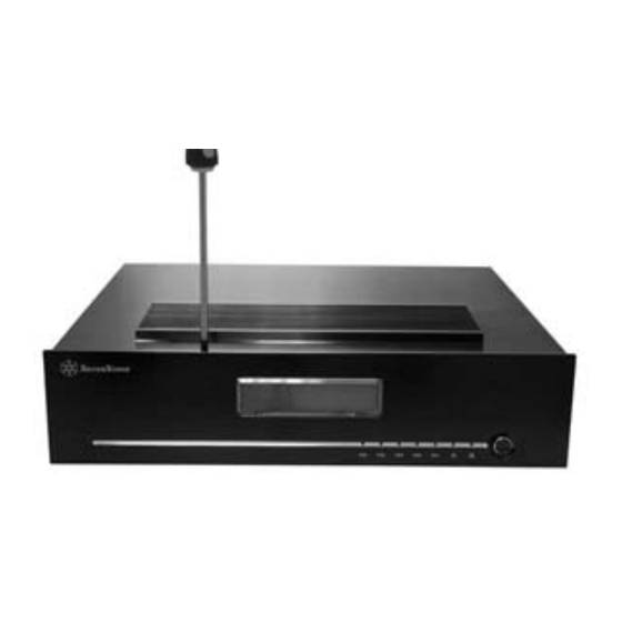
1. DS351 Installation
1. Take DS351 and accessory packet out of the box.
2. Take out the contents of accessory packet and make sure there is a, manual,
CD, PCIE to E-SATA card, SATA cable x 5pcs, Power cord, screw packet, and
cable management bands.
3. Loosen total 9 screws: two on the top panel, four on the left and right side,
and three on the back.
Advertisement

Subscribe to Our Youtube Channel
Related Manuals for SilverStone DS351


Summary of Contents for SilverStone DS351
- Page 1 1. DS351 Installation 1. Take DS351 and accessory packet out of the box. 2. Take out the contents of accessory packet and make sure there is a, manual, CD, PCIE to E-SATA card, SATA cable x 5pcs, Power cord, screw packet, and cable management bands.
- Page 2 4. The top panel then can be taken off easily. 5. Loosen the 6 screws on the hard disk bracket and remove the screws. 6. Lift to take out hard disk bracket.
- Page 3 7. Install hard disk into the bracket. 8. Tighten and secure the hard disk in the bracket. 9. Take out the temperature sensor behind the front panel.
- Page 4 10. Remove the protective layer from the temperature sensor. 11. Use a piece of tape and tape the tip of the temperature sensor to the surface of the hard disk (Caution! Do not tape the temperature sensor to the circuit board or on the chip itself) 12.
- Page 5 13. Install the hard disk in the bracket. 14. After installing all 4 hard disks, install the bracket in the chassis. 15. Loosen and take out the hard disk bracket located in the rear of the chassis.
- Page 6 16. Fasten and secure the hard disk on the bracket. 17. Then place and secure the bracket with hard disk installed in the chassis. 18. Again place the tip of temperature sensor on the hard disk.
- Page 7 19. Take out the SATA power cord from the accessory pack. 20. Connect the end with SATA and power cord to the hard disk. 21. Connect the power cord end to the power supply.
- Page 8 22. Connect the SATA cable end to the circuit board. 23. Repeat the above 3 process until all 5 hard disks are installed. 24. Use the cable management strap in the chassis to organize all the cables.
- Page 9 25. If you have your own 80mm cooling fans, you can install the fans as pictured. 26. Connect the power cable from the fan to the power cable from the front panel. 27. Place the top panel back on the chassis.
- Page 10 28. Tighten and secure top panel with screws. 2. Connect the DS351 to the computer 1. TYPE1: When E-SATA motherboard uses SiI3132 chip. 2. Directly connect E-SATA connector to the E-SATA slot located behind the...
- Page 11 motherboard. 3. Please take out the PCI Express card if there is no SiI3132 chip on your motherboard. 4. TYPE2 motherboard: When there are sufficient PCI Express-X1 slots.
- Page 12 5. Insert the PCI Express card into one of the circled slots in the picture. 6. TYPE3 motherboard : When there is no PCI Express-X1 slot available, but there is PCI Express-X4 available.
- Page 13 7. Install the PCI Express card on slot circled in the previous picture. 8. TYPE4 motherboard : When there are only PCI Express-X8 or PCI Express-X16 slots available. 9. Insert the PCI Express card into one of the circled slots in the previous step.
- Page 14 10. First connect the one end of E-SATA connector to the E-SATA slot as pictured. 11. Then connect the other end to the back of the DS351. 12. Picture when power is off.
- Page 15 13. Picture when power is on.
Need help?
Do you have a question about the DS351 and is the answer not in the manual?
Questions and answers