Table of Contents
Advertisement
Quick Links
GE Power Management
215 Anderson Avenue, Markham, Ontario
Canada L6E 1B3
Tel: (905) 294-6222 Fax: (905) 201-2098
Internet: http://www.GEindustrial.com/pm
FEEDER PROTECTION RELAY
INSTRUCTION MANUAL
Manual P/N: 1601-0048-DE (GEK-106291A)
STATUS
TRIP
COMMUNICATION
1
TIME 51
INST 50
RELAY IN
2
A
3
SERVICE
4
SERVICE
5
B
6
REQUIRED
7
8
PHASE
C
PICKUP
GROUND
G
PICKUP
CLEAR
PHASE
PICKUP
CURVE SHAPE
TIME MULTIPLIER
(% OF CT)
150
60
OFF
OFF
GROUND
PICKUP
CURVE SHAPE
TIME MULTIPLIER
(% OF CT)
150
60
OFF
OFF
737
Feeder Protection Relay
735 / 737
Software Revision: 25D154D1.000
Copyright © 2001 GE Power Management
CURRENT
100%
BAUD
90%
80%
+1
70%
+2
60%
+4
50%
+8
40%
+16
ADDRESS
30%
TEST
20%
10%
(% OF CT)
INSTANTANEOUS
(x CT)
6
10
OFF
1
INSTANTANEOUS
(x CT)
6
10
OFF
1
803649A2.CDR
Manufactured under an
ISO9001 Registered system.
Advertisement
Table of Contents

Related Manuals for GE 735


Summary of Contents for GE 735
- Page 1 735 / 737 FEEDER PROTECTION RELAY INSTRUCTION MANUAL Software Revision: 25D154D1.000 Manual P/N: 1601-0048-DE (GEK-106291A) Copyright © 2001 GE Power Management STATUS TRIP COMMUNICATION CURRENT 100% TIME 51 INST 50 BAUD RELAY IN SERVICE SERVICE REQUIRED ADDRESS PHASE TEST PICKUP...
-
Page 2: Features
• 51A, 51B, 51C, 51N • RS485 communications: settings, currents, status • 86 lockout • Programmable block instantaneous on autoreclose. • Ground Fault trip programmable to Aux. Trip relay, separate from Main trip. GE Power Management 735/737 Feeder Protection Relay... -
Page 3: Product Description
A momentary dry contact closure from the 735/737 relay is used to activate the breaker trip coil in the event of a fault. To help determine the cause of a trip, separate indicators are provided for phase instantaneous, phase time overcurrent, ground fault instantaneous, and ground fault time overcurrent. -
Page 4: Theory Of Operation
1.1.3 THEORY OF OPERATION A block diagram of the 735/737 hardware is shown on the following page. A 16-bit single chip microcomputer handles data acquisition, input/output and control. Program memory, data RAM, 10 bit A/D and UART are internal to the microcomputer. - Page 5 1.1 OVERVIEW 1 INTRODUCTION Figure 1–1: 735 BLOCK DIAGRAM 735/737 Feeder Protection Relay GE Power Management...
-
Page 6: Ordering
These are 3 units high (10.5") for 19-inch rack mounting, made of 14 gauge steel and come in ASA 61 gray. See Section 2.1.1: MOUNTING on page 2–1 for dimensions of the relay and panels. For bench testing, the 735/737 can be ordered mounted in a portable case. -
Page 7: Specifications
5 Amp inputs: 0.02 VA at 5 A; 0.2 VA at 20 A; 10 VA at 100 A Conversion range: 0 to 20 times CT primary Frequency response: 48 to 300 Hz ± 3 dB 735/737 Feeder Protection Relay GE Power Management... -
Page 8: Outputs
HI: 125 V DC, 250 V DC nominal LO: 48 V DC nominal Range: HI: 90 to 300 VDC, 70 to 265 V AC LO: 20 to 60 V DC, 20 to 48 V AC Power: nominal 10W, maximum 25W GE Power Management 735/737 Feeder Protection Relay... -
Page 9: Miscellaneous
GE internal procedures 10 A DC continuous relay current carry at 80°C per GE internal procedure It is recommended that the 735/737 relays be powered up at least once per year to avoid deterioration of electrolytic capacitors in the power supply. - Page 11 These instructions do not purport to cover all details or variations in equipment nor provide for every possible contingency to be met in connection with installation, operation, or main- tenance. Should further information be desired or should particular problems arise which are not covered sufficiently for the purchaser’s purpose, the matter should be referred to the General Electric Company.
-
Page 13: Table Of Contents
PHASE CURRENT INDICATOR [12] ............3-7 3.4 SWITCHES 3.4.1 COMMUNICATION [11]................3-8 3.4.2 OPTION SWITCHES [14] ................3-8 3.5 SETUP PROGRAM 3.5.1 DESCRIPTION ..................3-11 3.5.2 COMMUNICATE..................3-12 3.5.3 SETPOINTS EDITOR ................3-12 GE Power Management 735/737 Feeder Protection Relay... - Page 14 5.4.4 IAC EXTREMELY INVERSE CURVES ........... 5-18 5.5 IEC CURVES 5.5.1 IEC SHORT TIME CURVES ..............5-20 5.5.2 IEC A CURVES..................5-22 5.5.3 IEC B CURVES..................5-24 5.5.4 IEC C CURVES ..................5-26 735/737 Feeder Protection Relay GE Power Management...
- Page 15 6.1.11 GROUND FAULT OVERCURRENT CURVE VERIFICATION ....6-3 6.1.12 POWER LOSS/RECOVER TEST.............. 6-3 6.1.13 HI POTENTIAL TEST ................6-3 6.2 TEST RECORDS 6.2.1 735/737 TEST RECORD ................6-4 6.2.2 COMMUNICATIONS TEST ............... 6-4 6.2.3 PHASE CURRENT READING ACCURACY TEST ........6-4 6.2.4...
- Page 16 TABLE OF CONTENTS 735/737 Feeder Protection Relay GE Power Management...
-
Page 17: Installation
2.1.1 MOUNTING The 735/737 is a drawout relay that slides into the panel mounted case. A hinged door covers the front panel controls to allow protected access of the setting selector switches. This allows pickup levels and time delays to be quickly set or mod- ified. - Page 18 This kit provides additional support with adjustable mounting brackets. The captive chassis should now be securely mounted to the panel with no movement, ready for rear terminal wiring. 735/737 Feeder Protection Relay GE Power Management...
-
Page 19: Drawout Relay
Check that the relay model matches the case type before insertion or if excessive force appears to be required. Figure 2–6: RELAY INSERTION GE Power Management 735/737 Feeder Protection Relay... -
Page 20: Product Identification
Examine the labels on the unit and check that the cor- rect options are installed. The following section explains the information included on the labels. Figure 2–7: 735 LABELS MODEL NO: The model number shows the configuration of the relay including phase CTs, ground CT, power supply voltage and communications. -
Page 21: Electrical
Different connection schemes are possible depending on the application. Typical connections are shown on the following page where the 735/737 is used as primary protection. Ensure that the wiring diagram number on the drawout chassis label matches the number of the instruction manual wiring diagram. Terminals are numbered in rows. Use the labels on the back of the relay to identify terminals with a row letter and position number. - Page 22 2.2 ELECTRICAL 2 INSTALLATION Figure 2–8: TYPICAL WIRING DIAGRAM 735/737 Feeder Protection Relay GE Power Management...
- Page 23 2 INSTALLATION 2.2 ELECTRICAL The following two figures show suggested wiring when the 735/737 is used as backup protection in conjunction with other relays. Select the appropriate scheme depending on whether ground sensing is by the residual method using the phase CTs or by the core balance method using a separate CT.
-
Page 24: Current Transformers
For large trip coils an auxiliary relay may be required. The SERVICE relay is failsafe; that is, the contacts are normally picked up and drop out whenever the 735/737 detects an internal fault or control power is lost. These contacts are Form C. Contact ratings are shown in Section 1.3.3: OUTPUTS on page 1–7. - Page 25 For larger systems, additional serial channels must be added. It is also possible to use commercially available repeaters to increase the number of relays on a single channel to more than 32. Different GE Power Management relays may be con- nected to the same twisted pair link providing they are all programmed with a unique address and the same baud rate.
- Page 26 If the communications option is used, a disk with the 735SETUP.EXE software (737SETUP.EXE for the 737) is provided. When a PC running this program is connected to the 735/737, actual values and settings can be read and printed and relay operation can be simulated for training/testing purposes.
-
Page 27: Control Power
2.2.5 CONTROL POWER Control power supplied to the 735/737 must match the switching power supply installed or damage to the unit will occur. Consult the order code from the label on the side of the drawout chassis. It will specify the nominal control voltage as:... -
Page 28: System Grounding
G11 must be left floating for this test. Figure 2–15: HI-POT TESTING CONNECTIONS Disconnect the communications terminals and filter ground during dielectric strength testing (hipot) or damage to the internal surge protection devices may occur. WARNING 2-12 735/737 Feeder Protection Relay GE Power Management... -
Page 29: Setup And Operation
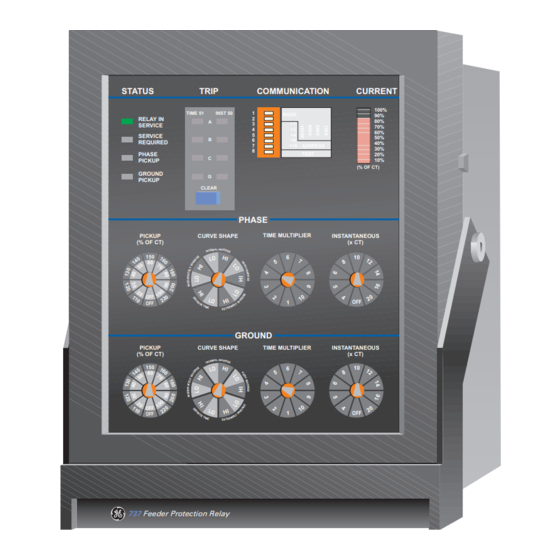
3.1 FRONT PANEL 3 SETUP AND OPERATION 3.1 FRONT PANEL 3.1.1 DESCRIPTION A front panel view of the 735/737 relay is shown below. An explanation of each of the numbered controls/indicators is con- tained in the following sections. 735 Feeder Protection Relay Figure 3–1: FRONT PANEL CONTROLS AND INDICATORS... -
Page 30: Controls
CURVE SHAPE: normal inverse PICKUP CURRENT: 480 A PHASE CT RATIO: 600:5 PHASE CURVE SHAPE: normal inverse LO PHASE PICKUP: 80/180 (480 A = 80% of 600 A) Figure 3–3: PHASE CURVE SHAPE SETTING 735/737 Feeder Protection Relay GE Power Management... -
Page 31: Phase Time Multiplier [3]
CT sensor. This setting is independent of the pickup dial setting. For example: CT RATING: 500:5 INSTANTANEOUS TRIP: 5000 A INSTANTANEOUS SETTING: 10 (i.e. 10 x 500 = 5000 A) Figure 3–5: PHASE INSTANTANEOUS TRIP SETTING GE Power Management 735/737 Feeder Protection Relay... -
Page 32: Ground Pickup [5]
For each curve, either the LO band or HI band of the ground pickup setting is selected. See Chapter 5 for actual curves and curve values in table form. Figure 3–7: GROUND CURVE SHAPE SETTING 735/737 Feeder Protection Relay GE Power Management... -
Page 33: Ground Time Multiplier [7]
CTs. This setting is independent of the GROUND PICKUP dial setting ranges from 0.1 to 16 times the ground CT rating. For example: PHASE CT RATING: 100:5 (residual ground sensing); GROUND FAULT TRIP: 400 A SETTINGS: Ground Fault Instantaneous = 4 (4 × 100 = 400 A) Figure 3–9: GROUND INSTANTANEOUS TRIP SETTING GE Power Management 735/737 Feeder Protection Relay... -
Page 34: Indicators
RELAY IN SERVICE Immediately after applying control power, the 735/737 relay performs a series of self checks. Assuming all checks are suc- cessful, the RELAY IN SERVICE indicator comes on and protection is operational. Continuous checks are also made by the relay of its internal circuitry. -
Page 35: Phase Current Indicator [12]
CT RATING: 200:5 PHASE PICKUP: 70% of CT (LO) PHASE CURVE: Normal inverse-LO ACTUAL CURRENT: 165 A DISPLAY: 165/200 = 83% 10% - 80% on 83% > 70% pickup so PHASE PICKUP indicator is flashing GE Power Management 735/737 Feeder Protection Relay... -
Page 36: Switches
Switches are used to set the communication parameters. Move the switch to the right for a 1 or ON. To use the communica- tions capability of the 735/737, a unique address must be chosen and the baud rate must match the system selected. Avail- able baud rates of 1200, 2400, 9600, and 19200 are selected using switches 1 and 2 as follows: (ON = switch to right). - Page 37 PICKUP OR CAUSE OF TRIP: Either pickup or latched cause of trip will energize the relays. This is the same as items 2 and 3 together. GE Power Management 735/737 Feeder Protection Relay...
- Page 38 CUSTOM SCHEME In addition to basic protection, the 735/737 can be field configured to perform more complex protection logic using an inter- nal non volatile setpoint memory. When "custom scheme" switch 8 on the side of the drawout relay is set to off, all custom scheme features are defeated so that the factory default shown for each option is active.
-
Page 39: Setup Program
The menus outlined below are used to establish communication with the relay, read/save setpoints to a computer file, con- figure computer settings and provide product information. Figure 3–10: SETUP SOFTWARE SYSTEM MENUS GE Power Management 735/737 Feeder Protection Relay 3-11... -
Page 40: Communicate
Setpoints > File > Save As to save to a file for later recall and downloading to the relay being tested. RETURN: When using a mouse, click on this menu to move cursor up to the next higher menu level. This selection is the same as pressing the ESCAPE key. 3-12 735/737 Feeder Protection Relay GE Power Management... -
Page 41: System Configuration
The computer screen is a mimic of the relay front panel indicators. It shows status, pickup, cause of trip indicators and the current bargraph. The computer screen information is constantly updated to agree with the relay front panel indications. GE Power Management 735/737 Feeder Protection Relay 3-13... -
Page 42: Actual Values
Select this item if the desired protection settings for the simulation are to be from the relay front panel dials. The relay front panel TEST switch 8 must be on for simulation mode to work. 3-14 735/737 Feeder Protection Relay GE Power Management... -
Page 43: File
Product features are displayed in this screen for reference. No operation is performed when this menu item is selected. 3.5.11 RETURN When using a mouse, click on this menu to move cursor up to the next higher menu level. This selection is the same as pressing the ESCAPE key. GE Power Management 735/737 Feeder Protection Relay 3-15... -
Page 44: Setup Example
TIME MULTIPLIER to 2. Set ground time o/c shift option switches 4=OFF, 3=OFF. Ground Instantaneous Trip: None Only the 200 ms delayed pickup of 240 A is required so set the GROUND INSTANTANEOUS dial to OFF. 3-16 735/737 Feeder Protection Relay GE Power Management... - Page 45 For a baud rate of 9600, 2=on, 1=off. Choose the combination of numbers that adds up to the required slave address: 10 = 2 (4=on) + 8 (6=on), (3=off, 5=off, 7=off). Disable communications test mode for normal operations (Test 8=off). The switch settings are: SWITCH POSITION SETTING 9600 baud Address 10 Test OFF GE Power Management 735/737 Feeder Protection Relay 3-17...
- Page 46 3.6 SETUP EXAMPLE 3 SETUP AND OPERATION 3-18 735/737 Feeder Protection Relay GE Power Management...
-
Page 47: Overview
4.1.3 DATA FRAME FORMAT AND RATE One data frame of an asynchronous transmission to or from a 735/737 consists of 1 start bit, 8 data bits, and 1 stop bit to produce a 10 bit data frame. This is important for transmission through modems at high bit rates (11 bit data frames are not supported by some modems at bit rates of greater than 300 bps). -
Page 48: Data Packet Format
FUNCTION CODE This is the second byte of every transmission. Modbus defines function codes of 1 to 127. The 735/737 implements some of these functions. See section 4.3 for details of the supported function codes. In a master request transmission the FUNC- TION CODE tells the slave what action to perform. -
Page 49: Error Checking
If a 735/737 Modbus slave device receives a transmission in which an error is indicated by the CRC-16 calculation, the slave device will not respond to the transmission. A CRC-16 error indicates than one or more bytes of the transmission were received incorrectly and thus the entire transmission should be ignored in order to avoid the slave device performing any incorrect operation. -
Page 50: Supported Modbus Functions
4.2 SUPPORTED MODBUS FUNCTIONS 4 MODBUS COMMUNICATIONS 4.2 SUPPORTED MODBUS FUNCTIONS 4.2.1 DESCRIPTION The following functions are supported by the 735/737: • 03: Read Setpoints • 04:Read Actual Values • 05: Execute Operation • 06: Store Single Setpoint (test/simulation) •... -
Page 51: Function Code 04: Read Actual Values
The maximum number of actual values that can be read in one transmission is 60 in the 735/737. The slave response to this function code is the slave address, function code, a count of the number of data bytes to follow, the data itself, and the CRC. -
Page 52: Function Code 05: Execute Operation
4.2.4 FUNCTION CODE 05: EXECUTE OPERATION Modbus Implementation: Force Single Coil 735/737 Implementation: Execute Operation This function code allows the master to request the 735/737 to perform specific operations. The operations that can be performed by the 735/737 are as follows: OPCODE... -
Page 53: Function Code 06: Store Single Setpoint
4.2.5 FUNCTION CODE 06: STORE SINGLE SETPOINT Modbus Implementation: Preset Single Register 735/737 Implementation: Store Single Setpoint This command allows the master to store a single setpoint into the memory of a slave device. The slave device response to this function code is to echo the entire master transmission. Note that broadcast mode is not allowed with this function code. -
Page 54: Function Code 16: Store Multiple Setpoints
This function code allows multiple setpoints to be stored into the 735/737 memory for test purposes only. Modbus "regis- ters" are 16 bit (two byte) values transmitted high order byte first. Thus all 735/737 setpoints are sent as two bytes. The slave device response to this function code is to echo the slave address, function code, starting address, the number of set- points loaded, and the CRC. -
Page 55: Error Responses
4.2.8 ERROR RESPONSES When a 735/737 detects an error other than a CRC error, a response will be sent to the master. The most significant bit of the FUNCTION CODE byte will be set to 1 (that is, the function code sent from the slave will be equal to the function code sent from the master plus 128). -
Page 56: Memory Map
4.3.1 MODBUS MEMORY MAP The data stored in the 735/737 is grouped as actual values and setpoints. Setpoints can be read and written by a master computer. Actual values can only be read. All setpoints and actual values are stored as two byte values. That is, each address listed in the memory map is the address of a two byte value. - Page 57 4 MODBUS COMMUNICATIONS 4.3 MEMORY MAP Table 4–1: 735/737 MODBUS MEMORY MAP (Sheet 2 of 2) GROUP ADDR DESCRIPTION RANGE STEP UNITS FOR- FACTORY DEFAULT SYSTEM 002A Phase Pickup dial setting 1 to 19 dial F108 CONFIG 002B Phase Curve Shape dial setting...
-
Page 58: Memory Map Data Formats
4.3 MEMORY MAP 4 MODBUS COMMUNICATIONS 4.3.2 MEMORY MAP DATA FORMATS Table 4–2: 735/737 MEMORY MAP DATA FORMATS (Sheet 1 of 5) FORMAT TYPE DESCRIPTION UNSIGNED INTEGER 0 to 65535 UNSIGNED INTEGER 0 to 6553.5 1 DECIMAL PLACE 2 UNSIGNED CHARACTERS... - Page 59 4 MODBUS COMMUNICATIONS 4.3 MEMORY MAP Table 4–2: 735/737 MEMORY MAP DATA FORMATS (Sheet 2 of 5) FORMAT TYPE DESCRIPTION F103 737 OUTPUT RELAYS XXXX XXX1 XXXX XXXX = Phase A time OC pickup/trip (51P-A) continued XXXX XX1X XXXX XXXX = Phase B time OC pickup/trip (51P-B)
- Page 60 4.3 MEMORY MAP 4 MODBUS COMMUNICATIONS Table 4–2: 735/737 MEMORY MAP DATA FORMATS (Sheet 3 of 5) FORMAT TYPE DESCRIPTION F107 CURVE SHAPE SWITCH Very Inverse (high) = 8 continued continued Extremely Inverse (low) = 9 Extremely Inverse (high) = 10...
- Page 61 4 MODBUS COMMUNICATIONS 4.3 MEMORY MAP Table 4–2: 735/737 MEMORY MAP DATA FORMATS (Sheet 4 of 5) FORMAT TYPE DESCRIPTION F110 60 = 11 continued 65 = 12 70 = 13 75 = 14 80 = 15 85 = 16...
- Page 62 4.3 MEMORY MAP 4 MODBUS COMMUNICATIONS Table 4–2: 735/737 MEMORY MAP DATA FORMATS (Sheet 5 of 5) FORMAT TYPE DESCRIPTION F114 CURVE SHIFT SETPOINT XXXX XXXX XXXX XXX1 = Switch 8 on = 1 XXXX XXXX XXXX XX1X = Switch 7 on = 1...
-
Page 63: Overcurrent Curves
For the graphs shown in this chapter, the per unit value (on the x-axis) is given as: Per Unit --- - --------------------------------------- - ⁄ × where: I = current input to relay = pickup current setpoint CT = CT secondary, that is1 or 5 A GE Power Management 735/737 Feeder Protection Relay... -
Page 64: Ansi Moderately Inverse Curves
A = 0.1735 (curve shape constant) S = curve shift multiplier B = 0.6791 (curve shape constant) M = 735/737 curve multiplier setpoint C = 0.8000 (curve shape constant) I = input current (in amps) D = –0.0800 (curve shape constant) Ipu = pickup current setpoint E = 0.1271 (curve shape constant) - Page 65 5 OVERCURRENT CURVES 5.2 ANSI CURVES 735/737 ANSI MODERATELY INVERSE CURVES GE POWER MANAGEMENT 1000 TIME MULTIPLIER 0.01 0.01 803658A4.CDR MULTIPLE OF PICKUP CURRENT (PER UNIT) Figure 5–1: ANSI MODERATELY INVERSE CURVES GE Power Management 735/737 Feeder Protection Relay...
-
Page 66: Ansi Normal Inverse Curves
A = 0.0274 (curve shape constant) S = curve shift multiplier B = 2.2614 (curve shape constant) M = 735/737 curve multiplier setpoint C = 0.3000 (curve shape constant) I = input current (in amps) D = –4.1899 (curve shape constant) Ipu = pickup current setpoint E = 9.1272 (curve shape constant) - Page 67 5 OVERCURRENT CURVES 5.2 ANSI CURVES 735/737 ANSI NORMAL INVERSE CURVE GE POWER MANAGEMENT 1000 TIME MULTIPLIER 0.01 0.01 803662A4.CDR MULTIPLE OF PICKUP CURRENT (PER UNIT) Figure 5–2: ANSI NORMAL INVERSE CURVES GE Power Management 735/737 Feeder Protection Relay...
-
Page 68: Ansi Very Inverse Curves
A = 0.0615 (curve shape constant) S = curve shift multiplier B = 0.7989 (curve shape constant) M = 735/737 curve multiplier setpoint C = 0.3400 (curve shape constant) I = input current (in amps) D = –0.2840 (curve shape constant) Ipu = pickup current setpoint E = 4.0505 (curve shape constant) - Page 69 5 OVERCURRENT CURVES 5.2 ANSI CURVES 735/737 ANSI VERY INVERSE CURVE GE POWER MANAGEMENT 1000 TIME MULTIPLIER 0.01 0.01 803660A4.CDR MULTIPLE OF PICKUP CURRENT (PER UNIT) Figure 5–3: ANSI VERY INVERSE CURVES GE Power Management 735/737 Feeder Protection Relay...
-
Page 70: Ansi Extremely Inverse Curves
A = 0.0399 (curve shape constant) S = curve shift multiplier B = 0.2294 (curve shape constant) M = 735/737 curve multiplier setpoint C = 0.5000 (curve shape constant) I = input current (in amps) D = 3.0094 (curve shape constant) Ipu = pickup current setpoint E = 0.7222 (curve shape constant) - Page 71 5 OVERCURRENT CURVES 5.2 ANSI CURVES 735/737 ANSI EXTREMELY INVERSE CURVE GE POWER MANAGEMENT 1000 TIME MULTIPLIER 0.01 0.01 MULTIPLE OF PICKUP CURRENT (PER UNIT) 803661A4.CDR Figure 5–4: ANSI EXTREMELY INVERSE CURVES GE Power Management 735/737 Feeder Protection Relay...
- Page 72 S M 0.1 The trip time is given by: where: T = trip time (in seconds) S = curve shift multiplier M = 735/737 curve multiplier setpoint I = input current (in amps) Ipu = pickup current setpoint SHIFT CURVE CURRENT (per unit I /I 1.05...
-
Page 73: Definite Time Curves
5 OVERCURRENT CURVES 5.3 DEFINITE TIME CURVES 735/737 DEFINITE TIME CURVES GE POWER MANAGEMENT 1000 TIME MULTIPLIER 0.01 0.01 803650A4.CDR MULTIPLE OF PICKUP CURRENT (PER UNIT) Figure 5–5: DEFINITE TIME CURVES GE Power Management 735/737 Feeder Protection Relay 5-11... -
Page 74: Iac Curves
A = 0.043 (curve shape constant) S = curve shift multiplier B = 0.061 (curve shape constant) M = 735/737 curve multiplier setpoint C = 0.620 (curve shape constant) I = input current (in amps) D = –0.001 (curve shape constant) Ipu = pickup current setpoint E = 0.022 (curve shape constant) - Page 75 5 OVERCURRENT CURVES 5.4 IAC CURVES 735/737 IAC SHORT INVERSE CURVE GE POWER MANAGEMENT CURVE MULTIPLIER 0.01 803655A4.CDR MULTIPLE OF PICKUP CURRENT (PER UNIT) Figure 5–6: IAC SHORT INVERSE CURVES GE Power Management 735/737 Feeder Protection Relay 5-13...
-
Page 76: Iac Inverse Curves
A = 0.2078 (curve shape constant) S = curve shift multiplier B = 0.8630 (curve shape constant) M = 735/737 curve multiplier setpoint C = 0.8000 (curve shape constant) I = input current (in amps) D = –0.4180 (curve shape constant) Ipu = pickup current setpoint E = 0.1947 (curve shape constant) - Page 77 5 OVERCURRENT CURVES 5.4 IAC CURVES 735/737 IAC GE POWER MANAGEMENT INVERSE CURVE 1000 CURVE MULTIPLIER CURVE MULTIPLIER 803659A4.CDR MULTIPLE OF PICKUP CURRENT (PER UNIT) Figure 5–7: IAC INVERSE CURVES GE Power Management 735/737 Feeder Protection Relay 5-15...
-
Page 78: Iac Very Inverse Curves
A = 0.090 (curve shape constant) S = curve shift multiplier B = 0.796 (curve shape constant) M = 735/737 curve multiplier setpoint C = 0.100 (curve shape constant) I = input current (in amps) D = –1.289 (curve shape constant) Ipu = pickup current setpoint E = 7.959 (curve shape constant) - Page 79 5 OVERCURRENT CURVES 5.4 IAC CURVES 735/737 IAC VERY INVERSE CURVE GE POWER MANAGEMENT 1000 CURVE MULTIPLIER 803657A4.CDR MULTIPLE OF PICKUP CURRENT (PER UNIT) Figure 5–8: IAC VERY INVERSE CURVES GE Power Management 735/737 Feeder Protection Relay 5-17...
-
Page 80: Iac Extremely Inverse Curves
A = 0.004 (curve shape constant) S = curve shift multiplier B = 0.638 (curve shape constant) M = 735/737 curve multiplier setpoint C = 0.620 (curve shape constant) I = input current (in amps) D = 1.787 (curve shape constant) Ipu = pickup current setpoint E = 0.246 (curve shape constant) - Page 81 5 OVERCURRENT CURVES 5.4 IAC CURVES 735/737 IAC EXTREMELY INVERSE CURVE GE POWER MANAGEMENT 1000 CURVE MULTIPLIER 0.01 803656A4.CDR MULTIPLE OF PICKUP CURRENT (PER UNIT) Figure 5–9: IAC EXTREMELY INVERSE CURVES GE Power Management 735/737 Feeder Protection Relay 5-19...
-
Page 82: Iec Curves
T = trip time (in seconds) K = 0.050 (curve shape constant) S = curve shift multiplier E = 0.040 (curve shape constant) M = 735/737 curve multiplier setpoint I = input current (in amps) Ipu = pickup current setpoint MULT CURRENT (per unit I /I ) –... - Page 83 5 OVERCURRENT CURVES 5.5 IEC CURVES 735/737 IEC SHORT TIME CURVE GE POWER MANAGEMENT 1000 CURVE MULTIPLIER FACEPLATE EQUIVALENT 803654A4.CDR MULTIPLE OF PICKUP CURRENT (PER UNIT) Figure 5–10: IEC SHORT TIME CURVES GE Power Management 735/737 Feeder Protection Relay 5-21...
-
Page 84: Iec A Curves
T = trip time (in seconds) K = 0.140 (curve shape constant) S = curve shift multiplier E = 0.020 (curve shape constant) M = 735/737 curve multiplier setpoint I = input current (in amps) Ipu = pickup current setpoint MULT CURRENT (per unit I /I )–... - Page 85 5 OVERCURRENT CURVES 5.5 IEC CURVES 735/737 IEC-A CURVE (NORMAL INVERSE) GE POWER MANAGEMENT 1000 CURVE MULTIPLIER FACEPLATE EQUIVALENT 803653A4.CDR MULTIPLE OF PICKUP CURRENT (PER UNIT) Figure 5–11: IEC A CURVES GE Power Management 735/737 Feeder Protection Relay 5-23...
-
Page 86: Iec B Curves
T = trip time (in seconds) K = 13.500 (curve shape constant) S = curve shift multiplier E = 1.000 (curve shape constant) M = 735/737 curve multiplier setpoint I = input current (in amps) Ipu = pickup current setpoint MULT CURRENT (per unit I /I )–... - Page 87 5 OVERCURRENT CURVES 5.5 IEC CURVES 735/737 IEC-B CURVE (VERY INVERSE) GE POWER MANAGEMENT 1000 CURVE MULTIPLIER FACEPLATE EQUIVALENT 0.01 803652A4.CDR MULTIPLE OF PICKUP CURRENT (PER UNIT) Figure 5–12: IEC B CURVES GE Power Management 735/737 Feeder Protection Relay 5-25...
-
Page 88: Iec C Curves
T = trip time (in seconds) K = 80.000 (curve shape constant) S = curve shift multiplier E = 2.000 (curve shape constant) M = 735/737 curve multiplier setpoint I = input current (in amps) Ipu = pickup current setpoint MULT CURRENT (per unit I /I )–... - Page 89 5 OVERCURRENT CURVES 5.5 IEC CURVES 735/737 IEC-C CURVE (EXTREMELY INVERSE) GE POWER MANAGEMENT 1000 CURVE MULTIPLIER FACEPLATE EQUIVALENT 0.01 803651A4.CDR MULTIPLE OF PICKUP CURRENT (PER UNIT) Figure 5–13: IEC C CURVES GE Power Management 735/737 Feeder Protection Relay 5-27...
- Page 90 5.5 IEC CURVES 5 OVERCURRENT CURVES 5-28 735/737 Feeder Protection Relay GE Power Management...
-
Page 91: Testing
6.1.4 PHASE CURRENT READING ACCURACY TEST The 735/737 relay must read the phase current signals input from the CTs correctly to provide the instantaneous and timed overcurrent protection. To determine if the relay is reading correctly set the phase pickup dial to 100% of the CT primary. - Page 92 6.1 PROCEDURES 6 TESTING Figure 6–1: TEST SETUP 735/737 Feeder Protection Relay GE Power Management...
-
Page 93: Instantaneous Phase Overcurrent Timing Test
(G12) should be connected together and the test performed with respect to safety ground. Make sure to disconnect the filter ground (G11) before performing this test. Refer to Section 2.2.7 HI-POT TESTING on page 2–12 for more information. GE Power Management 735/737 Feeder Protection Relay... -
Page 94: Test Records
6.2 TEST RECORDS 6 TESTING 6.2 TEST RECORDS 6.2.1 735/737 TEST RECORD MODEL NUMBER: DATE FIRMWARE NUMBER: TESTED BY SERIAL NUMBER: STATION: CIRCUIT 6.2.2 COMMUNICATIONS TEST TYPE OF COMMUNICATIONS ESTABLISHED STATUS 6.2.3 PHASE CURRENT READING ACCURACY TEST PHASE AND LEVEL... -
Page 95: Instantaneous Phase Overcurrent Pickup Test
6.2.8 INSTANTANEOUS GROUND FAULT OVERCURRENT TIMING TEST GROUND LEVEL DIAL SETTING INPUT EXPECTED MEASURED STATUS (xCT) CURRENT ( TIME (ms) TIME (ms) ≤ 35 GROUND / LOW END ≤ 35 GROUND / HIGH END GE Power Management 735/737 Feeder Protection Relay... -
Page 96: Phase Overcurrent Curve Verification
6.2 TEST RECORDS 6 TESTING 6.2.9 PHASE OVERCURRENT CURVE VERIFICATION PICKUP CURVE SHAPE TIME TIME INPUT EXPECTED MEASURED STATUS LEVEL MULT SHIFT CURRENT ( ) TIME TIME 735/737 Feeder Protection Relay GE Power Management... -
Page 97: Ground Fault Overcurrent Curve Verification
6.2.12 HI POTENTIAL TEST Note the Filter Ground (terminal G11) must be left floating for this test. See Section 2.2.7 HI-POT TESTING on page 2–12 for details. HIPOT LEVEL (kV) DURATION ( STATUS GE Power Management 735/737 Feeder Protection Relay... - Page 98 6.2 TEST RECORDS 6 TESTING 735/737 Feeder Protection Relay GE Power Management...
-
Page 99: Commissioning
Custom Scheme > Time Overcurrent Curve Shape (ANSI, IAC, BS142) Custom Scheme > Block Instantaneous on Autoreclose (Disabled, Enabled) Custom Scheme > Aux Trip Relay (Main Trip, 86 Lockout, Ground Trip) COMMUNICATIONS SETTINGS Baud Rate Communications Address GE Power Management 735/737 Feeder Protection Relay... - Page 100 7.1 SETTINGS TABLE 7 COMMISSIONING 735/737 Feeder Protection Relay GE Power Management...
-
Page 101: Overcurrent Protection Sample Calculations
Level for ground instantaneous element = 2400 A primary Secondary ground instantaneous level = 2400 A × (5 / 600) = 20 A • • Ground Instantaneous dial setting = 20 A / 5 A = 4 GE Power Management 735/737 Feeder Protection Relay... -
Page 102: Feeder Dedicated To A Transformer
This current is less than the maximum possible transformer inrush current of 1255 A. Thus this value cannot be used. Instead set instantaneous pickup at 120% of inrush level. Instantaneous pickup current level = 1.2 × 1255 = 1506 A Phase Instantaneous dial setting = 1506 A / 150 A ≈ 10 735/737 Feeder Protection Relay GE Power Management... -
Page 103: Dos And Don'ts
735/737 relays have only 31 unique addresses. As each device on the communication link must have a unique address only 31 735/737 relays can be used on a single link. Other devices could however be used as well on the link though. -
Page 104: Warranty Information
Warranty shall not apply to any relay which has been subject to mis- use, negligence, accident, incorrect installation or use not in accor- dance with instructions nor any unit that has been altered outside a GE Power Management authorized factory outlet. - Page 105 ............. 3-9 ALGORITHM ............4-2, 4-3 multiplier shift ..............3-4, 3-6 ..............1-6 pickup CT BURDEN shape ................ 3-4 ............. 1-6 ............... 3-16 specifications 600/5 ..............2-8 trip ..............3-6, 3-7 description specifications ............. 1-6 GE Power Management 735/737 Feeder Protection Relay...
- Page 106 ..............3-14 .............3-10 SETPOINTS aux trip relay ............3-9 reading with Modbus ............4-4 cause of trip relay ..........4-7, 4-8 description ..............2-8 storing with Modbus ............ 3-12 ............3-14 SETPOINTS EDITOR disable trip relays 735/737 Feeder Protection Relay GE Power Management...
- Page 107 ............1-6 .......... 2-6 SPECIFICATIONS TYPICAL WIRING DIAGRAM STATUS INDICATORS ........... 3-6 ..........2-12 SYSTEM GROUNDING ..............A-4 WARRANTY WIRING DIAGRAM ............2-6 ............1-8 .............. 2-3 TEMPERATURE WITHDRAWAL ............6-4 TEST RECORDS GE Power Management 735/737 Feeder Protection Relay...
- Page 108 INDEX 735/737 Feeder Protection Relay GE Power Management...
- Page 109 NOTES GE Power Management 735/737 Feeder Protection Relay...
- Page 110 GE POWER MANAGEMENT WEBSITE The latest product information for the 735/737 Feeder Protection Relay is available on the Internet via the GE Power Man- agement home page: http://www.GEindustrial.com/pm This site provides access to the following customer services: • Digital Products Directory •...