
Subscribe to Our Youtube Channel
Related Manuals for Primes LQM+ 20


Summary of Contents for Primes LQM+ 20
-
Page 1: Operating Manual
Operating Manual Translation of the original instructions LaserQualityMonitor LQM+ LQM+ 20, LQM+ 200/500, LQM+ HP (10/20 kW) LaserDiagnosticsSoftware LDS Revision 02/2019 EN... - Page 3 LaserQualityMonitor LQM+ IMPORTANT! READ CAREFULLY BEFORE USE. KEEP FOR FUTURE USE. Revision 02/2019 EN...
-
Page 4: Table Of Contents
Preparation and installation position ..................14 Manually aligning the LaserQualityMonitor LQM+ ..............15 7.2.1 Alignment tool ......................15 7.2.2 Manual alignment of the LQM+ 20 basic device and the LQM+ 200/500 with attenuator ......................15 7.2.3 Fine adjustment at the 1 attenuator .................16 Install the LaserQualityMonitor LQM+ ..................17 7.3.1... - Page 5 18.2 LQM+ 200/500 (without bottom plate) ..................51 18.3 LQM+ HP ..........................52 Appendix 19.1 Changing the factory setting on the LQM+ 20/200UV .............53 19.2 HighYAG collimation module up to 6 kW .................55 19.2.1 Key data for the cooling system for the HighYAG collimation module ......56 19.2.2...
- Page 6 • Beam quality factor M² PRIMES is responsible for both the development, production, and calibration of the measuring devices. This guarantees optimum quality, excellent service, and a short reaction time, providing the basis for us to meet all of our customers’ requirements quickly and reliably.
-
Page 7: Basic Safety Instructions
LaserQualityMonitor LQM+ Basic safety instructions Intended use The LaserQualityMonitor LQM+ is exclusively intended for measurements which are carried out in or nearby the optical path of high power lasers. Please mind and adhere to the specifications and limit values given in chapter 17 „Technical data“... - Page 8 LaserQualityMonitor LQM+ • Ensure that the device is mounted securely to prevent any movement of the device relative to the beam axis and thus reduce the risk of scattered radiation. This in the only way to ensure optimum performance during the measurement. Employing qualified personnel The device may only be operated by qualified personnel.
-
Page 9: Symbol Explanations
LaserQualityMonitor LQM+ Symbol explanations The following symbols and signal words indicate possible residual risks: DANGER Means that death or serious physical injuries will occur if necessary safety precautions are not taken. WARNING Means that death or serious physical injuries may occur if necessary safety precautions are not taken. -
Page 10: About This Operating Manual
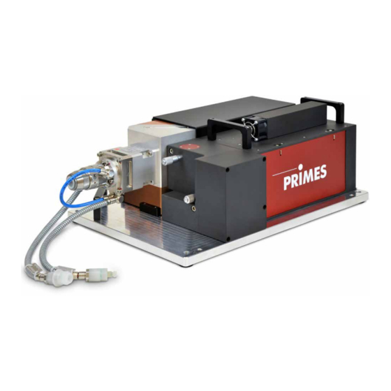
Cw lasers can be measured and pulsed lasers can also be measured using an internal trigger. The electronics and all optical components shown are installed in the LQM+ 20 basic device. The LQM+ 20 basic device can be supplemented by a front-end module with a beam splitter, an absorber and an align- ment unit, which enables the use of the device even in the multikilowatt range. - Page 11 LaserQualityMonitor LQM+ Fig. 5.1: Components of the LQM+ 20 basic device Attenuator Alignment unit Power meter (LQM+ 500 only) Fig. 5.2: Components of the LQM+ 200/500 Attenuator Alignment unit Absorber with power meter Attenuator with beam splitter Fig. 5.3: Components of the LQM+ HP (10/20 kW)
-
Page 12: Measuring Principle
Measuring objective 1:1 OD filter CCD sensor Position 2 Position 1 (illustrated inserted) (illustrated not inserted) Fig. 5.4: Optical assembly of the LQM+ 20 basic device Raw beam Scaning range CCD sensor Focusing optic Measuring objective Fig. 5.5: Measuring Principle... -
Page 13: Short Overview Installation
LaserQualityMonitor LQM+ Short overview installation Installing the LaserDiagnosticsSoftware LDS on the computer See separate Operating Manual of the LaserDiagnos- • Software is part of the scope of delivery ticsSoftware LDS Taking safety precautions Chapter 1 on page 7 Prepare Installation (only during open beam measurement) Chapter 7 on page 14 •... -
Page 14: Transport
X Handle the device carefully when transporting or installing it. X To avoid contamination, cover the apertures with the provided lid or optical tape. X Only transport the device in the original PRIMES transport box. NOTICE Damage/destruction of the device caused by leaking or freezing cooling water Leaking cooling water can damage the device. -
Page 15: Manually Aligning The Laserqualitymonitor Lqm
Manual alignment of the LQM+ 20 basic device and the LQM+ 200/500 with 1 attenuator LQM+ 20 basic device LQM+ 200/500 with 1 attenuator Fig. 7.2: Alignment tool mounted on the LQM+ 20 basic device and the LQM+ 200/500 with 1 attenuator Revision 02/2019 EN... -
Page 16: Fine Adjustment At The 1
LaserQualityMonitor LQM+ 7.2.3 Fine adjustment at the 1 attenuator With the attenuator, the angle of incidence of the laser beam can be finely adjusted to the appropriate angle with two integrated micrometer screws (see Fig. 7.3 on page 16). The laser beam can thus be aligned within the boundaries for the LaserQualityMonitor LQM+. The feedback to change the beam position through fine adjustments is issued via the LaserDiagnosticsSoftware LDS (see chapter 11.4 on page 35). -
Page 17: Install The Laserqualitymonitor Lqm
44.3 Fig. 7.4: Fastening threaded holes LQM+ 20/200/500 without bottom plate There are four M6 mounting threads on the underside of the device for fastening it onto a holder provided by the customer. We recommend screws of the strength class 8.8. -
Page 18: Install The Lqm+ 200/500 With Bottom Plate
LaserQualityMonitor LQM+ 7.3.2 Install the LQM+ 200/500 with bottom plate Fig. 7.5: Fastening threaded holes LQM+ 200/500 with bottom plate For the connection of a customer specific part, there are four threads M6 in the bottom plate. We recom- mend screws of the strength class 8.8. 4 threaded holes M6 Revision 02/2019 EN... -
Page 19: Install The Lqm+ Hp With Bottom Plate
LaserQualityMonitor LQM+ 7.3.3 Install the LQM+ HP with bottom plate Fig. 7.6: Fastening bores and alignment threads LQM+ HP with bottom plate 4 mounting holes Ø 7.8 mm 4 threaded holes M8 for the alignment Revision 02/2019 EN... -
Page 20: Connect Cooling Circuit (Lqm+ Hp And Lqm+ 500 Only)
LaserQualityMonitor LQM+ Connect cooling circuit (LQM+ HP and LQM+ 500 only) DANGER Fire hazard; Damage/Destruction of the device due to overheating If there is no water cooling or a water flow rate which is insufficient, there is a danger of overheating, which can damage the device or set it on fire. X Operate the device with a connected water cooling and a sufficient water flow rate only. -
Page 21: Humidity
LaserQualityMonitor LQM+ Humidity • The device must not be operated in a condensing atmosphere. The humidity has to be considered in order to prevent condensates within and outside the device. • The temperature of the cooling water must not be lower than the dew point (see Tab. 8.1 on page 21). NOTICE Damage/Destruction of the device due to condensing water Condensation water inside of the objective will lead to damage. -
Page 22: Water Connections And Water Flow Rate
LaserQualityMonitor LQM+ Water connections and water flow rate 8.4.1 LQM+ HP (10 kW and 20 kW) LQM+ HP (10 kW) Connection diameter Recommended flow rate Minimum flow rate PE hoses 16 mm 7 l/min – 8 l/min (1 l/(min · kW) Not lower than 4.5 l/min LQM+ HP (20 kW) Connection diameter Recommended flow rate... -
Page 23: Remove The Sealing Plugs Of The Water Connections
LaserQualityMonitor LQM+ 8.4.3 Remove the sealing plugs of the water connections 1. Please push down the release ring of the connection Release ring and pull out the plug with your free hand. 2. Remove the sealing plugs of the water connections and keep it in a save place. -
Page 24: Electrical Connection
The LaserQualityMonitor LQM+ requires a supply voltage of 24 V ±5 % (DC) for the operation. A suitable power supply is included in the scope of delivery. Please use only the provided PRIMES power supply and connection lines. Please ensure that all electrical connections have been established and switch the device on before starting the LaserDiagnosticsSoftware LDS. -
Page 25: Pin Assignment
Harting M12-P-PCB-THR-2PC-5P-LCOD-M-STR (view: connector side) Function +24 V Not assigned Not assigned FE (functional earth) Tab. 9.1: Connection socket for the PRIMES power supply in the connection panel 9.2.2 Inlet external trigger BNC connector (view: connector side) Function +5 V (Trigger signal) Fig. 9.2: Connection socket Inlet for an external trigger in the connection panel 9.2.3... -
Page 26: Safety Facilities
LaserQualityMonitor LQM+ Safety facilities 9.3.1 Monitoring side access to the measuring objective and neutral-density filters A safety switch monitors the side frame plates. When the frame plate is removed, the laser will switch off if the safety interlock is connected. DANGER Serious eye or skin injury due to laser radiation When the safety interlock is not connected, radiation (Laser class 4) reflected during mea-... -
Page 27: Safety Interlock
The port for a safety interlock, which monitors the 1 and 2 attenuator for excess temperature and whether or not the side frame plates are opened, is integrated into the LaserQualityMonitor LQM+ 20 basic device. DANGER Serious eye or skin injury due to laser radiation; Damage/Destruction of the device If the safety interlock is not connected, the safety equipment of the device will not be moni- tored. -
Page 28: Connection To The Pc And Connect Power Supply
X Please turn off the PRIMES power supply before disconnecting the cables. 1. Connect the device with the PC via a crossover cable or with the network via a patch cable. -
Page 29: Status Display
LaserQualityMonitor LQM+ Status display The status display consists of an indicator field that indicates the various states of the LaserQualityMonitor LQM+ with various colors. Color Meaning White The device is switched on and operational Yellow Measuring Lights up briefly while the measuring plane is being recorded. Staying lit signals a device error. -
Page 30: Measurement
LaserQualityMonitor LQM+ Measurement 11.1 Safety instructions DANGER Serious eye or skin injury due to laser radiation During the measurement the laser beam is guided on the device, which causes scattered or directed reflection of the laser beam (laser class 4). The LaserQualityMonitor LQM+ must not be operated in any of the available configurations without taking the following precautions. -
Page 31: Selection And Change Of The Measuring Objective And The Neutral Density Filter
LaserQualityMonitor LQM+ 11.2 Selection and change of the measuring objective and the neutral density filter 11.2.1 Selection of the measuring objective The selection of the correct measuring objective is of vital importance for the measurement quality. The limi- tation of use for the 1:1 or 5:1 measuring objectives is shown in the diagram Tab. 11.1 on page 31. M²... -
Page 32: Exchanging The Measuring Objective Or The Neutral Density Filter
LaserQualityMonitor LQM+ 11.2.2 Exchanging the measuring objective or the neutral density filter For changing a measuring objective or the neutral-density filter, the plate on the side of the LaserQualityMoni- tor LQM+ has to be opened: 1. Turn off the laser. 2. -
Page 33: Neutral Density Filter
LaserQualityMonitor LQM+ NOTICE Damage of the device Contamination in the device can damage the optical components. X Seal unused slots with the provided dummy inserts. Fig. 11.2: Dummy insert DANGER Serious eye or skin injury due to laser radiation When the safety interlock is not connected and the the side frame plate is opened, radiation (Laser class 4) reflected during measuring operation may escape from the device. -
Page 34: Connect The Laserqualitymonitor Lqm+ With The Laserdiagnosticssoftware Lds
LaserQualityMonitor LQM+ 11.3 Connect the LaserQualityMonitor LQM+ with the LaserDiagnosticsSoftware LDS 11.3.1 Connect device Turn on the LaserQualityMonitor LQM+. The operating mode is shown in the status display (see chapter 10 on page 29). Start the LaserDiagnosticsSoftware LDS. Click on the Devices tab. Click on the + Connect to device button under the tab. -
Page 35: Set Up The Laserqualitymonitor Lqm+ With The Laserdiagnosticssoftware Lds
LaserQualityMonitor LQM+ 11.4 Set up the LaserQualityMonitor LQM+ with the LaserDiagnosticsSoftware LDS After performing manual alignment with the alignment tool as described in chapter 7.2 on page 15 (only for an open beam measurement) or after inserting the fiber, you can check the alignment using a function of the LaserDiagnosticsSoftware LDS. -
Page 36: Start Beam Search
LaserQualityMonitor LQM+ 11.4.2 Start beam search Follow the safety instructions in chap- ter 11.1 on page 30. Turn on the laser. Click on the Start button. The progress of beam pointing determination is indicated when Pre- caustic, Measuring beam pointing and then Adjustment successful are displayed in the notifications: Pre-caustic During the pre-caustic, the optimal z1 and... - Page 37 LaserQualityMonitor LQM+ The display of the beam position in the Position and Angle windows can be switched to a display of Beam pointing stability by clicking on the gear icon You can reset the values for beam position stability in the Position and Angle windows by pressing the Reset button. You can log the Beam pointing stability as described in chapter 11.4.3 on page 38.
-
Page 38: Log Beam Pointing Stability
LaserQualityMonitor LQM+ 11.4.3 Log beam pointing stability You can log the beam pointing stability under Device control > Settings: Enter the value of 0 in the Plane quantity field. Click on the Projects tab. Click on the Start button. • Continuous measurement data for beam position stability is generated in the project tree. -
Page 39: If The Laser Beam Is Not Found
LaserQualityMonitor LQM+ 11.4.4 If the laser beam is not found If the laser beam isn’t found during the automatic beam search or if the laser beam is too large for the mea- suring area (the laser beam exceeds the size of the CCD sensor), you can manually enter the position of the measurements z1 and z2 into the LaserDiagnosticsSoftware LDS for the beam search. -
Page 40: Perform An Automatic Caustic Measurement
LaserQualityMonitor LQM+ 11.5 Perform an automatic caustic measurement For the purpose of getting to know the LaserQualityMonitor LQM+, this chapter describes an automatic caustic measurement with the LaserDiagnosticsSoftware LDS as an example. For a detailed description of the software installation, file management and evaluation of the measured data, please refer to the separate operating manual LaserDiagnosticsSoftware LDS. -
Page 41: Configure Settings (Device Control > Settings)
LaserQualityMonitor LQM+ 11.5.2 Configure settings (Device control > Settings) Click on the Settings tab. Select the calibrated wavelength of your LQM+ in nm. Enter the laser wavelength used in Enter the laser output in W. Only when measuring a time series Enter the number of automatic caus- tic measurements. -
Page 42: Starting An Automatic Caustic Measurement
LaserQualityMonitor LQM+ 11.5.4 Starting an automatic caustic measurement Follow the safety instructions in chap- ter 11.1 on page 30. Turn on the laser. Click on the Start button. The progress of the measurement is shown in the Pre-caustic, Measure- ment caustic displays and then in Measurement ended: Pre-caustic As the indication is being displayed, the... -
Page 43: Perform Power Measurement
LaserQualityMonitor LQM+ 11.6 Perform power measurement With LaserQualityMonitor LQM+ devices, the power measurement can be performed at 500 W with a 1 tenuator. When there is an additional 2 attenuator, the power can be measured separately at the 2 attenu- ator. The measurements at the 1 and 2 attenuators are performed in the same way. -
Page 44: Configure Settings (Device Control)
LaserQualityMonitor LQM+ 11.6.2 Configure settings (Device control) Start and end a measurement as described in chapter 11.6.3 on pa- ge 44. Before the device offset can be deter- mined, the device must go through a thermalization period. After a measurement has ended and without the laser turned on, press the Start button. -
Page 45: Measurement Results Display
LaserQualityMonitor LQM+ 11.6.4 Measurement results display The measurement results are shown in the opened tool Power Measurement after the measurement is com- pleted (see below). A detailed description of the tools and the assessment of the measuring results can be found in the separate operating manual for the LaserDiagnosticsSoftware LDS. -
Page 46: Troubleshooting
A measuring objectiv from Check the inserted measuring objective. brated for this device, the accuracy can a different device may have PRIMES should calibrate the measuring be increased considerably. been inserted. objectiv for higher accuracy. Measurement can’t be taken, the con- The device wasn’t able to... -
Page 47: Maintenance And Service
“EAR“) with the number WEEE-reg.-no. DE65549202. Provided that you are located in the EU, you are welcome to send your PRIMES devices to the following ad- dress, where they will be disposed free of charge (this service does not include shipping costs): PRIMES GmbH Max-Planck-Str. -
Page 48: Declaration Of Conformity
LaserQualityMonitor LQM+ Declaration of conformity Revision 02/2019 EN... -
Page 49: Technical Data
18 l/min Cooling water temperature T –- Dew point temperatur < T < 30 °C Please consult with PRIMES before doing anything that does not comply with this specification. Communication Interface Ethernet Dimensions and Weight Dimensions (L x W x H) -
Page 50: Dimensions
LaserQualityMonitor LQM+ Dimensions 18.1 LQM+ 20 View A Ansicht A All dimensions in mm (general tolerance ISO 2768-v) Revision 02/2019 EN... -
Page 51: Lqm+ 20
LaserQualityMonitor LQM+ 18.2 LQM+ 200/500 (without bottom plate) 299.3 413.7 View A Ansicht A All dimensions in mm (general tolerance ISO 2768-v) Revision 02/2019 EN... -
Page 52: Lqm+ Hp
LaserQualityMonitor LQM+ 18.3 LQM+ HP 101.5 All dimensions in mm (general tolerance ISO 2768-v) Revision 02/2019 EN... -
Page 53: Appendix
To prevent the device from getting damaged and to avoid a positioning of a prism close to the internal focus, a shortened positioning range can be chosen. The LaserQualityMonitor LQM+ 20/200UV is typically delivered with the shortened positioning range as a factory setting. Factory settings for standard and shortened positioning range are preset by a jumper, see picture below. - Page 54 LaserQualityMonitor LQM+ NOTICE Component susceptible to electrostatic discharge The circuit board could be destroyed by electrostatic discharge. X Before reconnecting the jumper, put on an ESD armband. Before switching the jumpers, put on an ESD armband. On the board you can find a jumper which has to be brought Position Shortened positioning range into the desired position.
-
Page 55: Highyag Collimation Module Up To 6 Kw
X Protect yourself from laser radiation by separating protective devices (e.g. by using appro- priate shielding). As an option PRIMES offers a 67 mm HighYAG collimation module which can be mounted directly to the 2 attenuator of the LQM+ HP. Specifications Max. -
Page 56: Key Data For The Cooling System For The Highyag Collimation Module
LaserQualityMonitor LQM+ 19.2.1 Key data for the cooling system for the HighYAG collimation module Specifications Max. cooling water pressure 6 bar Min. cooling water flow rate 2 l/min Cooling water quality Deionized water with corrosion inhibitor Filter mesh < 100 µm Tab. 19.2: Specifications of the cooling system Cooling circuit LQM+ HP (return flow) Cooling circuit... -
Page 57: Remove/Install The Highyag Collimation Module
LaserQualityMonitor LQM+ 19.2.3 Remove/Install the HighYAG collimation module Necessary tools: • Allen key, a. f. 2.5 mm • Allen key, a. f. 3 mm NOTICE Damage/Destruction of optical components A contaminated measuring objectiv can heat up, change optical properties and potentially be damaged. X To avoid contamination, only perform work in a clean environment. -
Page 58: Choosing The Measuring Objective With A Highyag Collimation Module Installed
LaserQualityMonitor LQM+ 19.2.4 Choosing the measuring objective with a HighYAG collimation module installed Example 1: λ = 1 030 nm M² = 12 = 100 µm fibercore = focal length ⋅ fibercore fibercore = 299 µm To enable a measurement within ±3 z the estimated number of illuminated pixels at the focus should be less than 350. - Page 59 LaserQualityMonitor LQM+ M² Fig. 19.4: Range of application of the LQM+ measuring objectives Measuring objective (MOB) 1:1 --> Measuring objective (MOB) 5:1 --> The two examples demonstrates the calculation of beam parameters based on a given collimator focal length.
-
Page 60: Ipg Collimation Module Up To 20 Kw
(20 kW) with any collimator that is suitable for the required power range and produces a minimum of artifacts. At the date of issue (August 2018), we are only aware of one supplier (IPG Photonics) delivering collimator units with a specification of 20 kW. As an option, PRIMES can combine the LQM+ HP with a collimator from that supplier. -
Page 61: Possible Combinations Of The Laserqualitymonitor Lqm+ Hp (20 Kw) With Ipg Collimators
LaserQualityMonitor LQM+ 19.3.1 Possible combinations of the LaserQualityMonitor LQM+ HP (20 kW) with IPG collimators Possible combinations of the LQM+ HP (20 kW) with IPG collimators and resulting nummerical aperture (NA) for a measurement. Color code is corresponding to the resulting diameter of the collimated light. Light green: diameter suitable for single mode measurement (< 2 mm ∙... -
Page 62: The Use Of The Measuring Objectives 1:1 And 5:1
0,07 0,1401 14,03 16,84 22,45 25,25 28,06 0,075 0,1501 15,04 18,05 24,06 27,07 30,08 0,08 0,1601 16,05 19,26 25,67 28,88 32,09 0,085 0,1702 17,06 20,47 27,29 30,70 34,11 LaserQualityMonitor LQM+ 0,09 0,1802 18,07 21,68 28,91 32,52 36,14 0,095 0,1902 19,08 22,90 30,53 34,35... -
Page 63: Optical Path In Lqm+ Hp (With Ipg Collimator)
19.4 Optical path in LQM+ HP (with Collimator) f = 67 Attenuator Beamsplitter Fiber Collimator Beam entrance LQM+ LQM+ 20 basic device 0 to 140 z = 280 z = 0 Adjustable prism 5:1 optics Attenuator 1:1 optics Fig. 19.5:... -
Page 64: Formula And Algorithms For Raw Beam Back Calulation
LaserQualityMonitor LQM+ Formula and algorithms for raw beam back calulation To calculate the raw parameters from the measured beam parameters of the focus, the formula given in ISO11146 is used. Index F describes the beam parameters of the focus. Fig. 20.1: Raw beam back calculation Beam waist radius within the raw beam Far field divergence...
Need help?
Do you have a question about the LQM+ 20 and is the answer not in the manual?
Questions and answers