Advertisement
Advertisement
Table of Contents

Related Manuals for Scotsman Brilliance SCCP50MA-1SU


Summary of Contents for Scotsman Brilliance SCCP50MA-1SU
- Page 1 Scotsman Technical Training‐Cubers...
- Page 2 Major Topics • Overview • Installation • Start Up • Sequence of Operation • Maintenance • Diagnostics • Service Procedures...
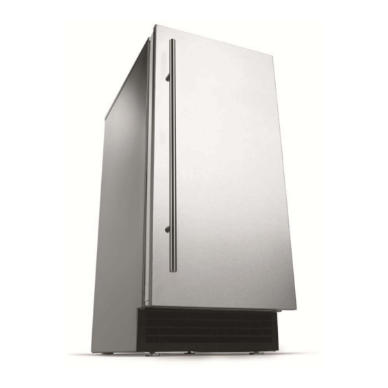
- Page 3 50 lb Models • Two Base Models – Gravity Drain – Pump Drain • 15” wide • 50 lb capacity – 50# Production – 26# Storage • Stainless cabinet with unfinished front or with a SS door (‐1SS) ...
- Page 4 30 lb Models • Two Base Models – Gravity Drain – Pump Drain • 15” wide • Capacity – 30# Production – 26# Storage • Stainless Cabinet with unfinished front only ...
- Page 5 Door Finish Details Panel Handle • All indoor models Finish Finish shipped with unfinished KDFW White White door KDFWS White Stainless – Outdoor model ships Steel with stainless steel door KDFB Black Black • Available door panel kits KDFBS Black Stainless – KDFR allows use of Steel DCE33 custom panel KDFS Stainless Stainless Steel Steel...
-
Page 6: Model Numbers
Model Numbers SCC P 50 M A -1 S U Scotsman Consumer Cuber Drain code, P = Pump, G = Gravity 30 or 50 = # of ice capacity M = Medium cube size A = Rev Level Voltage Code, -1 = 115 volt... -
Page 7: Installation
Installation • Confirm / Reverse door swing • Assemble door panel to door – Scotsman kit – Custom door – Attach panel to door with screws • Install hinge mount covers • Install hinge covers • Install hinge pin – if need to limit door opening to 90 degrees... -
Page 8: Reverse Door Swing
Reverse Door Swing • Remove hinge covers • Loosen the screw on the keyhole slot, remove the other • Pull door from unit • Switch hinges on door... - Page 9 Reverse Door Swing • Remove and replace lower door bracket – New brackets shipped loose inside the bin (wrapped in bubble wrap)
- Page 10 Reverse Door Swing • Remove top panel • Remove and replace top bracket...
-
Page 11: Installation Prep
Installation Prep • Remove front service panel • If needed, remove kickplate... - Page 12 Installation – Free Standing Gravity Drain • Route water supply tubing (copper, SS flex or PVC flex) to inlet water solenoid valve • Attach drain tubing (vinyl or rubber) to bin drain hose – Elbow and hose clamps • Route drain tubing to building drain...
- Page 13 Installation – Built In Gravity Drain • Plan the installation for machine removal – Coil of water supply tubing – Arrange the drain tubing so it does not kink when the machine is pushed into place • Recommended drain tube size is 5/8” ID, 7/8” OD plastic hose • Will connect to elbow on machine drain • Use 2‐3 foot section of 5/8” OD copper to guide drain tube into cabinet while pushing unit back • Reach back to insert elbow into hose, secure with clamp...
- Page 14 Installation – Built In Pump Drain • Remove back panel • Route water supply tubing to inlet water connection on solenoid valve • Route drain hose to building drain...
-
Page 15: Water Supply
Water Supply Route Water Supply Tubing (20 to 80 psi) ¼” Compression Fitting... -
Page 16: Door Panel
Door Panel Hole Cover • Units are shipped without door covers – Use White, Black or Stainless Scotsman panel kits • Hardware kits shipped in bin include hole covers – Make and attach a custom door panel... - Page 17 Operation – Initial Start Up • Remove shipping materials • Connect water • Check for leaks • Connect power • 50 lb: Push and release the On / Off button • 30 lb: Move rocker switch to ON...
- Page 18 50 lb Sequence of Operation – Start Up • Inlet water solenoid valve opens to fill the reservoir • Hot gas valve opens to equalize the system • Compressor, fan and pump start • Hot gas valve closes, freeze cycle begins • Freeze cycle continues until evaporator temperature reaches a preset point ‐ 0, which triggers a 10 minute (default) timer • In 10 minutes the Harvest cycle begins...
- Page 19 30 lb Sequence of Operation – Start Up • Inlet water solenoid valve opens to fill the reservoir and hot gas valve & Compressor energize to initiate harvest cycle • After 170 seconds fan and pump start and water valve & hot gas valve shut off • Freeze cycle continues until evaporator temperature reaches a preset point ‐ 0, which triggers a 6 minute (default) solid state timer • In 10 minutes the Harvest cycle begins...
- Page 20 50 lb Sequence of Operation ‐ Harvest • Hot gas valve opens • Pump and Fan motor stop • Inlet water valve opens and refills the reservoir – Fill time varies with evaporator temperature • Timed during a power restart or in clean cycle • Harvest continues – When the evaporator temperature warms to a preset point – 50, a 20 second (default) timer starts – When the time expires, harvest ends...
- Page 21 30 lb Sequence of Operation ‐ Harvest • Hot gas valve opens • Pump and Fan motor stop • Inlet water valve opens and refills the reservoir – Fill time and Harvest time controlled by timer – When the time expires (approx 3 min), harvest ends...
- Page 22 Harvest Details • SCC50: 24 individual cubes per cycle • SCC30: 12 individual cubes per cycle • DCE33: 8 individual cubes per cycle • Hot gas defrost with a water assist • Water flows onto top of evaporator platen to – Warm up the platen & obtain a faster harvest – Remove heat from the water for the next cycle which increases efficiency...
- Page 23 50 lb Control System • Electronic controller • Operates – 12 volt power supply – Compressor – Evaporator thermistor – Pump – Water quality sensor – Fan motor – Bin thermostat – Hot gas valve coil – Inlet water solenoid valve coil – Bin light...
- Page 24 30 lb Control System • Electro‐mechanical • Operates components – Compressor – Pump – On‐Off switch – Fan motor – Bin thermostat – Hot gas valve coil – Cube size thermostat – Inlet water solenoid • Electronic timer valve coil – Solid state...
- Page 25 Mechanicals No light in 30# model Curtain Bracket Fastener Curtain...
- Page 26 50 lb Controller Evaporator Thermistor Hi Voltage Connector Comp-D14 Bin Thermostat Water-D13 Water Sensor Hot Gas-D12 Fan & Pump-D11 Power Power-D5 Supply Connector Bin Light Control Panel Ribbon Cable...
- Page 27 50 lb Controls On – Off Button Used in Green when set to Blinks if out Yellow if its been 6 cleaning ice making of water months since it was process cleaned...
- Page 28 50 lb Control Operation – Check Water • Red blinking light indicates a lack of water • Water must fill reservoir within 2 minutes • Unit automatically re‐tries filling the reservoir every 20 minutes...
- Page 29 50 lb Control Defaults • Maximum freeze time: 60 minutes – Automatically harvests after 60 minutes of freeze • Maximum harvest time: 6 Minutes • Time between restarts: 4 minutes • Power interruption restart: – Timed harvest cycle to clear ice...
- Page 30 50 lb Control Details – Water Sense • Water conductivity varies by mineral content – More minerals = more conductivity • Control system senses conductivity, varies water use to rinse more water if there is high conductivity, reducing mineral build up potential • System is able to sense very clean water, such as RO water to 10 microSiemens/cm of conductivity...
- Page 31 50 lb Control Details – Ice Level • Controlled by bin thermostat in cap tube / scoop holder • When bin thermostat senses ice, contacts open, signaling controller to shut down – If suction line temperature is above preset point, unit shuts off – If suction line temperature is below preset point, unit operates until the end of the next harvest cycle, when it shuts off...
- Page 32 30 lb Control System Bin Thermostat and Cube Size Thermostat Harvest Timer...
- Page 33 Bin Thermostat Adjustment ‐ 50 lb • Adjustment screw located behind cover • Ambient compensation adjustment: – Rotate CW to raise ice level – Rotate CCW to lower ice level...
- Page 34 50 lb Top View Transformer Refrigerant Outlet Refrigerant Inlet Controller Water Inlet Evaporator Platen...
- Page 35 30 lb Top View Cube Size Water Inlet Thermostat Bulb 12 Cup Platen...
- Page 36 50 lb Mechanicals – Evaporator • 24 copper cups...
- Page 37 30 lb Mechanicals – Evaporator • 12 copper cups...
- Page 38 Water Spray – 6 Jets...
- Page 39 50 lb Back view Water Pump Water Tube Suction Line & Accumulator Compressor Bin Drain...
- Page 40 Mechanicals...
- Page 41 Mechanicals – In Reservoir Spray Platform 50 lb Water Water Inlet Sensor Probes Connection Overflow Water Pump Body Standpipe...
- Page 42 50 lb Control Operation – Time to Clean • Glowing yellow light comes on after 6 months of power up time • Cleared by going through the cleaning process or by pressing the clean reset button – Press and Hold the Clean button for 3 to 5 seconds...
-
Page 43: Maintenance
Maintenance • Air cooled condenser – service frequently when pets are in the house – Remove service panel – Remove kickplate – Vacuum condenser... - Page 44 Maintenance • Water System – Clean with scale remover – Check curtain – Check spray jet pattern • 6 jets • Platform lifts out...
- Page 45 50 lb Maintenance – Scale Remover • Remove all ice • Push and hold the On/Off button in for 3 seconds until the green light goes out • Press and HOLD the both the Clean‐Reset and On/Off buttons for 5 seconds. The Time to Clean light will blink on and off. • Pour in 8 ounces of Scotsman Scale Remover. • Operate the machine for a half hour. • Push and release the ON/OFF switch to start the rinsing process. • Operate the machine for another half hour. • Push and release ON/OFF to stop rinsing. Push ON/OFF to restart ice making.
- Page 46 Maintenance • Spray platform removable – Lift up to release platform from water inlet connection – Pull out...
- Page 47 Maintenance • Spray jet caps are removable – clean separately if needed – Remove spray platform – Remove nuts (7/32”) – Pull jet caps off...
- Page 48 Maintenance • Clear nozzle of debris • O‐ring must be in correct position and undamaged...
- Page 49 Maintenance • Optional: drain reservoir – Remove cap on bottom of reservoir – Clean cap of debris – 30# & 50# caps ARE different!
-
Page 50: Service Diagnosis
Service Diagnosis • The Recipe for Ice: – Add Water – just the right amount – Apply strong amount of Refrigeration effect to take heat from the water & release the ice – Use an Electrical System to Operate and Control the machine to deliver ice when its needed – If an ingredient is missing or out of balance, performance will suffer – and you will be called! - Page 51 50 lb Service Diagnosis – No Ice • No ice, check: – Power to unit – open door, bin light on? – Switched off – push & release ON/OFF button – Bin thermostat – contacts open? – Water in reservoir – water light blinking? • If reservoir is empty, check water supply • If there is water to the unit, check inlet water solenoid valve...
- Page 52 30 lb Service Diagnosis – No Ice • No ice, check: – Power to unit – plugged in? – Switched off – check ON/OFF switch – Bin thermostat – contacts open? – Pump model – pressure switch safety contacts open?
- Page 53 50 lb Service Diagnosis – No Ice • No ice, water in reservoir, but no spray – Check water pump • No ice, water in reservoir, sprays, ice forms but harvest cycle does not start – Check evaporator thermistor – Use ohmmeter, check resistance for the sensor’s temperature • Measure suction line temperature closest to sensor • Check chart for proper Ohm reading at that temp • Example 1 F = 82661 ohms – or use ice bath. 30 to 32K ohms at 32 degrees F.
- Page 54 30 lb Service Diagnosis – No Ice • No ice, water in reservoir, but no spray – Check water pump • No ice, water in reservoir, sprays, ice forms but harvest cycle does not start – Check cube size thermostat • Thermostat contacts close on temperature fall...
- Page 55 Service Diagnosis – Poor Cubes • Makes ice, but cubes are mal‐formed – Check for clogged / restricted spray jets – Check if running out of water before the end of the freeze cycle • Check for water leak – Clean as required...
- Page 56 Service Diagnosis – Low Capacity • Makes ice, but customer indicates low capacity – Check cycle time – 50 lb times: • 70 air, 50 water cycle time is about 20 minutes • 90 air, 70 water cycle time is about 28 minutes • 100 air, 100 water cycle time is about 45 minutes – If cycle time is long look for problem getting rid of the heat or too much heat load – Check drain • Restricted drain will cause water to back up into the storage bin and rapidly melt ice...
- Page 57 50 lb Service Diagnosis – Low Capacity • Makes ice, some cubes are malformed – Check cycle time • 21+ minute freeze • 4‐5 minute harvest • Cubes fully formed in evaporator, but are malformed when harvested • All the above indicates a low refrigerant charge...
- Page 58 Service Diagnosis – Cube Size • Makes ice, but cubes are shells – Check for shortage of water – If water supply is adequate, adjust cube size by changing freeze time • Makes ice, but cubes are too large – Freeze cycle is too long – Adjust cube size • 50 lb: Change the freeze time • 30 lb: Adjust cube size control cut in...
- Page 59 50 lb Control Adjustments – Cube Size 1. Shut unit off 2. Hold in 5 sec or until 3. Push and release to Yellow light goes out change to next level Minutes Ice making Check water Time to clean repeat as needed 4. Push and release to Default confirm the displayed 5.
- Page 60 30 lb Control Adjustments – Cube Size...
- Page 61 Service Diagnosis – Freeze Up • No ice, freezes, harvest begins but evaporator does not defrost – Hot gas valve not opening – Check coil, replace if open – Check voltage to coil, if 115 volts, and coil is not open, hot gas valve is stuck and must be replaced.
- Page 62 Service Diagnosis – Freeze Up • Freezes ice, harvest begins, fan motor stops, pump stops, water valve opens, hot gas valve opens but will not harvest all cubes – Connected to very cold water • Harvest time set too short • Adjust harvest time...
- Page 63 50 lb Control Adjustments – Harvest Time 1. Shut unit off 3. Push and release to 2. Hold in until blue light change to next level goes out Seconds Ice making Check water Time to clean 4. Push and release to Default confirm the displayed setting 5. Push and release to resume ice making ‐10 Flash...
- Page 64 30 lb Control Adjustments – Harvest Time Adjust Harvest Time Here...
-
Page 65: Clean Light
50 lb Service Diagnosis – Clean Light • Yellow Clean light is on – It’s been a long time since it was cleaned – Clean the machine per the published method, the light will go out – Or – Advise user to press and hold the clean button for 3 seconds... - Page 66 50 lb Control Operation – Manual Harvest 1. Shut unit off 2. Push and Hold in for 5 seconds, then release. • All lights flash once. 3. Wait 5 - 20 seconds • Ice Making Light switches ON 4. Push and Hold in for 5 seconds, then release. • The inlet water valve, hot gas valve and compressor will be on until harvest times out – 3 minutes. •...
-
Page 67: Refrigeration System
Refrigeration System • Normal Operating System – Suction pressure • Beginning freeze rapid pull down to: 20 PSIG • End of freeze: 1 ‐ 2 PSIG • Harvest: increases from 30 to 55 PSIG • Low charge – Suction pressure • Beginning freeze rapid pull down to: 10 PSIG • End of freeze – 2 – 3 PSIG • Harvest – slow increase from 25 to 40 PSIG... - Page 68 Service Access ‐ Remove Cabinet • Drain reservoir • Disconnect water, power and drain • Remove door‐(if preferred) Thermistor • Remove back panel Connection • Remove top panel • Remove control box cover • 50 # only‐Disconnect thermistor at controller, pull wire to back of unit • Remove curtain and hanger...
- Page 69 Service Access – Remove Cabinet • Remove evaporator water inlet Remove from here connection – Remove clip – Pull hose & elbow from inner elbow – Push inner elbow back – Rotate inner elbow up Inner Elbow – Push out of wall...
- Page 70 Service Access – Remove Cabinet • Remove service panel Air Baffle • Remove kickplate • Remove 4 bottom corner screws Bottom Corner Screw...
- Page 71 Service Access – Remove Cabinet Front Brace • Remove screws holding front braces • Separate the high voltage wire harness connectors – located by suction line • Tip evaporator & suction line assembly back enough to clear the cabinet‐Be Careful!
- Page 72 Service – Remove Cabinet • Lift cabinet off of base – Pump, bin stat and controller go with cabinet – Support evaporator Prop Tube while cabinet is off • Use 3 foot ¾” PVC tube from evaporator cube cell to base...
- Page 73 Thank you for your time and continued support of Scotsman! Let’s take a 15 min break...
Need help?
Do you have a question about the Brilliance SCCP50MA-1SU and is the answer not in the manual?
Questions and answers