Advertisement
GPS SENSOR
JLR-4340
INTRODUCTION
Thank you for choosing the JRC GPS sensor GPS124.
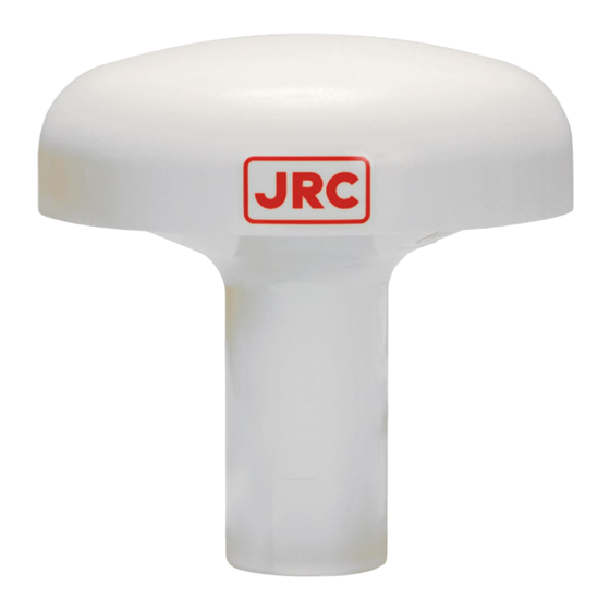
This manual describes Model GPS124, JRC GPS Sensor (Receiver) with Built-In Antenna
and SBAS capability.
• To ensure correct operation of the GPS124, please read this Instruction Manual carefully before starting
to use.
• This manual should be kept on hand to provide as quick reference whenever you need it.
• It will also help you if you come across any problems in its operation.
NOTES TO USERS
In order to ensure safe and correct use of the equipment, symbols in this manual and on
the equipment itself alert the user to important operational precautions that could prevent personal
injury or damage. The followings show such symbols and their meanings. Please read this manual
carefully and take note of these symbols.
Other Symbols and Their Meanings:
This symbol indicates that the action is prohibited.
Prohibited
This symbol indicates that the action must be taken.
Do This
CODE: 7ZPNA4008
WARNING
CAUTION
This symbol indicates warning items that, if ignored,
may result in serious personal injury or even death.
This symbol indicates cautionary items that, if ignored,
may result in personal injury or physical damage.
- 1 -
Sep. 2015 ed.6
JRC
Advertisement
Table of Contents

Subscribe to Our Youtube Channel
Summary of Contents for JRC GPS124
- Page 1 This manual describes Model GPS124, JRC GPS Sensor (Receiver) with Built-In Antenna and SBAS capability. • To ensure correct operation of the GPS124, please read this Instruction Manual carefully before starting to use. • This manual should be kept on hand to provide as quick reference whenever you need it.
-
Page 2: General Information
SECTION 1 GENERAL INFORMATION 1.1 Function By receiving GPS signals from up to twelve satellites, GPS124 sensor provides highly accurate position fixing. Furthermore, the GPS124 provides data output conforming to IEC61162-1 or the NMEA0183 format, and it can be connected to various marine equipment such as radars, fish finders, and plotters. -
Page 3: Parts And Functions
① BASE ③ CABLE ② MOUNTING SCREW 1INCH 14 UNS-2B CONNECTOR ④ CABLE LENGTH: 10m (33ft) MASS:less than 0.7kg Fig. 2-1 Parts of GPS124 DGPS Input (Brown) / 24V (Red) Set Data Input (Yellow) 5 1 6 4 Data Output 2... -
Page 4: Installation
Do not paint the outer cover of GPS124, receiver. Painting may cause poor receiving. Install the GPS124 where there is no obstacle, in order to ensure that GPS signals can be directly received from satellites without interference or reflection of signals from surrounding structures. - Page 5 3.3 Installation Procedure The base of the GPS124 is designed so that it can be installed on the navigation antenna mount unit or on an extension mast that conforms to 1” x 14 NPT standards. The bottom of the receiver is provided with a slot to allow the receiver cable to be pulled out to the side.
- Page 6 When the GPS124 is connected to directly connectable GPS navigation equipment, 12 V is supplied from the equipment to the GPS124. In this case, connect the 6-pin connector to the plug where the GPS label is attached on the rear panel of the equipment.
- Page 7 Display side 3.5 NMEA Version Switching The GPS124 has the function to switch the NMEA output versions 1.5, 2.1, and 2.3. When the equipment is shipped from the factory, the NMEA output version is set to the version 1.5. If you want to change the version to 2.1 or 2.3, please carry out the following procedure: 1.
-
Page 8: After Sales Service
Do not remove the cover of the GPS124 otherwise it may cause fire, electric shock, and malfunction. It may also cause poor waterproofing. If the GPS124 appears to be defective, check the connection again. If the equipment still appears faulty after that, stop using the equipment and contact our representative or our sales office directly. -
Page 9: Specifications
SECTION 6 SPECIFICATIONS Receiver type: Multichannel (12CH, SBAS 1CH) all in view Accuracy: 13m 2DRMS (C/A code, HDOP≦4, SA off) 7m 2DRMS (SBAS corrected) 0.1knots RMS (steady state) Geodetic datum: 46 (selectable, default : WGS-84) Data input: Initial input, GPS correction data (RTCM SC-104 ver.2.0, Type 1,2,7,9) Data output: IEC61162-1 or NMEA0183 compliance (selectable, default... - Page 10 电子信息产品有害物资申明 日本无线株式会社 Declaration on toxic & hazardous substances or elements of Electronic Information Products Japan Radio Company Limited 有毒有害物质或元素的名称及含量 (Names & Content of toxic and hazardous substances or elements ) : JLR-4340 形式名 名称 : GPS Sensor (Type) (Name) 有毒有害物质或元素 (Toxic and Hazardous Substances and Elements) 部件名称...
- Page 11 - 11 -...
- Page 12 PLACE OF CONTACT For further information,contact: Japan Radio Co.,Ltd. Since 1915 URL http://www.jrc.co.jp Marine Service Department Telephone: +81-3-3492-1305 Facsimile: +81-3-3779-1420 e-mail: tmsc@jrc.co.jp SEATTLE Branch Telephone: +1-206-654-5644 Facsimile: +1-206-654-7030 e-mail: marineservice@jrcamerica.com ALPHATRON Alphatron Marine BV URL http://www.alphatronmarine.com Rotterdam (Head office) Alphatron Marine B.V.

Need help?
Do you have a question about the GPS124 and is the answer not in the manual?
Questions and answers