Table of Contents
Advertisement
Quick Links
Advertisement
Table of Contents

Subscribe to Our Youtube Channel
Related Manuals for DOLD BI 5910


Summary of Contents for DOLD BI 5910
- Page 1 USER MAUAL Multifunction Safety Module BI 5910 with radio control 04/2007...
- Page 2 Multifunction Safety Module BI 5910 with radio control Please note here the number of your electronic key (6 figure number, engraved on the electronic key) and the Identity number of your remote control or your BI5910 Key-number: ..............Identnumber: ..............
-
Page 3: Table Of Contents
................... 13 Components of the Multifunction Safety module BI 5910 with radio control ................... 16 Configuration on delivery ................17 Multifunction Safety module with radio receiver BI 5910/00MF9 ....18 Function of BI 5910 ..................21 2.1.1 Important notes ..................... 22 Remote control .................... - Page 4 Content Auto start ....................... 26 Option start by infra-red signal (IR) ............. 27 2.8.1 Connection of infra-red sensor RE5910/060 ..........28 2.8.2 Position of infra-red sensor RE5910/060 ............ 29 Module set up ....................30 2.9.1 Configuration of receiver ................37 2.10 Operating mode 1-4 application examples ..........
- Page 5 Content Remote control RE 5910 ................73 Type and specification of push buttons ............73 Temporary disabling of function keys............74 Assignment of push buttons to outputs ............74 Identity check ....................75 Electronic key ....................76 Function activity monitoring ................78 Battery operation –...
- Page 6 LED indicators of remote control ..............94 Product specification ..................97 Remote control RE 5910 ................97 Multifunction safety module BI 5910 ............98 Standard arrangement .................. 99 Accessories – remote control RE 5910 ............. 100 Accessories – Multifunction safety module BI 5910 ......... 101...
- Page 7 Content Technical data ..................... 102 Remote control RE 5910 ................102 Multifunction safety module BI 5910 ............104 Installation notes ..................111 Disturbance protection ................111 Selection of operation frequency ............... 112 Recommendations for movement control ..........113 Position of receiver and aerial ..............114 Wiring......................
- Page 8 Content Set up ......................117 Set up directives ..................117 7.1.1 Regular check ..................... 119 Available frequencies .................. 120 Marking of function keys of remote control RE 5910 ........ 122 Accessories ....................125 Maintenance ....................126 Warranty ...................... 128...
- Page 9 Content Appendix ........................129 Front of remote control ................130 Front of receiver ..................131 Connection of receiver ................132 Dimensions ....................134 Exchange of rechargeable battery ............. 136...
-
Page 10: Application Notes
Application Notes Attention: A remote control is regarded as a control device and also as safety part because of it’s facility to switch off by the European Machinery Directive. Rules resulting from this fact have to be observed in operation. •... - Page 11 Application Notes • The operator must have full overview on all actions created by him. If the visual area of the operator is not sufficient lifting devices must be equipped with additional systems to improve the visibility. When operating several lifting devices (self moving devices) on rails they must be equipped with protective equipment to reduce the effect of collision.
- Page 12 Application Notes • If several radio controlled devices are operated in the same working area, different frequencies must be used with one channel in between (e.g. channel 5, 7, 9, …) • Due to safety reasons the electronic key must be removed when the devices are not in use.
-
Page 13: Presentation Of The Multifunction Safety Module Bi 5910 With Radio Control
1. Presentation of the Multifunction Safety module BI 5910 with radio control We thank you for selecting this Dold product. You have purchased an industrial extremely compact remote control RE 5910. The remote control can be used to control lifting devices like cranes and also for remote control of applications that have previously been wire bound or had a stationary control panel. - Page 14 1. Presentation of the Multifunction Safety module BI 5910 with radio control Main features of the multi function safety module BI 5910 • Compact device easy to install • Mounting on DIN rail • Removable terminal blocks Solutions and options to increase the application safety of the application •...
- Page 15 Presentation of the Multifunction Safety module BI 5910 with radio control This remote control is corresponding to the safety requirements of the valid or pending standards and are conform to the following European Directives: Machines, disconnection of the remote control to safety category 4, EN 954-1 RTTE Radio...
-
Page 16: With Radio Control
1.1 Components of the Multifunction Safety module BI 5910 The multifunction safety module includes: • Remote control with integrated E-stop and additional function keys • Electronic key for transmitter • Labels for marking the transmitter push buttons • Battery charger •... -
Page 17: Configuration On Delivery
1.2 Configuration on delivery Operating mode of BI 5910 Number of electronic key Rotary switch A = 0: IIndividual number generated at production - Maximum time to activate remote control and engraved on the key. after taking from charger unit 5 sec. -
Page 18: Multifunction Safety Module With Radio Receiver Bi 5910/00Mf9
2. Multifunction safety module BI 5910/00MF9 with radio control - Depending on application 1 or 2 control contacts to monitor the radio control operation • Radio receiver for: - E-stop - Control signals for 6 non-safety semiconductor outputs • Functions adjustable by rotary switches:... - Page 19 2. Multifunction safety module BI 5910/00MF9 with radio control Applications S11 S13 S11 S13 (IR) (IR) 48 S12 S14 S21 48 S12 S14 S21 13 23 31 13 23 33 A1(+) A1(+) A2(-) A2(-) 14 24 32 14 24 34...
- Page 20 2. Multifunction safety module BI 5910/00MF9 with radio control Approvals and marking * pending Anwendungen Protection of men and machines in mobile and large plants where a fixed wiring is not possible, e.g. production halls, mounting scaffolds, plants and dangerous accessible...
-
Page 21: Function Of Bi 5910
One control contact opens functions (also the hardwired ones) of the => The remote control is taken from the BI 5910 can be reset with the remote control. charger. The safety relais remain energised. Output 58 and the white LED run2 flash fast... -
Page 22: Important Notes
If an operator has to enter a dangerous area with the remote control, the machine must only run in a non dangerous speed. The BI 5910 has 2 status signals (output 58 and output17, that can be used to reduce speed and to activate a monitoring function (see 2.12) -
Page 23: Remote Control
The radio connection of the multifunction safety module to the remote control is made via an aerial that is mounted directly on the front of the BI 5910. If the unit is built into a metal cabinet the aerial has to be mounted outside. The connection is made via a special screened coax cable. -
Page 24: Safety Function
3 sec. If the BI 5910 is switched off while the remote control is active, e.g. by activating a hardwired e-stop button, the red e-stop button of the remote control has to be pressed also in order to reset the BI 5910. -
Page 25: Semiconductor Outputs
Semiconductor Connection of the outputs sensors The BI 5910 has 3 non safety semiconductor The sensors always have to be connected outputs (48, 58 and 17), that indicate the actual according to the application examples. When status of the safety module (see 2.12 indicators). -
Page 26: Manual Start And Reset
S14 and S21 to S24 can be configured used for manual start and to reset the safety for automatic start. I.e. the BI 5910 activates module. The maximum activation time of the the safety output relays as soon as the start button is 3 sec. -
Page 27: Option Start By Infra-Red Signal (Ir)
When this option is selected the receiver waits for 2 conditions before activating the safety and function outputs: 1. condition receiving a start radio message send from RE 5910 to BI 5910, 2. condition: receiving the same message via infrared that is transmitted at the same time from RE 5910 to BI 5910 while pressing the green start button. -
Page 28: Connection Of Infra-Red Sensor Re5910/060
The wiring of the IR-Module must be lead max. 2 RE 5910/061 10m long cable with separately from power lines and sources of connector the connection can be extended emission. to 30 m. Cable Connection of IR module BI 5910 Black White IR-receiver Blue RE 5910/060... -
Page 29: Position Of Infra-Red Sensor Re5910/060
2.8.2 Positioning of the IR-Module RE 5910/060 Start area (active infrared area) Max. distance see fig.3 max. distance Fig. 1 RE 5910/060 Max. distance see fig.3 Fig. 2 Fig. 3 RE 5910/060 Protection of IR-Moduls RE 5910/060: IP 65... -
Page 30: Module Set Up
Set up of safety module Platte M9409 Attention Adjustment must only be carried out The adjustment of the required functions is by trained staff while the unit is made by rotational switches, e.g. the setting disconnected from power. Before of the max. time to activate the remote opening the front of the unit potential control or the max. - Page 31 Set up of safety module Rotational switch A max. time to activate the remote control or the max. bridging time for access control rotational switch B 10 s 15 s 20 s 25 s 30 s protective devices on S11-S14 and S21-S24 always active manual start only via start button on S 42 remote control active, when one control contact on S32 or S34 is open reset of remote e-stop with remote start button...
- Page 32 Set up of safety module Rotational switch A max. time to activate the remote control or the max. bridging time for access control rotational switch B 10 s 15 s 20 s 25 s 30 s protective devices on S11-S14 and S21-S24 always active with auto start remote control active, when one control contact on S32 or S34 is open...
- Page 33 Set up of safety module Rotational switch A max. time to activate the remote control or the max. bridging time for access control Com. 10 s 15 s 20 s 25 s 30 s protective devices on S11-S14 and S21-S24 always active with manual start remote control active, when one control contact on S32 or S34 is open...
- Page 34 Set up of safety module Rotational switch A max. time to activate the remote control or the max. bridging time for access control rotational switch B 10 s 15 s 20 s 25 s 30 s monitored zone access: protective devices on S11-S14 and S21-S24 always active remote control active, when control contact on S32 is open zone protection on S21-S24 can be disabled for a specific time by remote control...
- Page 35 Set up of safety module Rotational switch A max. time to activate the remote control or the max. bridging time for access control rotational switch B 10 s 15 s 20 s 25 s 30 s monitored zone access: protective devices on S11-S14 and S21-S24 always active remote control active, when control contact on S32 is open zone protection on S21-S24 can be disabled for a specific time by remote control...
- Page 36 Set up of safety module On setting 9 when starting with open charger contact the unit can only be activated with the local start button, when the remote control has been reset and activated by its own start button. For function 8 and 9 only one charger contact is available, therefore only applications with safety category 3 are possible.
-
Page 37: Configuration Of Receiver
2.9.1 Configuration of receiver Radio frequency Factory preset is radio channel 1. A trained user with permission can change the frequency to another channel with the remote control following the programming routine (see 3.9.2). -
Page 38: Operating Mode 1-4 Application Examples
2.10 Operating modes 0-4 application examples control control E-stop 1 E-stop 2 contact 1 contact 2 start S11 S12 S14 S13 S21 S22 S24 S23 S31 S32 S34 S33 A3+ A4+ 13 BI5910 - waiting for activation failure, of remote control (waiting for start) - remote control active - failure code... - Page 39 2.10 Operating modes 0-4 application examples control control E-stop 1 E-stop 2 contact 1 contact 2 start S11 S12 S14 S13 S21 S22 S24 S23 S31 S32 S34 S33 A3+ A4+ 13 BI5910 - waiting for activation failure, of remote control (waiting for start) - remote control active - failure code...
- Page 40 2.10 Operating modes 0-4 application examples LC 1 LC 2 trans- trans- mitter mitter control control OSSD OSSD contact 1 contact 2 start S11 S12 S14 S13 S21 S22 S24 S23 S31 S32 S34 S33 A3+ A4+ 13 BI5910 - waiting for activation failure, of remote control (waiting for start)
- Page 41 2.10 Operating modes 0-4 application examples control control E-stop 1 E-stop 2 contact 1 contact 2 start S11 S12 S14 S13 S21 S22 S24 S23 S31 S32 S34 S33 A3+ A4+ 13 BI5910 - waiting for activation failure, of remote control (waiting for start) - remote control active - failure code...
-
Page 42: Function Diagrams
2.10.1 Function diagrams auxiliary supply (A1/A2) E-stop or LC 1 S12-S14 E-stop or LC 2 S22-S24 control contact 1 (S32) control contact 2 (S34) remote E-stop LED "reception" start button S42 remote start button output 17 (enabeld without radio control) relays and LEDs K1-K2 outputs 27 to 77... - Page 43 2.10.1 Function diagrams Rotational switches B=0: - Protective devices on inputs S11-S14 and S21-S24 always active, manual start only via start button on S42 - Remote control is active, when one control contact on S32 or S 34 is open. - Reset of remote e-stop with remote start button (+infra red) Adjustable monitoring time with rotational switch A max.
- Page 44 2.10.1 Function diagrams auxiliary supply (A1/A2) E-stop or LC 1 S12-S14 E-stop or LC 2 S22-S24 control contact 1 (S32) control contact 2 (S34) remote E-stop LED "reception" start button S42 remote start button output 17 (enabeld without radio control) relays and LEDs K1-K2 outputs 27 to 77...
- Page 45 2.10.1 Function diagrams Rotational switches B=1: - Protective devices on inputs S11-S14 and S21-S24 always active, manual start only via start button on S42 - Remote control is active, when the control contacts on S32 or S 34 open. -Reset of remote e-stop with start button on S42 after activating remote start button Adjustable monitoring time with rotational switch A max.
- Page 46 2.10.1 Function diagrams auxiliary supply (A1/A2) E-stop or LC 1 S12-S14 E-stop or LC 2 S22-S24 control contact 1 (S32) control contact 2 (S34) remote E-stop LED "reception" start button S42 remote start button output 17 (enabeld without radio control) relays and LEDs K1-K2 outputs 27 to 77...
- Page 47 2.10.1 Function diagrams Rotational switches B=2: - Protective devices on inputs S11-S14 and S21-S24 always active, auto start - Remote control is active, when the control contacts on S32 or S 34 open. - Reset of remote e-stop with remote start button (+infra red) Adjustable monitoring time with rotational switch A max.
- Page 48 2.10.1 Function diagrams auxiliary supply (A1/A2) E-stop or LC 1 S12-S14 E-stop or LC 2 S22-S24 control contact 1 (S32) control contact 2 (S34) remote E-stop LED "reception" start button S42 remote start button output 17 (enabeld without radio control) relays and LEDs K1-K2 outputs 27 to 77...
- Page 49 2.10.1 Function diagrams Rotational switches B=3: - Protective devices on inputs S11-S14 and S21-S24 always active, auto start - Remote control is active, when the control contacts on S32 or S 34 open. - Reset of remote e-stop with start button on S42 after activating remote start button Adjustable monitoring time with rotational switch A max.
- Page 50 2.10.1 Function diagrams auxiliary supply (A1/A2) E-stop or LC 1 S12-S14 E-stop or LC 2 S22-S24 control contact 1 (S32) control contact 2 (S34) remote E-stop LED "reception" start button S42 remote start button output 17 (enabeld without radio control) relays and LEDs K1-K2 outputs 27 to 77...
- Page 51 2.10.1 Function diagrams Rotational switches B=4: - Protective devices on inputs S11-S14 and S21-S24 always active, manual start - Remote control is active, when the control contacts on S32 or S 34 open. - Reset of all failures with start button on S42 or with remote start button (+infra red) Adjustable monitoring time with rotational switch A max.
-
Page 52: Operating Mode 8 And 9 - Monitored Zone Access
2.11 Operating modes 8 – 9 monitored zone access conveyor access, when machine stopped entry release down light barrier, door entry control panel radio entry release person with receiver remote control M9594 RE5910 The machine has an entry protected either by a light curtain or a safety gate. It may be necessary that the operator has to enter the protected area while the machine is running in order to carry out certain actions. - Page 53 2.11 Operating modes 8 – 9 monitored zone access Working principle: 3. If the remote control is acknowledged 1. As long as the remote control is in the within the required time the white LED charger station (control contact S31-S32 run2 and the output 58 turn to be con- is closed), the machine is protected by the tinnuously on.
- Page 54 2.11 Operating modes 8 – 9 monitored zone access 5. After elapse of the bridging time the pro- 7. Outside the protected area the operator tection is activated again. This state is places the remote control back into the indicated by the white LED and the out- chargaer and the control contact (S31- put 58 being continuously on.
- Page 55 2.11 Operating modes 8 – 9 monitored zone access ATTENTION As a safety gate can be connected to When using the remote control inside terminals S21 to S24 the simultaneous a machine or dangerous area, the time for the input signals has been speed of the machine must be reduced increased from 250 ms to 3 s.
-
Page 56: Application Examples
2.11.1 Application examples entry release inside transmitter outside control OSSD contact E-stop start S11 S12 S14 S13 S21 S22 S24 S23 S31 S32 S34 S33 A3+ A4+ 13 BI5910 - waiting for activation failure, of remote control (waiting for start) - remote control active - failure code M9592... - Page 57 2.11.1 Application examples entry release inside safety gate outside control contact E-stop start S11 S12 S14 S13 S21 S22 S24 S23 S31 S32 S34 S33 A3+ A4+ 13 BI5910 - waiting for activation failure, of remote control (waiting for start) - remote control active - failure code M9593...
-
Page 58: Function Diagrams
2.11.2 Function Diagrams auxiliary supply (A1/A2) E-stop or LC 1 S12-S14 gate or LC 2 S22-S24 control contact (S32) entry release (S34) remote E-stop LED "reception" start button S42 remote start button output 17 (enabeld without radio control) relays and LEDs K1-K2 outputs 27 to 77 output 58,... - Page 59 2.11.2 Function Diagrams Rotational switches B = 8: - monitored zone access, manual start - protective devices on S11-S14 always active - protective device on S21-S24 always active, when control contact on charger (S32) is closed - remote control active, when control contact on S32 is open - zone protection can be disabled for a certain time with remote control Adjustable monitoring time with rotational switch A max.
- Page 60 2.11.2 Function Diagrams auxiliary supply (A1/A2) E-stop or LC 1 S12-S14 gate or LC 2 S22-S24 control contact (S32) entry release (S34) remote E-stop LED "reception" start button S42 remote start button output 17 (enabeld without radio control) relays and LEDs K1-K2 outputs 27 to 77 output 58,...
- Page 61 2.11.2 Function Diagrams Rotational switches B = 9: - monitored zone access, manual start - protective devices on S11-S14 always active - protective device on S21-S24 always active, when control contact on charger (S32) is closed - remote control active, when control contact on S32 is open - zone protection can be disabled for a certain time with remote control Adjustable monitoring time with rotational switch A max.
-
Page 62: Indicators
2.12 Indication With the LEDs on the front side and 3 semiconductor outputs different states are indicated. flashing continuous ON green LEDs Safety relays Safety relays K1 und K2 K1 and K2 inactive K1 and K2 active - failure code: one function Control contact for does not enable the unit charger closed and... - Page 63 2.12 Indication flashing continuous ON green LEDs Safety relays Safety relays K1 und K2 K1 and K2 inactive K1 and K2 active All relays inactive All relays inactive White because of system because of system No system failure failure failure run 1 Safety outputs are de- Remote control is inactive,...
- Page 64 2.12 Indication flashing continuous ON green LEDs Safety relays Safety relays K1 und K2 K1 and K2 inactive K1 and K2 active - flashing: green LED No radio signal Bad radio signal reception Bad radio signal - symmetric flashing: Good radio signal (state radio failure in receiver unit part 2)
-
Page 65: Status And Failure Codes
2.12.1 Status and failure codes The multifunction safety module BI 5910 consists of a handling part for the complete safety functions and a handling part for the safe radio control. Therefore the failure and status indication is divided into 2 groups. - Page 66 System failures in safety operation If a system failure occurs one of the LEDs run1 or run2 is OFF or both flash with failure codes (No). The LEDS can show different failure codes at the same time. No. Description Notes and measures 1) If one pocessor detects a system failure it indicates it with the Communication failure code and interrupts the communication with the second...
- Page 67 System failures in safety operation No. Description Notes and measures 1) The feed back circuit on Y1-Y2 is not closed when safety relays are de-energised.(the feed back loop must close 50 ms after the Failure on relays de-energise relay outputs 2) One of the output relays or it’s control circuit is defective, the unit must be repaired.
- Page 68 System failures in safety operation No. Description Notes and measures The software state of the 2 parts of the unit 12 Version failure is not identically, the unit must be repaired The program memory of one processor is defective, 13 Checksum failure the unit must be repaired The work memory of one processor is defective, 14 RAM failure...
- Page 69 Status indication in safety operation A status that leads to de-energisation of the safety outputs are indicated by the white LED run2 and the output 58 with flashing code (No). The white LED run1 remains active. Output 48 is activated as long as the failure is present, it flashes symmetrically when reset by start button is possible again.
- Page 70 Status indication in safety operation No. Message Explanation - Both signals of an e-stop, light curtain or safety gate have not been operated within the required time. Both signals must now be disconnected before a new start is possible. Simultaneity - The entry release button or the start button on the remote control failure have been operated to long.
- Page 71 Failure and status indication of the radio receiver The status of the safety radio receiver is indicated by flashing codes (No) of the red LED ”receiver error” and the green LED “reception”. Red LED “receiver error” Status Mode Description No radio signal Message with valid identity code Normal operation Symmetric...
- Page 72 Failure and status indication of the radio receiver Green LED “reception” Status Mode Description No radio signal Symmetric flashing Normal operation Bad radio connection Good radio connection Serial Writing parameters and reading data connection Supply Sicherheitsverbindung zum Verwaltungsteil Flashing with EEPROM Error failure code...
-
Page 73: Remote Control Re 5910
Type and specification Remote control of push buttons RE 5910 The remote control is available with 5 different types of buttons: 1-position push button (BPSV) 2-position push button (BPDV) rotational switch with 2 positions (COM2) rotational switch with 3 positions (COM3) rotational switch auto resetting with 3 positions (COM3R) -
Page 74: Temporary Disabling Of Function Keys
Assignment of push Temporary disabling buttons to outputs of function keys The function key can be temporary disabled The semiconductor outputs are assigned to in pairs. the push buttons as follows: 1. button 2. button Button Output Remote control Abbreviation pair pair with 1-position... -
Page 75: Identity Check
- The identity code of the RE 5910 is stored on an electronic key and on the remote control - The identity code of the BI 5910 is individual and cannot be modified, it is set in the factory. There are 65536 different combinations for an identity code. -
Page 76: Electronic Key
( 4 flash code) and a passive disconnection of the BI 5910 multifunction safety module follows. (can only be reset by switching off and on the power supply of the unit.) - Page 77 Electronic key Defective remote control Identity code stored RE 5910 in remote control RE 5910 It is possible to take the key from an defective remote control and put it to a spare one with the same push buttons as on the defective one. If the buttons are different they cannot be operated.
-
Page 78: Function Activity Monitoring
Function activity monitoring While activity monitoring is selected the remote control will be deactivated (interruption of radio signal) if within the programmed interval N in seconds or minutes no push button is activated. The time N and the time unit (sec, min) can be adjusted by the operator. N can be 1 to 98 minutes or 1 to 99 seconds. -
Page 79: Battery Operation - Storage Rules For Remote Control Re 5910
Battery operation – 3.7.2 Indication of storage recommendations charging level The remote control RE 5910 has to be On the remote control there are 2 possibilities stocked with charged battery. to indicate the charging state: - When activating the remote control (release of e-stop button) the red LED shows the 3.7.1 Charge battery state of the battery:... -
Page 80: Power Up Remote Control
When the remote control is taken from the charger the control contacts open and indicate to the BI 5910 that the remote control is now on operation. If the safety contacts are already active the BI 5910 waits for the period of time adjusted with the rotational switches that the radio transmission get active. - Page 81 3.8.1 Function Diagrams release of red aktivation of e-stop button green start Last operation of a function key Operation activation RE5910 button aktiv 3 states of (1) time interval for standby RE5910 activity monitoring multifunction safety module BI5910 with radio control green LED RE5910 red LED of RE5910/060...
-
Page 82: Configuration Of Remote Control
Configuration of remote control The following parameters can be set on the remote control: - Transmission frequency, selection of channel 01 – 64 - Time interval for activity monitoring 0-99 sec or 0-98 min or infinite (99 min) - transfer of identity code from electronic key to the remote control By a special procedure a trained and authorised person can disable or enable the above functions. -
Page 83: Disabling - Enabling Of Remote Control Programming
3.9.1 „Enabling-disabling“ of remote control programming 1. Disconnect the multifunction safety module BI 5910 with radio control 2. Insert the electronic key into the remote control 3. Keep the buttons B1,B2 and the green start button pressed - release the e-stop button (pic.1),... - Page 84 3.9.1 „Enabling-disabling“ of remote control programming Enabling Disabling RE 5910 RE 5910 RE 5910 pic. 1 pic. 2 pic. 3 RE 5910 RE 5910 Electronic key pic. 4 pic. 5 pic. 6...
-
Page 85: Programming Of Frequency
3.9.2 Programming of radio frequency 1. Disconnect the multifunction safety module BI 5910 with radio control 2. Insert the electronic key into the remote control 3. Keep the buttons B1,B2 pressed - release the e-stop button (pic.1), - release buttons B1, B2 The flashing LEDs indicate the actual selected channel. - Page 86 3.9.2 Programming of radio frequency Short activation of start The remote control sends the new channel number to the BI 5910 and stores the new working frequency (pic.5). Long activation of start (3 sec) The remote control sends the new channel number to the BI 5910 on all radio channels and stores the new working frequency, please wait until the flashing of the LEDs stops (approx.
- Page 87 3.9.2 Programming of radio frequency RE 5910 RE 5910 RE 5910 pic. 1 pic. 2 pic. 3 RE 5910 RE 5910 pic. 4 pic. 5 pic. 6...
- Page 88 1. The time base i.e. seconds or minutes 2. The time interval 3.9.3.1 Programming of time base – activity monitoring 1. Disconnect the multifunction safety module BI 5910 with radio control. 2. Insert the electronic key into the remote control. 3. Keep the button B1 pressed, - Release the e-stop button (pic.1),...
- Page 89 3.9.3.1 Programming of time base – activity monitoring RE 5910 RE 5910 min/s pic. 1 pic. 2 RE 5910 RE 5910 Electronic key pic. 3 pic. 4 pic. 5...
- Page 90 3.9.3.2 Programming of the time period – activity monitoring 1. Disconnect the multifunction safety module BI 5910 with radio control 2. Insert the electronic key into the remote control 3. Keep the buttons B1and start pressed 4. Release the e-stop button (pic.1) 5.
- Page 91 3.9.3.2 Programming of the time period – activity monitoring RE 5910 RE 5910 RE 5910 min/s min/s pic. 1 pic. 2 pic. 3 RE 5910 RE 5910 Electronic key pic. 4 pic. 5 pic. 6...
-
Page 92: Copy Of Identity Code From Electronic Key To Remote Control Re 5910
RE 5910 Please follow this instruction if a maintenance 1. Disconnect the multifunction safety module remote control should be used, or the BI 5910 with radio control electronic key has been exchanged. 2. Insert the electronic key into the remote control Note: 3. - Page 93 3.9.4 Copy of identity code from electronic key to remote control RE 5910 RE 5910 RE5910 RE 5910 Electronic key RE5910 Schlüsselspeicher Memory of the RE 5910 pic. 2 pic. 1 pic. 3 RE 5910 RE5910 pic. 4...
- Page 94 3.10 LED indicators of the remote control Status Red LED Green LED Function Switched OFF or time of Before or after „ON“ activity monitoring exceeded or RESET with discharged battery Before „ON“ Battery charge > 50% Before „ON“ Slow flashing 50% >...
- Page 95 3.10 LED indicators of the remote control Status Red LED Green LED Function Before or after „ON“ 4 flashes 4 flashes Push button defective Error at activation or Before „ON“ deactivation detected. 5 flashes 5 flashes Please observe starting conditions under 3.8 Error at activation or deactivation detected.
- Page 96 3.10 LED indicators of the remote control Status Red LED Green LED Function Config.mode: Remote control disabled Disabling - Enabling Config.mode: Remote control enabled Disabling - Enabling Quick charge process (operated by Battery charging Flashing (microprocessor of RE5910) Slow charging or charge conservation Battery charging (operated by microprocessor...
-
Page 97: Product Specification
Product specification Remote control RE 5910 The model of the remote control is defined with a 10 figure type number: RE 5910/00_ Variant 4 x 2 step push buttons, without IR, with electronic key 4 x 2 step push buttons, with IR, with electronic key 4 x 1 step push buttons, without IR, with electronic key 4 x 1 step push buttons, with IR, with electronic key 5: B1-B3: step push button (BPSV),... -
Page 98: Multifunction Safety Module Bi 5910
Multifunction safety module BI 5910 with radio control The model of the multifunction safety module BI 5910 with radio control is defined with a 14 figure type number: BI 5910._ _/0_MF9 DC 24 V Option start with infra red without IR start... -
Page 99: Standard Arrangement
Standard arrangement The standard arrangement consists of the following components: • 1 Receiver BI 5910.03/01MF9 • 1 Infra red receiver with 10 m wire RE 5910/060 • 1 Remote control + 1 electronic key RE 5910/002 • 1 Aerial RE 5910/040 •... -
Page 100: Accessories – Remote Control Re 5910
Accessories – remote control RE 5910 RE 5910/010 Industriel charger unit RE 5910/011 Power supply for charger AC 230V (Euro connector) RE 5910/012 Power supply for charger DC 12/24 V RE 5910/020 Green electronic key with program RE 5910/021 Orange electronic key with program Important: Please state the following details on order: •... -
Page 101: Accessories – Multifunction Safety Module Bi 5910
Accessories Multifunction safety module BI 5910 RE 5910/040 Straight 1/4 aerial 433-434 MHZ – BNC λ RE 5910/041 Straight 1/2 aerial 433-434 MHZ – BNC λ RE 5910/042 2 m Extension for aerial + enclosure fixture –BNC RE 5910/043 5 m Extension for aerial + enclosure fixture –BNC... -
Page 102: Technical Data
Technical data Remote control RE 5910 Enclosure Material: Degree of protection: IP65 Ambient temperature: -20°C ... +50°C Holder for non-operation: Charger unit Weight (with battery): 240 g Dimensions: 46 x 78 x 143 mm Radio Conformity: ETS 300 220 Carrier frequency: UHF, frequency modulated (FM) Frequency: 64 programmable frequencies... - Page 103 Technical data Remote control RE 5910 Battery Type: NiMH Charge/discharge cycles: min. 500 cycles Charging time: 2 h, at 20°C (80%) (for completely discharged battery) Full charging time: 2 h 30 min (100%) Charge capacity Normal operation of push buttons: 20 h at 50% operation, +20°C after 10 minutes charging of discharged battery: approx.
-
Page 104: Multifunction Safety Module Bi 5910
Technical data Multifunction safety module BI 5910 Radio Conformity: ETS 300 220 Aerial: 1/4 aerial, plug in as accessory Frequency: 64 programmable frequencies 433.1 … 434.675 MHz Sensitivity: < -100 dBm Nominal voltage U DC 24 V Voltage range: at max. 5 % residual ripple: 0,85... 1,15 U Nominal consumption: max. - Page 105 Technical data Multifunction safety module BI 5910 Fusing: Internal with PTC Max. time difference between input signals of one function E-stop, Light curtains: 250 ms Gates: Safety Output Contacts BI 5910.03: 3 NO contacts BI 5910.22: 2 NO contacts, 1 NC contact...
- Page 106 Technical data Multifunction safety module BI 5910 Switching off time (reaction time) S12-S14, S22-S24, S32-S34: max. 25 ms E-stop (Radio): max. 170 ms Passive disconnection because of interrupted radio signal: max. 500ms Disconnection with active radio signal and closed charge control contact: max.
- Page 107 Technical data Multifunction safety module BI 5910 to AC 15 at 2 A, AC 230 V: 100000 switching cycles IEC/EN 60 947-5-1 Permissible switching frequence: max. 1200 switching cycles / h Short circuit strength max. fuse rating: 6 A gL...
- Page 108 Multifunction safety module BI 5910 Circuit Diagrams I (A ) ° T ( C) M9422 Quadratischer Summenstrom I = I + I + I Schaltstrom I I , I , I - Strom in den Kontaktpfaden Sicheres Abschalten, kein stehender Lichtbogen unterhalb der Kurve, max.
- Page 109 Technical data Multifunction safety module BI 5910 General Data Operating mode: Continuous operation Temperature range: 0 ... 50°C Clearance and creepage dist. overvoltage category / contamination level: 4 kV / 2 IEC 60 664-1 HF- irradiation: 10 V / m...
- Page 110 Technical data Multifunction safety module BI 5910 Vibration resistance: according to EN 61496-1 (1997) Amplitude 0,35 mm IEC/EN 60 068-2-6 frequency 10 ... 55 Hz Shock proof Acceleration: Impulse length: 16 ms Number of shocks: 1000 per ax is on all 3 axes...
-
Page 111: Installation Notes
- Selection of operating frequency, - Help on movement control, - Location of BI 5910 and aerial, - Careful wiring of BI 5910 and the connected systems, - Protection of the electric supply, - Min. and max. switching current of the different outputs... - Page 112 Selection of the operating frequency The 64 radio channels offer a wide selection within the frequency band. For a good operation quality it is necessary to make sure that the selected frequency channel is not used by other equipment in the working area. If several remote controls are used in the same location no neighbour channels must be used.
- Page 113 Recommendations for motion control If several lifting devices with hanging load are equipped with remote controls and work near to each other (e.g. in a production hall) each remote control must be clearly marked to indicate which load is controlled by which remote control. For this purpose coloured arrows can be used to mark the equipment and the corresponding pushbutton on the remote control.
- Page 114 The multifunction safety module with radio control must be installed as near as possible to or inside the control cabinet. The BI 5910 must be protected against shocks an weather influences The aerial must be installed outside the cabinet and in max possible distance to class 3 wires and load equipment (power supplies, motors, inverters) and in an area that is useful for a radio receiver.
-
Page 115: Wiring
Attention: The electrical connection of the power supply must be installed in a way that with de- activation of the main power switch also the BI 5910 is de-activated. Make sure, that no inductances are created by wiring the charger that could damp the radio signal of the remote control when it is put into the charger. -
Page 116: Protection Of Power Supply
Protection of power supply Protection against overcurrent resulting from Overvoltage (EN 0204-1, § 7.2) The power supply of the multifunction safety module BI 5910 with radio control is protected with an internal PTC. Minimum and maximum output current Please make sure, that the minimum and maximum values stated under 5.2 are not exceeded. -
Page 117: Set Up Directives
• Before installation and testing please charge the unit for 24 hours (see 3.7.2). • Please check that identity codes and radio channels are identically on RE 5910 and BI 5910 • Check if the selected radio channel corresponds to the generated frequency plan •... - Page 118 Set up Set up directives • In infra red start mode please evaluate and check the range of the radio control, that it is limited to the area defined for this application • Evaluate and check the limits for radio control by operating it in all different areas of the application.
-
Page 119: Regular Check
Set up 7.1.1 Regular checking In addition to the tests during set up in regular intervals and after all maintenance work the following test have to be made: • The mechanical function of the remote control i.e. the function of the push buttons, activation of e-stop button etc. -
Page 120: Available Frequencies
Table of available frequencies: If several remote controls are used in the same local area different radio channels have to be used for transmission with at least one free channel between two active channels (e.g. channel 5, 7, 9, …) Range 433-434 MHz distance between channels 0.025 MHz Channel Frequency... - Page 121 Table of available frequencies: Channel Frequency Channel Frequency Channel Frequency 433.925 (1) (2) 434.200 434.475 433.950 434.225 434.500 433.975 (1) (2) 434.250 434.525 434.000 434.275 434.550 434.025 (1) (2) 434.300 434.575 434.050 434.325 434.600 434.075 434.350 434.625 434.100 434.375 434.650 434.125 434.400 434.675...
- Page 122 9. Marking of function keys on the remote control RE 5910 Marking is made on self adhesive stickers that RE 5910/030 RE5910/030 can be fixed on the remote control in especially Set with 6-colour stickers “movements” for designed positions. 2 step push buttons (2 marking areas) The stickers are delivered on sheets from which the operator selects the required stickers.
- Page 123 9. Marking of function keys on the remote control RE 5910 RE 5910/031 Set with 90 black and white stickers...
- Page 124 9. Marking of function keys on the remote control RE 5910 RE 5910/033 Set with 48 unlabeled (white) stickers and 48 transparent protection stickers for idividual labelling...
-
Page 125: Accessories
Material: leather, with rings to clip in the personal mounting harness RE 5910/071. metal clip to fix it on belt. RE 5910/071: Personal mounting harness with elastic straps to carry the remote control BI 5910/001 or BI5910/002 in the holster RE5910/070 on the body of the operator. -
Page 126: Maintenance
Maintenance Maintenance of the remote control RE 5910 This remote control needs a minimum of maintenance Attention: Disconnect the power supply of the controlled system before starting maintenance Every 3 months check the correct state of the remote control and inspect especially the seals of the push buttons and the electronic key. - Page 127 Maintenance of the multifunction safety module BI 5910 with radio control Please check the following points: • The wiring of BI 5910 with the circuits of the controlled machine • The correct function of active and passive disconnection • Seal of aerial •...
-
Page 128: Warranty
Safety remarks, limitation of liability and warranty Safety remarks SAFEMASTER W must only be installed and set up by authorised and skilled persons : - Who are trained for correct treatment of safety components, - Who are familiar with the relevant standards for safety on work and protection against accidents, and have read and understood this user manual. -
Page 129: Appendix
Appendix... -
Page 130: A Front Of Remote Control
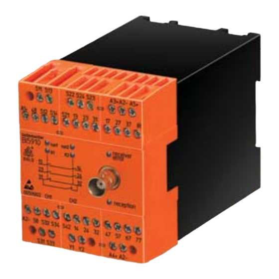
Appendix A Front of remote control RE 5910 RE 5910 Function sticker Buttons row 2 Function keys B1-B4 Buttons row 1 Green button „start“ Red LED Electronic key „Status of battery +indication“ Green LED „ON + indication“ E-stop button Clip on ring for neck holder or belt clip... - Page 131 Appendix B Front of multifunction safety module BI 5910 with radio control position marking of terminal blocks Removable terminal block Red LED „receiver error“ status of BI 5910 White status LEDs „run 1“ and „run 2“ 2 green LEDs: BNC-connector for aerial...
-
Page 132: B Connection Of Receiver
Appendix Connection of receiver BI 5910 Terminals Inputs and Terminals Inputs and safety outputs safety outputs DC 24 V supply voltage S33/S34 2. control input for for safety module charger unit Common ground input for hard wired 48/58 Semiconductor outputs 24 V:... - Page 133 Appendix B Connection of receiver BI 5910 Terminals semiconductor outputs Terminals semiconductor outputs assigned to remote control assigned to remote control DC 24 V supply for Voltage output DC 12V semiconductor outputs Input signal Common ground Common ground Start without remote control B1, 1.
-
Page 134: C Dimensions
Appendix Dimensions RE 5910 Remote control RE 5910 IR- module RE 5910/060... - Page 135 Appendix Dimensions RE 5910 RE 5910/011 (AC 230 V) RE 5910/012 (DC 24 V) Industriel charger unit RE 5910/010...
-
Page 136: D Exchange Of Rechargeable Battery
Appendix Exchange of rechargeable battery Attention opened enclosure Battery Change battery only in a place that connector is protected against electrostatic discharge (e.g. use of antistatic bracelets) to avoid damage of electronic components of the remote control. Battery 1. Switch off the corresponding multi function Battery cable safety module with radio control 2. - Page 137 Appendix Exchange of rechargeable battery 6. Remove old defective battery 7. Connect new battery 8. Check position of battery it must fit properly into the cover 9. Please check cleanness of seal and enclosure and close the unit, do not squeeze battery cable 10.
- Page 138 Notes ________________________________________________________________________ ________________________________________________________________________ ________________________________________________________________________ ________________________________________________________________________ ________________________________________________________________________ ________________________________________________________________________ ________________________________________________________________________ ________________________________________________________________________ ________________________________________________________________________ ________________________________________________________________________ ________________________________________________________________________ ________________________________________________________________________ ________________________________________________________________________ ________________________________________________________________________ ________________________________________________________________________...
- Page 139 Notes ________________________________________________________________________ ________________________________________________________________________ ________________________________________________________________________ ________________________________________________________________________ ________________________________________________________________________ ________________________________________________________________________ ________________________________________________________________________ ________________________________________________________________________ ________________________________________________________________________ ________________________________________________________________________ ________________________________________________________________________ ________________________________________________________________________ ________________________________________________________________________ ________________________________________________________________________ ________________________________________________________________________...
- Page 140 E. Dold & Söhne KG Postfach 12 51 D-78150 Furtwangen Telefon: 0 77 23 / 654-0 Telefax: 0 77 23 / 654-356 e-mail: dold-relays@dold.com internet: http://www.dold.com...
Need help?
Do you have a question about the BI 5910 and is the answer not in the manual?
Questions and answers