Table of Contents

Related Manuals for Rheem W2W Series


Summary of Contents for Rheem W2W Series
- Page 1 Owners Guide Installation Instructions Commercial Water to Water Heat Pump Water Heater WMKA21549 This water heater must be installed and serviced by an qualified person. Please leave this guide with a responsible officer.
- Page 2 Compliance Certificate. PATENTS This water heater may be protected by one or more patents or registered designs. ® Registered trademark of Rheem Australia Pty Ltd. ™ Trademark of Rheem Australia Pty Ltd.
-
Page 3: Table Of Contents
Heat Pump And Tank Assembly ..........31 Manifold Installations ..............35 Connections – Plumbing ............38 Commissioning ................56 Draining The Water Heater ............68 TROUBLE SHOOTING ............... 68 Rheem Heat Pump Water Heater Warranty - Australia & New Zealand Only - ................70... -
Page 4: About Your Water Heater
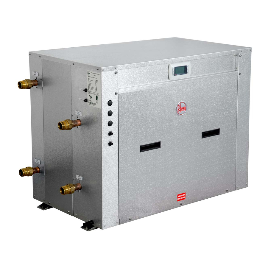
MODEL TYPE ® Congratulations for choosing a Rheem commercial water to water (W2W) heat pump water heater. The Rheem W2W heat pump water heater is designed for outdoor or indoor installation. HOW HOT SHOULD THE WATER BE? minimum recommended... - Page 5 415V / 240 V wiring. They must only be removed by a qualified person. SAFETY This water heater is supplied with built in Rheem IQ Controller which controls low and high pressure switches, low temperature cut off, temperature safety switch and flow switch.
- Page 6 ABOUT YOUR WATER HEATER TO TURN OFF THE WATER HEATER Switch off the electrical supply at the isolating switch to the water heater Close the cold side and hot side water isolation valve at the inlets to the water heater.
- Page 7 The refrigerant must not be vented to atmosphere. Phone your nearest Rheem Service Department or Accredited Service Agent (or Service Centre in NZ) to arrange for an inspection.
-
Page 8: How Your Water Heater Works
12C and maximum of 35°C. Operation with higher cold side inlet temperature is possible, however must be engineered in consultation with Rheem. The efficiency of the water heater is relative to the building chilled water circuit temperature and the incoming hot side (potable) water temperature. - Page 9 HOW YOUR WATER HEATER WORKS To prevent this damage, the pumps for both sides of the water heater are sized and supplied by Rheem and the heat pump is supplied with a flow switch sensor and a low temperature cut out switch.
- Page 10 The auxiliary boost will remain active until the water heater fault is cleared. Warning: Rheem will not be responsible for higher utility bills due to excessive use of auxiliary boost heater. It is the customers’ responsibly to monitor the system regularly for its correct operation. Rheem recommends monitoring via BMS (modules supplied separately).
- Page 11 The output of these sensors are displayed on the user friendly control panel to ensure correct system operation. The system can be connected to BMS via interface cards (Modbus RS485 or BACnet MS-TP or BACnet Ethernet) supplied by Rheem. Contact Rheem for further information on BMS.
-
Page 12: Regular Care
REGULAR CARE It is suggested that the commercial heat pump be serviced annually, to retain optimum performance. Servicing must be performed by a suitably qualified person. Annual Service Check for leaks at all fittings. Check for signs of excessive corrosion on storage tank(s) jacket(s) and heat pump casing. - Page 13 If water does not flow freely from the drain line when the lever is lifted, then the water heater must be checked Phone Rheem Service or their nearest Accredited Service Agent (or Service Centre in NZ) to arrange for an inspection.
-
Page 14: Water Supplies
Where the saturation index is less than –1.0, the water is very corrosive and the Rheem warranty does not apply to the water heater. In a corrosive water supply, the water can attack copper parts and cause them to fail. - Page 15 WATER SUPPLIES Where the pH is less than 6.0 the Rheem warranty does not apply to the water heater. pH is a measure of whether the water is alkaline or acid. In an acidic water supply, the water can attack stainless steel parts and cause them to fail.
-
Page 16: Save A Service Call
Is the alarm light flashing RED on heat pump controller? If the alarm light is flashing RED, check the alarm by pressing the alarm button. Phone your nearest Rheem Service Department or Accredited Service Agent (or Service Centre in NZ) to inform about the alarm. - Page 17 Water heater size Do you have the correct size water heater for your requirements? The sizing guide in the sales literature and on the Rheem website (www.rheem.com.au or www.rheem.co.nz) suggest average sizes that may be needed. WATER TOO HOT...
- Page 18 Heat pump circulator has failed If the heat pump circulator has failed, the heat pump will not operate. Phone your nearest Rheem Service Department or Accredited Service Agent (or Service Centre in NZ) to arrange for an inspection. HIGH ELECTRICITY BILLS With the installation of your new water sourced heat pump water heater, maximum electrical energy savings can be achieved.
-
Page 19: Installation
INSTALLATION THIS WATER HEATER IS FOR INDOOR OR OUTDOOR INSTALLATION. THIS WATER HEATER IS NOT SUITABLE FOR POOL HEATING. INSTALLATION STANDARDS The water heater must be installed: by a qualified person, and in accordance with the installation instructions, and ... - Page 20 INSTALLATION WATER HEATER LOCATION All models are designed to be installed outdoors or indoors, as long as the room meets the volume requirements stated above. It is advisable to install the water heater away from bedroom or living room windows as the system can generate a noise of 59dBA (at 3 metres from the water heater) whilst operating.
- Page 21 INSTALLATION MAINS WATER SUPPLY Where the mains water supply pressure exceeds that shown in the table below, an approved pressure limiting valve is required and should be fitted as shown in the installation diagram (refer to diagram on page 38). Relief valve setting (VE/610 Series storage tanks) 1000 kPa Expansion control valve setting *...
- Page 22 A temperature limiting device cannot be installed in circulated hot water flow and return pipe work unless the device is designed for such application, such as Rheem Guardian. The tempered water from a temperature limiting device cannot be circulated. Where a circulated hot water flow and return system is required in a building, a temperature limiting device can only be installed on a dead leg, branching off the circulated hot water flow and return pipe.
- Page 23 These circuits are in close proximity to the jacket and rupturing of the circuit may occur. Note: If the heat pump is damaged as a result of attaching pipe clips or saddling to the jacket, any resultant faults will not be covered by the Rheem warranty.
- Page 24 INSTALLATION Typical Installation with Recirculation...
- Page 25 INSTALLATION Typical Installation with Inline Auxiliary Boost...
- Page 26 INSTALLATION Typical Installation with Rheem Guardian Warm Water System...
- Page 27 INSTALLATION Dimensions and Technical Data - RHEEM W2W Model 15kW 95401500...
- Page 28 INSTALLATION Dimensions and Technical Data - RHEEM W2W Model 35kW 95403500...
- Page 29 INSTALLATION Dimensions and Technical Data - RHEEM W2W Stackable Model 15kW 9540150S...
- Page 30 INSTALLATION Dimensions and Technical Data - RHEEM W2W Stackable Model 35kW 9540350S...
-
Page 31: Heat Pump And Tank Assembly
CLEARANCES- WATER TO WATER HEAT PUMP MODELS Sides Unit All Water to Water Heat Pumps Front Back Water Connections Side RHS Side Top (clearance above unit required for service personnel to stand) HEAT PUMP AND TANK ASSEMBLY HEAT PUMP AND STORAGE TANKS The heat pump water heater system is modular and comprises three main components: the heat pump water heater, storage tanks, and primary circulators. - Page 32 Items 3 to 6 in the table below are supplied with a stackable heat pump model. Note: Top unit can be 9540**00. STORAGE TANKS Rheem Commercial storage tanks are employed to store the hot water generated ® by the heat pump. The tanks must be manifolded using the Equa-Flow manifold system to ensure even distribution of the stored energy.
- Page 33 The designed primary pump per 15kW model is Grundfos CM3-2 and per 35kW model is CM10-1. Refer to installation manuals supplied with pumps. If another pump has been supplied, consult Rheem before continuing with the installation. Header pipe sizing is based on one pump per heat pump with a total length of...
- Page 34 HEAT PUMP AND TANK ASSEMBLY AUXILIARY WATER HEATER It may be necessary to install an auxiliary water heater under the following conditions: If poor flow rate is sensed or the cold side outlet temperature or hot side outlet temperature is likely to drop below 5 C during periods when heating may be required.
-
Page 35: Manifold Installations
MANIFOLD INSTALLATIONS The Rheem commercial heat pump water heater is designed to be installed with storage tanks on a single manifold, or multiple manifolds if required, using the ® Rheem Equa-Flow manifold system. The Equa-Flow principle will function with water heaters in line, around a corner or in rows back to back (refer to the diagrams on pages 36 to 37). - Page 36 MANIFOLD INSTALLATIONS Manifold Arrangement HOT WATER FLOW Hot Manifold Assembly RETURN FROM HEAT PUMPS Primary Hot Water Flow Manifold Assembly FLOW TO HEAT PUMPS Cold Manifold Assembly...
- Page 37 1250 1000 2100 1000 RT2000 1550 1300 2700 1300 RT3000 1700 1450 3000 1450 RT4000 1850 1600 3300 1600 RT5000 2050 1800 3700 1800 Back to Back Manifold INSTALLATION LAYOUT MINIMUM DIMENSIONS INSTALLATION DIMENSIONS – MULTIPLE RHEEM STORAGE TANKS MODEL...
-
Page 38: Connections - Plumbing
CONNECTIONS – PLUMBING CONNECTION SIZES Model 15kW 35kW Heat pump water heater inlet connection R1¼ BSPM R2 BSPM Heat pump water heater outlet connection R1¼ BSPM R2 BSPM Condensate drain connection 20mm O.D All plumbing work must be carried out by a qualified person and in accordance with the Plumbing Standard AS/NZS 3500.4 and local authority requirements. - Page 39 CONNECTIONS - PLUMBING RELIEF VALVE The heat pump is supplied with an integral pressure relief valve located on the inside of the heat pump cabinet and will discharge into the tray of the heat pump. Refer to Condensate Drain on page 39 for drainage instructions. EXPANSION CONTROL VALVE Local regulations may make it mandatory to install an expansion control valve (ECV) in the cold water line to the water heater system.
- Page 40 CONNECTIONS – ELECTRICAL The power supply to the water heater must not be switched on until the water heater is filled with water and a satisfactory megger reading is obtained. MEGGER READING When a megger test is conducted on this water heater, then the following should be noted.
- Page 41 Photo inside each pump cover Hot Side and Cold Side Pumps The power to the hot side pump and cold side pump for each heat pump is supplied from the water heater (heat pump enclosure). Connect the active, neutral and earth wire to each pump terminals as shown in the photo inside the pump cover and to the terminals located within the heat pump electrical...
- Page 42 For RT series tanks, a thermostat well is supplied which needs to be fitted to the fitting (2 from the bottom) as shown. Fit sensor well here For 610 series tanks, remove the plastic cover from the fitting located 90 from the water connections on the storage tank, but do not discard.
- Page 43 Depending on the installation, an auxiliary boost element may be supplied with an RT series storage tank. If a single auxiliary boost element is supplied by Rheem, remove bridging wire at the terminals marked ‘A7 and A9’ behind the element controller cover and connect the terminal A7 and A9 to the voltage free terminal marked ‘VF’...
- Page 44 CONNECTIONS - ELECTRICAL Picture of heat pump terminal strip showing VF connections Where multiple auxiliary boost elements are required, and the number of auxiliary boost elements matches the number of heat pumps, each element may be interlocked with an individual heat pump directly using the method described above.
- Page 45 CONNECTIONS - ELECTRICAL Multiple Heat Pump Installation Up to four heat pumps can be interconnected by daisy chaining the LAN cables for operation as shown below. LAN cable is available as an accessory (part number: 17534). Step 1: Heat Pump Heat Pump- Master Heat Pump Heat Pump...
- Page 46 CONNECTIONS - ELECTRICAL heat pump enclosure: Connect “DI4” with “DIC1”. Connect “DIC1” with the existing wire as shown in the picture. heat pump enclosure: Connect “DI3” with “DI4” and “DIC1”. Connect “DIC1” with the existing wire as shown in the picture.
- Page 47 (Modbus or BACnet), available as an accessory. Based on site requirement, a suitable interface card needs to be connected to Rheem IQ control panel as shown in the diagram below. If the system is comprised of single or multiple standalone heat pumps, each heat pump will have its own BMS card.
- Page 48 15KW HEAT PUMP INTERNAL WIRING DIAGRAM...
- Page 49 CONNECTIONS - ELECTRICAL 35KW HEAT PUMP INTERNAL WIRING DIAGRAM...
- Page 50 CONNECTIONS - ELECTRICAL Controller and Display Information...
- Page 51 Note: If no keys are pressed for 60 seconds, screen reverts to main display screen and any changes made and not confirmed will be lost. Set Point Quick Setting Press ‘prg’ from the main display screen and the Set Point page will appear. Cursor will be on the set temperature.
- Page 52 CONNECTIONS - ELECTRICAL Enabling Scheduler to ‘Yes’ will open a 2 page which will allow the user to program specified operating times on a 7-day basis. E.g.: Clock Schedule Mon 00:00 to 00:00 Tue 00:00 to 00:00 Pressing the ‘down’ key will reveal a 2 page in the Clock Scheduler: –...
- Page 53 CONNECTIONS - ELECTRICAL D. Input/output View – Displays the actual readings as follows: Hot Enter Temp: Potable water temperature entering and leaving the condenser heat exchanger (A2W and W2W Hot Leave Temp: heat pumps) Cold enter Temp: Non-potable/chilled water temperature entering and leaving the evaporator heat exchanger Cold Leave Temp: (W2W heat pump)
- Page 54 CONNECTIONS - ELECTRICAL E. Alarm History – will display up to 150 alarm events and then will overwrite oldest event. Alarms can be cleared by pressing the ‘Alarm Bell’ key. F. Service – password: 0022 Change display (do not use) Information –...
- Page 55 CONNECTIONS - ELECTRICAL Service Settings Working Hour Set Prove Adjustment Thermoregulation (for multiple heat pump installation, change the no. of compressor and other settings from here.) f. Service Settings Screen Parameter Sub Parameter Master Slave Setpoint 60.0°C Screen N/A Thermoregulation 01 Differential 3.0°C Screen N/A...
-
Page 56: Commissioning
COMMISSIONING TO FILL AND TURN ON THE WATER HEATER The power supply to the water heater and controller must not be switched on until the water heater is filled with water and a satisfactory megger reading is obtained. Warning: This water heater contains electronic equipment and 500 V insulation tests must only be conducted between actives and earth and between neutral and earth. - Page 57 Note: The water heater may not turn on immediately when it is first switched on, if it is switched on within 20 minutes to 2 hours of it having been switched off at the isolating switch, or the heat pump has just completed a heating cycle. The water heater will wait until the conditions for start-up are favourable in order to protect the compressor from damage.
- Page 58 The commissioning procedure MUST be performed in the order shown. Heat Pump Heat Pump- Master Heat Pump Heat Pump Ensure all heat pumps are turned OFF at the isolating switch. Turn ON slave 1 heat pump (2 heat pump). Configure heat pump address. ...
- Page 59 Note that the slave's pump will start and an alarm may occur – ignore at this stage. Change slave heat pump 'Storage tank temp' sensor and 'Building flow temp' sensor parameters to 'No'. Go Service menu (Service>Service Settings- password 0022>Thermoregulation).
- Page 60 10. Set time/tariff control on Master heat pump if required. Refer to page 50 to see the chart for navigating the control panel display. If the water heater is full of cold water, heating will commence unless the flow rate of the cold side or the temperature of the cold side and hot side is below the set point, in which case the auxiliary boost will operate, if installed.
- Page 61 Commissioning Procedure- BMS Configuration Before commencing the commissioning procedure, ensure the ‘Building Management Systems (BMS/BAS)’ installation procedure has been completed as stated on page 47. If the system is comprised of single or multiple standalone heat pumps, perform this procedure for each heat pump. Each heat pump will have its own BMS card.
- Page 62 Refer to the parameter tables below for BMS: Analog variables Description Default Category UOM Read/Write Variable name Address reading from input 1 Default -3276.8 3276.7 Probe_Value_1 reading from input 2 Default -3276.8 3276.7 Probe_Value_2 reading from input 3 Default -3276.8 3276.7 Probe_Value_3 reading from input 4...
- Page 63 Description Default Category UOM Read/Write Variable name Address Water Setpoint 22.0 Default °C 45.0 Setpoint Dead band Default °C D_Band Proportional Band for compressor Default °C 25.0 Pro_band Entering water temperature 2 Default °C -99.9 99.9 EW_temp2 Leaving water temperature 2 Default °C -99.9...
- Page 64 Description Default Category UOM Direction Variable name Address type of tariff - timeband 18 week end Default trfw_18 type of tariff - timeband 19 week Default trfw_19 type of tariff - timeband 20 week end Default trfw_20 type of tariff - timeband 21 week Default trfw_21 type of tariff - timeband 22 week...
- Page 65 Description Default Category UOM Direction Variable name Address Default 9999 Manuf_Password Current year Clock / CURRENT_YEAR TimeDate Current month Clock / CURRENT_MONTH TimeDate Current day Clock / CURRENT_DAY TimeDate Current hour Clock / CURRENT_HOUR TimeDate Current minute Clock / CURRENT_MINUTE TimeDate Digital variables Description...
- Page 66 Description Default Category UOM Direction Variable name Address Virtual Digital Output 1 Default VDOut_1 Virtual Digital Output 2 Default VDOut_2 Virtual Digital Output 3 Default VDOut_3 Virtual Digital Output 4 Default VDOut_4 Virtual Digital Output 5 Default VDOut_5 Virtual Digital Output 6 Default VDOut_6 Virtual Digital Output 7...
- Page 67 Description Default Category UOM Direction Variable name Address Enable tariff time zone management Default Trf_en Alarm relay Default Alarm Alarm from probe on input 1 Alarms Al_probe_1 Alarm from probe on input 2 Alarms Al_probe_2 Alarm from probe on input 3 Alarms Al_probe_3 Alarm from probe on input 4...
-
Page 68: Draining The Water Heater
To Turn Off the Water Heater If it is necessary to turn off the water heater on completion of the installation, such as on a building site or where the premises are vacant, then: Switch off the electrical supply at the isolating switch to the water heater. ... - Page 69 Alarm light on heat pump controller If the alarm light is flashing RED, check the alarm by pressing the alarm button. Phone your nearest Rheem Service Department or Accredited Service Agent (or Service Centre in NZ) to inform about the alarm.
-
Page 70: Rheem Heat Pump Water Heater Warranty - Australia & New Zealand Only
HEAT PUMP WATER HEATER MODELS 95401500, 95403500, 9540150S, 9540350S 1. THE RHEEM WARRANTY – GENERAL This warranty is given by Rheem Australia Pty Limited ABN 21 098 823 511 of 1 Alan Street, Rydalmere New South Wales. Rheem offer a trained and qualified national service network who will repair or replace components at the address of the water heater subject to the terms of the Rheem warranty. - Page 71 Cosmetic defects. If you require a call out and we find that the fault is not covered by the Rheem warranty, you are responsible for our standard call out charge. If you wish to have the relevant component repaired or replaced by Rheem, that service will be at your cost.
- Page 72 You are also entitled to have the goods repaired or replaced if the goods fail to be of acceptable quality and the failure does not amount to a major failure. The Rheem warranty (set out above) is in addition to any rights and remedies that you may have under the Australian Consumer Law.
Need help?
Do you have a question about the W2W Series and is the answer not in the manual?
Questions and answers