CYP Elpro Video Labs CDPS-UC4H4HFS Operation Manual
4 by 4 hdmi 4kx2k matrix with control system
Hide thumbs
Also See for Elpro Video Labs CDPS-UC4H4HFS:
- Operation manuals (40 pages) ,
- Operation manual (36 pages)
Table of Contents
Advertisement
Quick Links
Download this manual
See also:
Operating Manual
Advertisement
Table of Contents

Related Manuals for CYP Elpro Video Labs CDPS-UC4H4HFS


Summary of Contents for CYP Elpro Video Labs CDPS-UC4H4HFS
- Page 1 CDPS-UC4H4HFS 4 by 4 HDMI 4Kx2K Matrix with Control System...
- Page 2 DISCLAIMERS The information in this manual has been carefully checked and is believed to be accurate. Cypress Technology and Elpro Video Labs assume no responsibility for any infringements of patents or other rights of third parties which may result from its use. Cypress Technology and Elpro Video Labs assume no responsibility for any inaccuracies that may be contained in this document.
- Page 3 SAFETY PRECAUTIONS Please read all instructions before attempting to unpack, install or operate this equipment and before connecting the power supply. Please keep the following in mind as you unpack and install this equipment: • Always follow basic safety precautions to reduce the risk of fire, electrical shock and injury to persons.
-
Page 4: Table Of Contents
CONTENTS 1. Introduction........... 5 2. Applications ...........5 3. Package Contents ....... 5 4. System Requirements......6 5. Features ..........6 6. Operation Controls and Functions..7 6.1 Front Panel ........7 6.2 Rear Panel.........8 6.3 Remote Control.......10 6.4 OLED Menu ........11 6.5 IR Cable Pin Assignment....15 6.6 RS-232 Protocol.......16 6.7 RS-232 and Telnet Commands ..16 6.8 Software Application.....23... -
Page 5: Introduction
1. INTRODUCTION This 4K2K 4 x 4 Matrix with fast switch and control system allows 4HDMI signal sources to be displayed in 4 connected HDMI displays. Fast switching technology can greatly eliminate the time required by swapping or turning ON/OFF the connected displays. Control system features support traditional direct control systems like IR, Relay and DC trigger and besides indirect control systems like IR Learning, RS-232, Telnet and WebGUI controls. -
Page 6: System Requirements
4. SYSTEM REQUIREMENTS • Input source equipment such as Blu-ray/DVD/PS3 player or Set- Top-Box and output HDMI TV/Display and or audio amplifier with connection cables. • Control system input devices such as security door/windows, lights, curtain, or devices like players, sound systems, or any other controllable device with IR/RS-232 or net service link design with PC/ smart phone to send commands to control the whole system. -
Page 7: Operation Controls And Functions
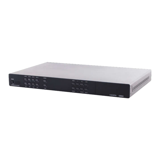
6. OPERATION CONTROLS AND FUNCTIONS 6.1 Front Panel POWER: Press this button to turn ON the device and the LED will be illuminated. IR WINDOW: This IR Receiver receives the IR signal from the IR Control provided with the CDPS-UC4H4HFS. OUT A~D: Press OUT button, then IN button to select an input source to an output display. -
Page 8: Rear Panel
6.2 Rear Panel IRL: Connect with IR Receiver, provided with the unit, for IR signal learning. Send the IR signal to be learnt direct towards the Receiver and use WebGUI to store the IR code. For details please refers to section 6.10.4 a) Note: Although both IR Extender and IR Learner may look the same, they are however different. - Page 9 Warning: The trigger event causes the execution of the Macro with the same number For example, the event on trigger N°1, if enabled, causes the execution of the Macro N°1 It’s possible to set by GUI the mode of the event (rise, falling, change).
-
Page 10: Remote Control
6.3 Remote Control 1 POWER: Press this button to switch the matrix ON/Stand-by 2 OUT A÷D: Press one button to select OUT; then press IN 1÷4 to select the input to be routed 3 IN 1÷4: Press one button to select the input to be routed to the output previously selected 4 ALL: Press this button to select all outputs... -
Page 11: Oled Menu
OLED Menu MAIN MENU SUB MENU DESCRIPTION DEFAULT EDID Mode All Input port use the same EDID. In menu “EDID All”, suitable EDID can be selected. Appoint Each Input port can match individual EDID. Menu “EDID IN1~4” selects suitable EDID. Exit... - Page 12 MAIN MENU SUB MENU DESCRIPTION DEFAULT 8/2D/ EDID All Sink A Copy Output A display EDID PCM/1080P Sink B Copy Output B display EDID Sink C Copy Output C display EDID Sink D Copy Output D display EDID 8/2D/PCM/720P Standard EDID. Content: deep color/2D3D/audio/ native resolution.
- Page 13 MAIN MENU SUB MENU DESCRIPTION DEFAULT Matrix Preset Preset 1 IN/OUT default A=1, B=2, C=3, No.1. Preset 2 IN/OUT default No.2. Preset 3 IN/OUT default No.3. Preset 4 IN/OUT default No.4. Exit HDCP Input IN1 Standard/ Set IN1 in Standard/ Standard Apple Apple mode.
- Page 14 MAIN MENU SUB MENU DESCRIPTION DEFAULT Source IN1 On/Off Detect IN1, IN2 Detection source with/without IN2 On/Off signal & HDCP. IN3 On/Off Detect IN3, IN4 source with/without IN4 On/Off signal & HDCP. Exit Sink A Info HPD On/Off Detect Sink A display with/without RSEN On/Off Hot-Plugging&...
-
Page 15: Ir Cable Pin Assignment
6.5 IR Cable Pin Assignment IR Blaster Power IR Signal IR Extender IR Signal Power Grounding Red dot IR Signal IR Learner Power Grounding Note: Due to both IR Extender and IR Learner cables are with similar outlook, a part no. "CBL-IR10C3SA200A sticker has been placed to differentiate the difference on IR Learner. -
Page 16: Rs-232 Protocol
6.6 RS-232 Protocol Use an RS232 with Sub-D 9 pin F/M straight cable MATRIX CONTROL DEVICE (Host) Assignment Assignment Baud Rate: 115200 bps Data bit: 8 bits Parity: None Flow Control: None Stop Bit: 1 6.7 RS-232 and Telnet Commands COMMAND DESCRIPTION PARAMETER... - Page 17 COMMAND DESCRIPTION PARAMETER RSTIP IP Configuration Set To NONE <DHCP> A N1 Select input N to output A N1=1~4 B N1 Select input N to output B N1=1~4 C N1 Select input N to output C N1=1~4 D N1 Select input N to output D N1=1~4 I N1 Select input N to all output...
- Page 18 COMMAND DESCRIPTION PARAMETER INNAME Show all Input name NONE INNAME N1 Show Input N1 name N1=1~4 INNAME N1 N2 Set Input N1 Name N1=1~4 N2=ABCDEFGH…(Max Length=8) OUTNAME Show all Output name NONE OUTNAME N1 Show Output N1 name N1=A~D OUTNAME N1 N2 Set Output N1 name N1=A~D N2=ABCDEFGH…(Max...
- Page 19 COMMAND DESCRIPTION PARAMETER COMSEND N1~N3 Send Desired data N1=COM, N2=Port 1/2, N3=Data String to Specified COM port Note: Some command may (See Note 4) require to add a carriage return (eg:\r or \x0D) in the end to allow the system to recognize it as an end of the command.
- Page 20 Note 2: This command is useful to send by RS232 an IR string to an external device by an IR emitter connected to one of the 8 IR port of the matrix CDPS-UC4H4HFS. In the GUI Control, go to the Command Settings section, open an IR command and copy the string to be transmitted.
- Page 21 Note 4: This command is useful to send a RS232 string to a peripheral device connected to port COM1 or COM2. As example, to send the simple command “1” followed by CR to the peripheral connected to COM1, the string to be sent is: COMSEND COM 1 1\x0D\x0D where: COMSEND COM...
- Page 22 b) To know the status and Mode of the trigger Input #1, send the string as it’s shown: TRIGGER N1 N2\x0D where: N1="Info"; N2=Port number.(1~8); \x0D is CR Sending command: trigger info 1 The matricx replies: Port 1:=Status=High, Active=Enable, Mode=Change (it means that the status of trigger #1 is high and that it’s enabled on change of the status) c) To set the mode of the trigger Input #1 as “Falling”, send the string as...
-
Page 23: Software Application
6.8 Software Application Please download the software from www.cypress.com.tw with file name CDPS V2.000 and save it in a directory where you may use it later. Alternatively download the software “Browser for LAN Modules” in the Available Software section of the page that show the CDPS-UC4H4HFS in the web site Elpro http://bit.ly/21PsvTv Connect the Control System with PC/Laptop through the Ethernet port... -
Page 24: Telnet Control
6.9 Telnet Control Under Mac iOS X, go to Go→Application→Utilities→Terminal. To access the telnet control under MS windows 7, click ‘Start’ menu and type “cmd” in the search field then press enter. To access the telnet control under Windows 10, click “All Applications”, then twice Windows PowerShell. - Page 25 Once the command line interface (CLI) appears, type "Telnet", then the IP address (in the case shown is 192.168.1.76), “23” and hit enter. (23 is the port number of CDPS-UC4H4HFS) This will bring into the unit which we wish to control. After the prompt >...
- Page 26 Note: Commands will not be executed unless followed by a carriage return. Commands are case-insensitive Warning: To operate by Telnet under the Windows systems, the functions “Client Telnet” and “Client TFTP” must be enabled.
-
Page 27: Webgui Control
6.10 WebGUI Control On a PC/Laptop that is connected to an active network system, open a web browser and type device’s IP address (available from OLED monitor) on the web address entry bar. A security page will appear to ask for User and Password, please key in “admin”... -
Page 28: Edid Settings
6.10.2 EDID Settings Click on 'EDID Settings' to select EDID Mode and Set EDID Input content for each HDMI input. 6.10.3 Macro Settings Macro 1~8 works aligned with Trigger IN 1~8. This means that when a trigger signal is activated, the control system will execute the Macro with the same number Click on 'Macro Settings' to execute the Macro. - Page 29 Click on Add button to insert commands. Then click on the command to be added Command must be setted depending on the destination: -SysCMD (internal the CDPS-UC4H4HFS, e.g. routing an Input to an Output) -Telnet (external devices, e.g. towards a CDPS-CS4) -COM (COM1 or COM2 of CDPS-UC4H4HFS) (IR1÷IR8 ports of CDPS-UC4H4HFS)
- Page 30 Port 23: See Note 1 in end of page Delay 100: See Note 2 in end of page Click on Save Change to confirm the settings. Note 1: When a command is intended to an external Telnet address, it’s necessary to set the Port Number as it follows: Port number for CDPS-CS4, CDPW-K1 and CDPW-K1S 7501 COM1 port number of CDPS-CS4...
-
Page 31: Command Creation And Settings
6.10.4 Command Creation and Settings The user can set up to 128 commands. The “standard” commands can have up to 128 characters. It’s possible to create “big” commands that have from 128 up to 512 characters. In this case, we can have 32 “big” commands and 96 “standard”... - Page 32 a1) On the other hand, there is a second way to store the IR code. You also can use the RS232 command "IRLEARN" to fetch the IR code; then you can copy the IR code shown on the console screen and paste it in the editing area Command (see above), and press "Save Change"...
- Page 33 c) How to create a command to close, open or toggle a relay After click on “Edit” a mask appears: Type the desired name of the command (in this case, “Close Relay") Type the parameter of command extracted from the RS232 parameters; in this case, “close”.
-
Page 34: Trigger Settings
6.10.5 Trigger Settings Click on “Trigger Settings” to view the current trigger status and edit the trigger behavior. Default setting Status is on Low, Active is on Enable and Mode is on Change, where Status represents current input connection signal status; Active represents enabling or not the trigger action and Mode represents the trigger setting of the input signal. -
Page 35: Network Settings
6.10.7 Network Settings Click on 'Network Settings' to set the device’s IP Mode. Once the change is saved the system will reset the IP address on the device automatically and user will need to re-enter the IP address to continue the WebGUI function. 6.10.8 System Settings Click on 'System Settings' to set power to On/Standby. -
Page 36: Connection Diagram
7. CONNECTION DIAGRAM Integrated 3rd Party Control RS-232 Alarm Blind Screen Lighting Sensor Control Control Control RS-232 IR Blasters 1.5m IR Learner 60° 60° INF RAR ED O UT COM 1 COM 2 OU T HDMI IN HDM I OU T SER VIC E CO NTR OL IR BLASTER... - Page 37 RS-232 Controlled Smart TV Device Games Console RS-232 Controlled Device PC/Laptop Media Sever LAN Connections DC 5V Power Supply RS2 32 IR IN IR Extender RS-232 RS-232 Equipped PC/Laptop Internet Connected Router HDMI Outputs Smart TV Smart TV Smart TV...
-
Page 38: Specifications
8. Specifications 8 .1 Technical Specifications Video Bandwidth 300 MHz/3 Gbps Input Ports 4×HDMI, 1×IR Learning, 8×Triggers (Terminal Block), 2×COM (9-pin D-sub), 4×LAN (RJ- 45), 1×IP Control (RJ-45), 1×RS-232 (9-pin D-sub), 1×IR (Remote Only), 1×USB (Service Only) Output Ports 4×HDMI, 8×IR, 8×Relays (Terminal Block) HDMI Cable Length 10M/1080p, 5M/4K2K Resolutions Support... -
Page 39: Supported Resolutions
8.2 Supported Resolutions RESOLUTIONS INPUT OUTPUT 640×480@60/72/75/85 √ √ 720×400@85 √ √ 800×600@560/60/72/75/85 √ √ 1024×768@60/70/75/85 √ √ 1152×864@75 √ √ 1280×720@60 √ √ 1280×768@60/75/85 √ √ 1280×800@60 (RB) √ √ 1280×800@60 √ √ 1280×960@60 √ √ 1280×1024@60 √ √ 1360×768@60 √... -
Page 40: Acronyms
RESOLUTIONS INPUT OUTPUT 1920×1080i@50/60 √ √ 1920×1080p@24/25/30/50/60 √ √ 3840×2160p@24/25/30 √ √ 3840×2160p@50/60 (YUV420) √ √ 4096×2160p@24/25/30 √ √ 4096×2160p@50/60 (YUV420) √ √ 9. ACRONYMS ACRONYM COMPLETE TERM Command Line Interface Digital Visual Interface Graphical User Interface HDCP High-bandwidth Digital Content Protection HDMI High-Definition Multimedia Interface HDTV...
Need help?
Do you have a question about the Elpro Video Labs CDPS-UC4H4HFS and is the answer not in the manual?
Questions and answers