Table of Contents
Advertisement
Sep.2004
TABLE DF CONTENTS
CAUTIONARY NOTES ...................................................2
SPECIFICATIONS.............................................................2
LOCATION OF CONTROLS ..........................................4
LOCATION OF CONTROLS PARTS LIST ...................5
EXPLODED VIEW, EXPLODED
VIEW PARTS LIST ........................6
PARTS LIST......................................................................10
CHECKING THE VERSION NUMBER.......................13
SERIAL DUMP (SYSTEM UPDATE, USERS
DATA SAVE AND LOAD) ..............13
INSTRUCTIONS FOR FACTORY RESET ...................14
Copyright © 2004 ROLAND CORPORATION
All rights reserved. No part of this publication may be reproduced in any form without the written permission
of ROLAND CORPORATION.
TEST MODE.....................................................................14
BLOCK DIAGRAM.........................................................19
CIRCUIT BOARD (PANEL) ..........................................20
CIRCUIT DIAGRAM (PANEL).....................................22
CIRCUIT BOARD (JACK)..............................................24
CIRCUIT DIAGRAM (JACK 1) .....................................26
CIRCUIT DIAGRAM (JACK 2) .....................................28
17058256E0
SERVICE NOTES
Issued by RJA
Printed in Japan (0500) (TP)
RC-20XL
Advertisement
Table of Contents

Related Manuals for Roland Boss RC-20XL


Summary of Contents for Roland Boss RC-20XL
-
Page 1: Table Of Contents
SERIAL DUMP (SYSTEM UPDATE, USERS DATA SAVE AND LOAD) ....13 INSTRUCTIONS FOR FACTORY RESET ....14 Copyright © 2004 ROLAND CORPORATION All rights reserved. No part of this publication may be reproduced in any form without the written permission of ROLAND CORPORATION. -
Page 2: Cautionary Notes
Sep.2004 CAUTIONARY NOTES AUX IN Jack (Stereo miniature phone type) PHRASE SHIFT Jack (1/4 inch TRS phone type) REVERSE Jack (1/4 inch phone type) OUTPUT Jack (1/4 inch phone type) User data status AC Adaptor Jack Power User data status after each of the following processes is described below. Whenever carrying out procedures that involve deleting or erasing user data, DC 9V: Dry battery (R6/LR6 (AA) type) x 6 always be sure to back up the user data to some form of external media (refer... - Page 3 RC-20XL...
-
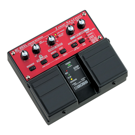
Page 4: Location Of Controls
Sep.2004 LOCATION OF CONTROLS fig.panel... -
Page 5: Location Of Controls Parts List
RC-20XL LOCATION OF CONTROLS PARTS LIST PART CODE CATEGORY PART NAME DESCRIPTION Q’TY G2017145 CASING TOP CASE G2187530 CASING PEDAL R G2187531 CASING PEDAL L G2357116 CASING PEDAL PLATE 62X53 H5029851 CASING PEDAL SHAFT G2217185 CASING PANEL H5029855 SCREWS SCREW M4X8 HEXAGON BUTTON HEAD NI F3279802 POTENTIOMETER... -
Page 6: Exploded View, Exploded View Parts List
Sep.2004 EXPLODED VIEW, EXPLODED VIEW PARTS LIST EXPLODED VIEW1 fig.explo-1 RIGHT SIDE LEFT SIDE EXPLODED VIEW 1 PARTS LIST [PART] PART CODE PART NAME DESCRIPTION Q’TY G2017145 TOP CASE G2357111 CUSHION R H5029851 PEDAL SHAFT 2215770201 PEDAL GUIDE BUSH 215-702 2217710900 COIL SPRING 217-109... - Page 7 RC-20XL EXPLODED VIEW 2 fig.explo-2 EXPLODED VIEW 2 PARTS LIST [PART] PART CODE PART NAME DESCRIPTION Q’TY G2477122 R-KNOB G2217185 PANEL G2217186 LED PANEL G247751301 VGA KEYTOP S WITHOUT LENS G247751001 VGA KEYTOP S BLACK WITH LENS [SCREW] PART CODE PART NAME DESCRIPTION Q’TY...
- Page 8 Sep.2004 EXPLODED VIEW 3 fig.explo-3 Refer to Fig A Magnified view Magnified view EXPLODED VIEW 3 PARTS LIST [PART] PART CODE PART NAME DESCRIPTION Q’TY G2017148 BOTTOM COVER G2357118 BOTTOM FOOT G2017621 BATTERY COVER G2017620 BATTERY CASE G2177308 BATTERY TERMINAL(+) G2177309 BATTERY TERMINAL(-) G2177307...
- Page 9 RC-20XL EXPLODED VIEW (Fig. A) fig.explo-4 EXPLODED VIEW(Fig. A) PARTS LIST [PART] PART CODE PART NAME DESCRIPTION Q’TY G2017145 TOP CASE 75E183M000 JACK BOARD ASSY 75E183P000 PANEL BOARD ASSY G225712901 INSULATING SHEET CENTER G2527110 REAR PANEL ******** This PWB ASSY is inclueded the JACK BOARD ASSY. G2147821 JACK HOLDER [SCREW]...
-
Page 10: Parts List
Sep.2004 PARTS LIST fig.part1e Due to one or more of the following reasons, SAFETY PRECAUTIONS: parts with parts code ******** cannot be supplied as service parts. The parts marked have safety-related characteristics. Use • Part supplied only as a component in a complete assembly only listed parts for replacement. - Page 11 RC-20XL DIODE F5019309 02DZ5.1-Y ZENNER DIODE D9 on PB F5029126 L-113GDT POWER LED LED17 on PB F5029125 L-34YDSL LED (YELLOW) LED6 on PB 1502928100 L-34HDSL LED (RED) LED2,LED3,LED4,LED12,LED13,LED14,LE D15,LED16 F5029124 L-34GDSY LED (GREEN) LED5,LED7 on PB 15029342 GL3ED8 LED1 on PB F5029117 L-312LRD LED8,LED9,LED10,LED11 on PB...
- Page 12 Sep.2004 INDUCTOR,COIL,FILTER F5409117 NFM4516P13C204F EMI FILTER C80 on JK 12449386 SBT-0180W EMI FILTER FL1 on JK F2449209 SLF7032T-151MR29-2(150UH) COIL L20 on JK CRYSTAL,RESONATOR F5299114 HC-49SM 5MHZ CRYSTAL X3 on JK F5299104 MA-406 (24.576MHZ) CRYSTAL X2 on JK CONNECTOR F3439160 53015-0210 2P P=2MM CONNECTOR CN6 on JK F3439167...
-
Page 13: Checking The Version Number
RC-20XL CHECKING THE VERSION Connect the REVERSE jack and PHRASE SHIFT jack respectively. Transmitting RC-20XLReceiving RC-20XL NUMBER REVERSE ----------> PHRASE SHIFT PHRASE SHIFT ----------> REVERSE Completely turn down all volume controls. Start up the transmitting RC-20XL in Dump mode. 1) While holding down the [TAP TEMPO] and [AUTO START] buttons,turn Hold down the left pedal (ON/OFF) and right pedal (TAPL/MEMORY) on the power of the transmitting RC-20XL. -
Page 14: Instructions For Factory Reset
Sep.2004 INSTRUCTIONS FOR FACTORY RESET 16. PHRASE SELECT volume check 17. Noise check 18. Battery operation check The RC-20XL can be restored to its original factory settings with the following procedure. Items required for tests • Oscillators x 2 Restoring the factory settings with this procedure requires another RC-20XL •... - Page 15 RC-20XL Exiting Test Mode • Press the AUTO START switch, and verify that “AUTO START” goes dark. Turn off the power • Press the MODE switch, and verify that “INST & MIC”, “NORMAL”, “CENTER CANCEL”, and “FLAT AMP SIMULATE” go dark. Explanation of each test item •...
- Page 16 Sep.2004 6.DA check fig.INST_40 • Once again check the output wavwform at the point that “5.GUIDE volume check” is completed, to check the DC leakage and level.In the following cases, the result is NG. Excessive level NG Insufficient level NG ↑...
- Page 17 RC-20XL 11.AUX IN (NORMAL) check (0.5V/DIV, 1mS/DIV) 1.8Vp-p 0.2Vp-p • Set the PHRASE SELECT volume to the ‘6’ position. • Verify that “LOOP QUANTIZE” is dark and “LOOP PHRASE” is lit. 15.solder spot check • Verify that the output waveform is the same as the waveform shown in •...
- Page 18 Sep.2004 Always check the battery after repairing or servicing the product. Skipping directly to the desired test • Enter Test mode. • The FLASH ROM check will occur automatically, and if there is no problem, all LEDs other than “PEAK” will light. •...
-
Page 19: Block Diagram
RC-20XL BLOCK DIAGRAM fig.block.eps... -
Page 20: Circuit Board (Panel)
Sep.2004 CIRCUIT BOARD (PANEL) fig.b-panel-1 View from components side fig.b-panel-2 View from foil side... - Page 21 RC-20XL...
-
Page 22: Circuit Diagram (Panel)
Sep.2004 RC-20XL CIRCUIT DIAGRAM (PANEL) SKQKAB MODE SKQKAH 1SS352 PEDAL_R SKQKAB 1SS352 EXIT SKQKAB 1SS352 AUTO START SKQKAB 1SS352 (green) L-34GDSL L-34YDSL LED1 L-34GDSL SKQKAB TEMPO LED5 LED6 GL3ED8 LED7 LOOP 1SS352 OVER WRITE PHRASE PLAY SKQKAH 1SS352 TEMPO L-34HDSL L-34HDSL L-34HDSL LED2... -
Page 23: Circuit Board(Jack)
Sep.2004 CIRCUIT BOARD(JACK) View from components side View from foil side... - Page 24 RC-20XL...
-
Page 25: Circuit Diagram (Jack1)
Sep.2004 RC-20XL CIRCUIT DIAGRAM (JACK1) AVcc VR_VDD N.I.U FROM DIGITAL BLOCK AVcc AVcc INST IN PEAK_LED MIC IN POWER_LED 0.47/16S MIC_IN MIC_OUT INST 2SK880GR MIC OUT N.I.U N1608Z601T01 AVcc INST_OUT HTJ-064-12I 1_2VCC INST_IN 1SS302 AVcc AVcc N.I.U A2001WR2-14P IC8E TC4066BFT 2SK880GR 1SS355 TO CN2 ON... -
Page 26: Circuit Diagram (Jack 2)
Sep.2004 RC-20XL CIRCUIT DIAGRAM (JACK 2) fig.c-digital P103 INST_MUTE P103 FLAT_AMP_ON/OFF P104 P104 P105 MIC_MUTE P105 AUX_NORM_MUTE P106 P106 P107 AUX_C.CANCEL_MUTE P107 TP10 TP11 TP12 TP13 TP14 TP15 TP16 D 3. 3 (SERIAL_IO1) T-SHIFT T-SHIFT T-SHIFT2 T-SHIFT2 (SERIAL_IO2) REVERSE REVERSE FET_SW FET_SW N1608Z601T01... - Page 27 Sep.2004...
Need help?
Do you have a question about the Boss RC-20XL and is the answer not in the manual?
Questions and answers