Table of Contents
Advertisement
Advertisement
Table of Contents

Subscribe to Our Youtube Channel
Related Manuals for Telycam TLC-1000-U3-10


Summary of Contents for Telycam TLC-1000-U3-10
- Page 1 USB3.0 HD Video Camera User Manual Version V1.0 (English)...
-
Page 3: Table Of Contents
CONTENTS SAFE GUIDES.…………………...…………………………………..…..…........…3 ACCESSORIES……………………………………………………………………..…........3 QUICK START..............................4 PRODUCT HIGHLIGHTS............................5 PRODUCT SPEC..............................5 CAMERA INTERFACE............................6 CAMERA DIMENSION............................6 IR REMOTE CONTROLLER..........................7 LEARNING FUNCTION.............................8 VISCA IN(RS232) PORT.............................9 VISCA PROTPCOL............................10 PELCO-D PROTOCOL............................16 PELCO-P PROTOCOL............................17 OSD MENU..............................18 UVC CONTROL..............................21... -
Page 4: Safe Guides
SAFETY GUIDES 1.Before operation, please fully read and follow all instructions in the manual. For your safety, always keep this manual with the camera. 2.The camera power input range is 100-240VAC(50-60Hz),ensure the power supply input within this rate before powering on. 3.The camera power voltage is 12VDC, rated currency is 1.5A. -
Page 5: Quick Start
QUICK START Check all cable connections before power on. 2. DIP Switch Setting (at the bottom of the camera): Function(ARM) SW-1 SW-2 Instruction Updating mode Debugging mode Undefined Working mode Function (IR CODE TYPE) SW-3 SW-4 Instruction Off(Close IR receiver) Undefined SEJIN 4PPM CODE NEC CODE(standard) -
Page 6: Product Highlights
PRODUCT HIGHLIGHTS Smart and fashion design, ideal for cloud-based conferencing Adopts advanced DSP,1/2.8 inch 5MP image sensor, and high quality 10X 62.5degree FOV optical lens, provides fluent and crystal image quality Fast switching between different video formats: less than 1 second ... -
Page 7: Camera Interface
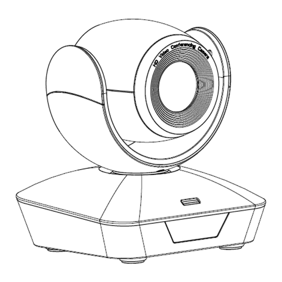
CAMERA INTERFACE 1.Camera Lens 5.Dial Switch 9.USB3.0 Port 2.Camera Base 6. Tripod Screw Hole 10.12VDC Power Input 3.IR Receiver Panel 7.Installation Hole 11.Power Indicator light(red) 4.Indicator Light 8.RS232(VISCA IN) Port CAMERA DIMENSION(MM) -
Page 8: Ir Remote Controller
IR REMOTE CONTROLLER LED Function Instruction Press any button and shows in red color: Current selection is to control the camera; Press any button and shows in green color: Current selection is to control the codec; Press any button and shows in blue color: Current selection is to control the TV; Power button Red button: in normal work mode, short press one time, camera will enter standby mode;... -
Page 9: Learning Function
LEARNING FUNCTION: Press the green button, the LED indicator light will show in green color for 1 second, means switch to video terminal/codec control mode; 2.Single Button Coding: long press(3seconds) Home +number"1" button simultaneously, the green indicator LED will light, enter button learning mode, press the buttons which need to be learned, LED will start flickering(1HZ), now can start button learning: get the codec remote point to the camera remote’s infrared tube( about 10cm distance), then press the button which need to be learned, the LED re-flickering when learning finishes ;... -
Page 10: Visca In(Rs232) Port
VISCA IN (RS232) PORT Function IR OUT VISCA IN &RS485 Connection VISCA IN &DB9 Connection Camera VISCA IN RS485 Camera VISCA IN Windows DB-9 A(+) A(+) A(+) IR OUT IR OUT B(-) B(-) B(-) SERIAL PORT CONFIGURATION: Parameter Value Parameter Value Baud rate 2400/4800/9600/115200... -
Page 11: Visca Protpcol
VISCA PROTOCOL Part1 Camera Return Command Ack/Completion Message Command Packet Note z0 41 FF Returned when the command is accepted. Completion z0 51 FF Returned when the command has been executed. z = camera adderss+8 Error Messages Command Packet Note Returned when the command format is different or when a Syntax Error z0 60 02 FF... - Page 12 Command Function Command Packet Note OnePush 8x 01 04 35 03 FF 8x 01 04 35 04FF Manual 8x 01 04 35 05 FF Sodium Lamp 8x 01 04 35 08 FF Fluorescent lamp 8x 01 04 35 09 FF Reset 8x 01 04 03 00 FF 8x 01 04 03 02 FF...
- Page 13 Command Function Command Packet Note 8x 01 04 3D 02 FF WDR ON/OFF CAM_WDR 8x 01 04 3D 03 FF Direct 8x 01 04 D3 0p FF pq: WDR Position (1~0x06) 8x 01 04 33 02 FF BackLight On CAM_BackLight 8x 01 04 33 03 FF BackLight Off Reset...
- Page 14 Command Function Command Packet Note 8x 01 06 01 VV WW 03 01 FF Down 8x 01 06 01 VV WW 03 02 FF Left 8x 01 06 01 VV WW 01 03 FF Right 8x 01 06 01 VV WW 02 03 FF Upleft 8x 01 06 01 VV WW 01 01 FF VV: Pan speed 0x01 (low speed) to...
- Page 15 CAM_IrisPosInq 8x 09 04 4B FF y0 50 00 00 0p 0q FF pq: Iris Position CAM_GainPosiInq 8x 09 04 4C FF y0 50 00 00 0p 0q FF pq: Gain Position CAM_ BrightPosiInq 8x 09 04 4D FF y0 50 00 00 0p 0q FF pq: Bright Position y0 50 02 FF CAM_ExpCompModeInq...
- Page 16 60/30mode 50/25mode 1/10000 close 1/10000 1/6000 1/6000 1/4000 1/3500 1/3000 F9.6 1/2500 1/2000 1/1750 F6.8 1/1500 1/1250 F5.6 1/1000 1/1000 1/725 F4.8 1/600 1/500 Iris 1/425 1/350 F3.4 1/300 Shutter 1/250 F2.8 1/215 speed F2.4 1/180 1/150 1/125 1/120 1/100 F1.6 1/100 1/90...
-
Page 17: Pelco-D Protocol
PELCO-D PROTOCOL Function Byte1 Byte2 Byte3 Byte4 Byte5 Byte6 Byte7 0xFF Address 0x00 0x08 Pan Speed Tilt Speed Down 0xFF Address 0x00 0x10 Pan Speed Tilt Speed Left 0xFF Address 0x00 0x04 Pan Speed Tilt Speed Right 0xFF Address 0x00 0x02 Pan Speed Tilt Speed... -
Page 18: Pelco-P Protocol
PELCO-P PROTOCOL Function Byte1 Byte2 Byte3 Byte4 Byte5 Byte6 Byte7 Byte8 0xA0 Address 0x00 0x08 Pan Speed Tilt Speed 0xAF Down 0xA0 Address 0x00 0x10 Pan Speed Tilt Speed 0xAF Left 0xA0 Address 0x00 0x04 Pan Speed Tilt Speed 0xAF Right 0xA0 Address... -
Page 19: Osd Menu
OSD MENU 1.under working mode, press the menu button on the IR remote, to enter the OSD menu ; 2.Use the navigate button to select the main menu. Once been selected, the main menu will change to grey color background, and the right side will show all parameters under this sub menu : 3.Press the right navigate button to enter sub menu, use up and down navigate button to select parameter;... - Page 20 FOCUS LIMIT The target distance: 1.5M/2M/3M/6M/10M 1.5M D_ZOOM Digital Zoom: OFF/ON ZOOM SPEED Set zoom speed level:0~7 LENS INIT Lens focus parameter frequency setting, choose EXE to start the lens focus reset DIS ZOOM RATIO Display zoom value during zooming control RETURN Return to previous menu WB MODE...
- Page 21 2D NR ON/OFF 3D NR OFF/AUTO/1~4 AUTO D_WDR Set dynamic level : OFF/1~6 IMAGE GAMMA Set gamma: 0~4 ENHANCE BACKLIGHT ON/OFF HIGHLIGHT ON/OFF RETURN Return to previous menu MASK SWITCH Privacy zone function: ON/OFF Set mask zone color: WHITE COLOUR WHITE/YELLOW/GRAY/GREEN/VIOLET/RED INDEX Set mask zone number: 1~8...
-
Page 22: Uvc Control
CONTROL DATE Control firmware release date: YY/MM/DD BAUDRATE Current baud rate value PARITY BIT Current control protocol parity bit value RETURN Return to previous menu RESET REEST to defaulted value (except the Language): ON/OFF UVC CONTROL 1. Only run the client software after the USB3.0 camera has completed self-configuration(the IR indicator in blue color and will not flash);...
Need help?
Do you have a question about the TLC-1000-U3-10 and is the answer not in the manual?
Questions and answers