Table of Contents
Advertisement
Quick Links
USER MANUAL
PXIe-1086DC
PXIe, 18-Slot (16 Hybrid Slots, 1 PXI Express Slot), Up to 12 GB/s
PXI Chassis
The manual includes instructions for installing and configuring your PXIe-1086DC chassis
and PXI Express system.
Contents
Getting Started.......................................................................................................................... 2
Unpacking......................................................................................................................... 2
What You Need to Get Started..........................................................................................2
Key Features..................................................................................................................... 2
Chassis Description...........................................................................................................3
Optional Equipment.......................................................................................................... 5
PXIe-1086DC Chassis Backplane Overview....................................................................6
Installation and Configuration................................................................................................ 12
Safety Information.......................................................................................................... 12
Chassis Cooling Considerations......................................................................................13
Fan Access Door Clearance............................................................................................ 16
Rack Mounting................................................................................................................16
Connecting to Safety Ground and Power Source............................................................16
Power-On Test.................................................................................................................18
Installing a PXI Express System Controller................................................................... 18
Installing Peripheral Modules......................................................................................... 20
Remote System Monitoring............................................................................................ 21
LED Indicators................................................................................................................ 22
Remote Inhibit and Fault Monitoring............................................................................. 24
Inhibit Mode Switch........................................................................................................24
PXI_CLK10 Front Panel Connectors............................................................................. 25
PXI Express System Configuration with MAX.............................................................. 25
Using System Configuration and Initialization Files...................................................... 27
Maintenance............................................................................................................................ 28
Service Interval............................................................................................................... 28
Preparation...................................................................................................................... 28
Advertisement
Table of Contents

Subscribe to Our Youtube Channel
Related Manuals for National Instruments PXIe-1086DC


Summary of Contents for National Instruments PXIe-1086DC
-
Page 1: Table Of Contents
USER MANUAL PXIe-1086DC PXIe, 18-Slot (16 Hybrid Slots, 1 PXI Express Slot), Up to 12 GB/s PXI Chassis The manual includes instructions for installing and configuring your PXIe-1086DC chassis and PXI Express system. Contents Getting Started.......................... 2 Unpacking......................... 2 What You Need to Get Started..................2 Key Features........................ -
Page 2: Getting Started
Ferrite bead for use with redundant power supplies Key Features The PXIe-1086DC chassis combines a high-performance 18-slot PXI Express backplane with a high-output power supply and a structural design that has been optimized for maximum 2 | ni.com | PXIe-1086DC User Manual and Specifications... -
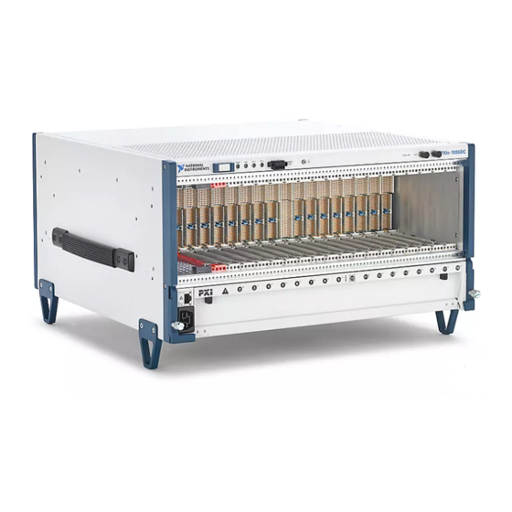
Page 3: Chassis Description
Slot blockers for improved cooling performance • Factory installation services • Replacement fan modules Chassis Description The following figures show key features of the PXIe-1086DC chassis front and back panels. PXIe-1086DC User Manual and Specifications | © National Instruments | 3... - Page 4 5. Backplane Connectors 14. Chassis Power Connector 6. Clk10 Output 15. Ethernet Port 7. Clk10 Input 16. Chassis Carry Handle 8. PXI Filler Panels (Optional) 17. System Controller Expansion Slots 9. Removable Feet 4 | ni.com | PXIe-1086DC User Manual and Specifications...
-
Page 5: Optional Equipment
PXIe-1086DC chassis with a single power supply. Rack Mount Kits There are two optional kits for mounting the PXIe-1086DC chassis into a rack. The first option is a pair of mounting brackets for use on the front of the chassis. The second option is a rear rack mount kit. -
Page 6: Pxie-1086Dc Chassis Backplane Overview
Replacement fan modules are available from National Instruments. PXIe-1086DC Chassis Backplane Overview Interoperability with CompactPCI The design of the PXIe-1086DC provides you the flexibility to use the following devices in a single PXI Express chassis: • PXI Express compatible products •... - Page 7 Port 16 Port 17 Port 8 Port 9 PCIe-to- PCIe-to- PCI Bus (32-bit, 33 MHz) to slots 2-9 PCI Bus (32-bit, 33 MHz) to slots 11-18 Bridge #2 Bridge #1 PXIe-1086DC User Manual and Specifications | © National Instruments | 7...
- Page 8 STAR 13 DSTAR 4 DSTAR 16 STAR 5 STAR 14 DSTAR 7 DSTAR 13 STAR 6 STAR 15 DSTAR 5 DSTAR 14 STAR 7 STAR 16 DSTAR 6 DSTAR 15 STAR 8 8 | ni.com | PXIe-1086DC User Manual and Specifications...
- Page 9 1 ns between slots) drives PXI_CLK10 to each peripheral slot. You can use this common reference clock signal to synchronize multiple modules in a measurement or control system. PXIe-1086DC User Manual and Specifications | © National Instruments | 9...
- Page 10 10 MHz REF IN connector on the front of the chassis, the signal on the System Timing Slot is selected. Refer to the following table which explains how the 10 MHz clocks are selected by the backplane. 10 | ni.com | PXIe-1086DC User Manual and Specifications...
- Page 11 PXIe_SYNC100 signal. On the next PXI_CLK10 edge the PXIe_SYNC100 signal restarts. This allows several chassis to have their PXIe_SYNC100 in phase with each other. Refer to the following figure for timing details with this method. PXIe-1086DC User Manual and Specifications | © National Instruments | 11...
-
Page 12: Installation And Configuration
• Part Replacement—Only service this equipment with parts that are exact replacements, both electrically and mechanically. Contact National Instruments for replacement part information. Installation of parts with those that are not direct replacements may cause harm to personnel operating the chassis. Furthermore, damage or fire may occur if replacement parts are unsuitable. -
Page 13: Chassis Cooling Considerations
Chassis Cooling Considerations The PXIe-1086DC chassis is designed to operate on a bench or in an instrument rack. The chassis must be oriented horizontally with the primary exhaust vent at top. Vertical orientation with the chassis handle up is not a supported configuration. - Page 14 Figure 8. PXIe-1086DC Cooling Clearances Dimensions are in inches (millimeters) 1.75 (44.5) PXIe-1086DC 1.75 (44.5) 3.00 (76.2) The vent locations are shown in the following figure. 14 | ni.com | PXIe-1086DC User Manual and Specifications...
- Page 15 Select High for maximum cooling performance or Auto for improved acoustic performance. When set to Auto, the chassis intake air temperature determines the fan speed. PXIe-1086DC User Manual and Specifications | © National Instruments | 15...
-
Page 16: Fan Access Door Clearance
Fan Access Door Clearance When installing the PXIe-1086DC chassis, you also must provide the proper clearance for the fan access door to open fully, as shown in the following figure. Figure 10. Fan Access Door Clearance Dimensions are in inches (millimeters) 0.35... - Page 17 The PXIe-1086DC ships with a power cord that has an appliance coupler and leads for connection to the source. The cord requires custom termination. The following figure shows the cord connector pinout. You can order an additional or replacement cord from National Instruments. Part number 782108-01 is a US/CAN approved 3 m, three-conductor, 18 AWG cord with leads and suitable for use in North America.
-
Page 18: Power-On Test
To completely remove power, you must disconnect all power cables. The PXIe-1086DC chassis has two slots for inserting power supplies on the rear of the chassis. A power supply must be installed in one or both of these slots to power on the chassis. - Page 19 The following figure shows a PXI Express system controller installed in the system controller slot of a PXIe-1086DC chassis. You can place CompactPCI, CompactPCI Express, PXI, or PXI Express modules in other slots depending on the slot type.
-
Page 20: Installing Peripheral Modules
Getting Started section for a description of the various slot types. This section contains general installation instructions for installing a peripheral module in a PXIe-1086DC chassis. Refer to your peripheral module user manual for specific instructions and warnings. To install a module, complete the following steps: Ensure that the chassis is properly grounded to protect it from electrical damage while you install the module. -
Page 21: Remote System Monitoring
(2x) Remote System Monitoring The PXIe-1086DC chassis provides an Ethernet port on the front panel of the chassis. You can use this Ethernet port to monitor the chassis operating parameters remotely over a network. The Ethernet port on the chassis supports communication speeds of 10 Mbps and 100 Mbps. -
Page 22: Led Indicators
• Default hostname as printed on the product label LED Indicators The PXIe-1086DC chassis has four main LEDs on the front panel next to the Power Inhibit switch. Refer to Front View of the PXIe-1086DC to locate these LEDs. You can use the four main LEDs to determine the chassis operating status quickly. - Page 23 Power supply is active, and at least one voltage is out Blinking red of range. Steady red Power supply has failed. Each chassis fan assembly has an LED that shows the current health of that fan. PXIe-1086DC User Manual and Specifications | © National Instruments | 23...
-
Page 24: Remote Inhibit And Fault Monitoring
Power supply is operating normally. Steady red Power supply has failed. Remote Inhibit and Fault Monitoring The PXIe-1086DC chassis supports remote inhibit and fault monitoring through a 4-pin terminal block on the chassis front panel. Refer to Front View of the PXIe-1086DC to locate this connector. -
Page 25: Pxi_Clk10 Front Panel Connectors
Inhibit Mode switch must be in the Manual position. PXI_CLK10 Front Panel Connectors There are two SMA connectors on the front of the PXIe-1086DC chassis for PXI_CLK10. The connectors are labeled IN and OUT. You can use them for supplying the backplane with PXI_CLK10 or routing the backplane’s PXI_CLK10 to another chassis. - Page 26 Static reservation pre-allocates a trigger line to prevent its configuration by a user program. Dynamic reservation/routing/deallocation is on the fly within a user program based on National Instruments APIs such as NI-DAQmx. NI recommends dynamic reservations and routing are used whenever possible. If static reservations are required, static reservation of trigger lines can be implemented by the user in MAX through the Triggers tab.
-
Page 27: Using System Configuration And Initialization Files
PXI Trigger Bus Routing Some National Instruments chassis, such as the PXIe-1086DC, have the capability to route triggers from one bus to others within the same chassis using the Trigger Routing tab in MAX. Note Selecting any non-disabled routing automatically reserves the line in all trigger buses being routed to. -
Page 28: Maintenance
For detailed information regarding initialization files, refer to the PXI Express specification at www.pxisa.org Maintenance This section describes basic maintenance procedures you can perform on the PXIe-1086DC chassis. Caution Disconnect the power cable prior to servicing your PXIe-1086DC chassis. -
Page 29: Replacing A Modular Power Supply
Removal of Power Supply The PXIe-1086DC power supply (part number 782106-01) is a replacement part for the PXIe-1086DC chassis. Before attempting to replace a power supply, verify that there is adequate clearance behind the chassis. - Page 30 Disengage the two screws on the rear of the power supply with a flat-blade screwdriver. Extend the collapsible handle and pull the power supply out of the chassis. Figure 18. Removing Power Supply from the PXIe-1086DC Chassis 1. Power Supply 2.
- Page 31 4. Power Supply Caution If you are using the PXIe-1086DC and SC Express modules with front mounting terminal blocks together, you must remove the SC Express module front mount terminal blocks to access the power drawer. Refer to your module documentation for more information about removing the terminal blocks.
- Page 32 PXIe-1086DC Power Drawer. Caution If you are using the PXIe-1086DC and SC Express modules with front mounting terminal blocks together, you must remove the SC Express module front mount terminal blocks to access the power drawer. Refer to your module documentation for more information about removing the terminal blocks.
-
Page 33: Replacing A Modular Fan Assembly
If all fans are installed and operating normally, you can remove any fan without causing the system to shut down. The following figure shows the PXIe-1086DC chassis with a fan assembly removed. PXIe-1086DC User Manual and Specifications | © National Instruments | 33... - Page 34 Open the fan door by sliding the door latches inward and rotating the door down. Slide the fan module into an empty fan slot with the connector facing the chassis until it latches. 34 | ni.com | PXIe-1086DC User Manual and Specifications...
-
Page 35: Specifications
Maximum Current Single Power Maximum Current Dual Power Voltage Supply Supplies +3.3 V 50 A 60 A +5 V 40 A 49 A The operating range is guaranteed by design. PXIe-1086DC User Manual and Specifications | © National Instruments | 35... - Page 36 +5 V. Note The maximum power dissipated in the system slot should not exceed 140 W. Note The maximum power dissipated in a peripheral slot should not exceed 38.25 W. 36 | ni.com | PXIe-1086DC User Manual and Specifications...
- Page 37 Module cooling exhaust Along top of chassis Power supply cooling system Forced air circulation through integrated fan Power supply cooling intake Rear of chassis Power supply cooling exhaust Top of chassis PXIe-1086DC User Manual and Specifications | © National Instruments | 37...
-
Page 38: Environmental
(NI part number 784057-01) in the empty slot to meet operational shock and vibration specifications. Acoustic Emissions Sound Pressure Level (at Operator Position) Auto fan (up to ~30 °C ambient) 57.0 dBA High fan 69.0 dBA 38 | ni.com | PXIe-1086DC User Manual and Specifications... -
Page 39: Backplane
Auto fan (up to ~30 °C ambient) 63.3 dBA High fan 79.3 dBA Caution The protection provided by the PXIe-1086DC can be impaired if it is used in a manner not described in this document. Backplane Size 3U-sized; one system slot (with three system expansion slots) and 17 peripheral slots. - Page 40 Maximum slot-to-slot skew 250 ps Backplane characteristic impedance 65 Ω ±10% For PXI slot to PXI Star mapping, refer to System Timing Slot. For other specifications, refer to the PXI-1 Hardware Specification. 40 | ni.com | PXIe-1086DC User Manual and Specifications...
-
Page 41: Mechanical
Electroplated Nickel on Cold Rolled Steel, Polyurethane Enamel The following figures show the PXIe-1086DC chassis dimensions. The holes shown are for the installation of the optional rack mount kits. You can install those kits on the front or rear of the chassis, depending on which end of the chassis you want to face toward the front of the instrument cabinet. - Page 42 (221.9) 1.84 (46.8) 14.35 (364.40) 1.23 1.82 1.82 2.09 (31.3) (46.3) (46.3) (53.2) 10.70 (271.8) 1.84 3.54 (46.8) (90.0) 5.57 (141.5) 0.84 10.10 0.75 (21.3) (256.1) (19.1) 2.13 (54.2) 17.80 (452.7) 42 | ni.com | PXIe-1086DC User Manual and Specifications...
- Page 43 Figure 22. PXIe-1086DC Chassis Dimensions (Bottom) Dimensions are in inches (millimeters) 0.18 (4.7) PXIe-1086DC User Manual and Specifications | © National Instruments | 43...
- Page 44 • EN 61326-1 (IEC 61326-1): Class A emissions; Basic immunity • EN 55011 (CISPR 11): Group 1, Class A emissions • AS/NZS CISPR 11: Group 1, Class A emissions 44 | ni.com | PXIe-1086DC User Manual and Specifications...
- Page 45 At the end of the product life cycle, all NI products must be disposed of according to local laws and regulations. For more information about how to recycle NI products in your region, visit ni.com/environment/weee. PXIe-1086DC User Manual and Specifications | © National Instruments | 45...
-
Page 46: Pinouts
2PETp10 2PETn10 GND 2PERp10 2PERn10 GND 2PETp11 2PETn11 GND 2PETp12 2PETn12 GND 2PERp12 2PERn12 GND 2PERp11 2PERn11 GND 2PETp13 2PETn13 GND 2PERp13 2PERn13 GND 2PETp14 2PETn14 GND 2PETp15 2PETn15 GND 2PERp15 2PERn15 GND 2PERp14 2PERn14 GND 46 | ni.com | PXIe-1086DC User Manual and Specifications... -
Page 47: System Controller Slot Xp3 Connector Pinout
System Controller Slot XP4 Connector Pinout GND GA4 GND 5Vaux SYSEN# WAKE# ALERT# GND RSV GND RSV GND PXI_TRIG3 PXI_TRIG4 PXI_TRIG5 PXI_TRIG6 GND PXI_TRIG2 PXI_STAR PXI_CLK10 GND PXI_TRIG1 PXI_TRIG0 PXI_TRIG7 GND RSV PXI_LBR6 PXIe-1086DC User Manual and Specifications | © National Instruments | 47... -
Page 48: System Timing Slot Tp1 Connector Pinout
GND *B10+ *B10- GND *A2+ *A2- GND PXI_STAR8 PXI_STAR9 GND *C11+ *C11- GND *C3+ *C3- GND PXI_STAR10 PXI_STAR11 GND *A11+ *A11- GND *B3+ *B3- GND *D16+ *D16- GND *B11+ *B11- GND *PXIe_DSTAR 48 | ni.com | PXIe-1086DC User Manual and Specifications... -
Page 49: System Timing Slot Xp3 Connector Pinout
GND GND 3.3V 3.3V 3.3V GND PXI_TRIG3 PXI_TRIG4 PXI_TRIG5 GND PXI_TRIG6 GND GND PXI_TRIG2 ATNLED PXI_CLK10_IN PXI_CLK10 GND GND PXI_TRIG1 PXI_TRIG0 ATNSW# PXI_TRIG7 GND GND PXIe_SYNC_CTRL GND PXI_LBL6 PXI_LBR6 PXIe-1086DC User Manual and Specifications | © National Instruments | 49... -
Page 50: Hybrid Slot P1 Connector Pinout
GND AD[30] AD[29] AD[28] AD[27] GND REQ# 3.3V AD[31] GND BRSVP1A5 BRSVP1B5 RST# GNT# GND IPMB_PWR HEALTHY# # V(I/O) INTP INTS GND INTA# INTB# INTC# INTD# GND TCK GND 5V TRST# 50 | ni.com | PXIe-1086DC User Manual and Specifications... -
Page 51: Where To Go For Support
Where to Go for Support The National Instruments Web site is your complete resource for technical support. At ni.com/ support you have access to everything from troubleshooting and application development self- help resources to email and phone assistance from NI Application Engineers. - Page 52 NI trademarks. Other product and company names mentioned herein are trademarks or trade names of their respective companies. For patents covering NI products/technology, refer to the appropriate location: Help»Patents in your software, the file on your media, or the National Instruments Patent Notice at . You can find patents.txt ni.com/patents...
Need help?
Do you have a question about the PXIe-1086DC and is the answer not in the manual?
Questions and answers