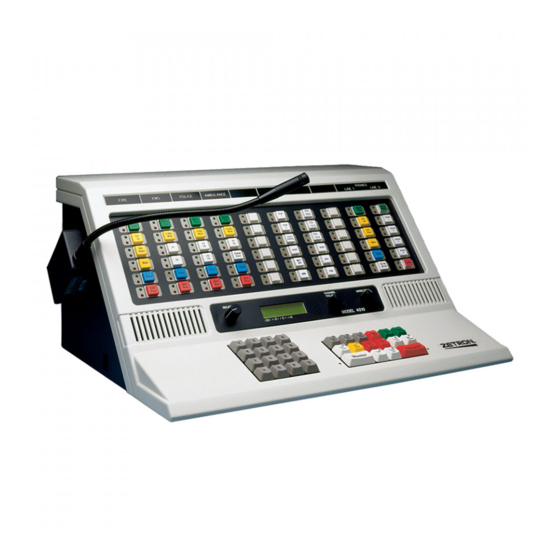
ZETRON 4010 Installation And Programming
Radio dispatch console
Hide thumbs
Also See for 4010:
- Service manual (123 pages) ,
- Programming manual (117 pages) ,
- Operation (38 pages)
Table of Contents
Advertisement
Quick Links
Download this manual
See also:
Service Manual
Advertisement
Table of Contents

Subscribe to Our Youtube Channel
Related Manuals for ZETRON 4010


Summary of Contents for ZETRON 4010
- Page 1 Model 4010 Radio Dispatch Console Installation and Programming 025-9227S...
- Page 2 Zetron Products or Zetron Accessories or refund the purchase price, at Zetron's option, after return of such items by buyer to Zetron. Shipment shall be paid for by the buyer. No credit shall be allowed for work performed by the buyer.
- Page 3 Warning! For your safety and the protection of the equipment, observe these STOP precautions when installing or servicing Zetron equipment: • Follow all warnings and instructions marked on the equipment or included in documentation. • Only technically qualified service personnel are permitted to install or service the equipment.
- Page 4 • Added caution about silkscreen labels in Dual Channel Card Jumpers and Switches on page 27. • Corrected the channels associated with J2, J3, and J4 in Model 4010 Main Control Board page 104. • Added to the description of Instant Call on page 127.
-
Page 5: Table Of Contents
Model 4010 Options ........ - Page 6 Model 4010 Phone Patch Card ........
- Page 7 Model 4010 T2-2R Base Station Installation ........
- Page 8 Model 4010 Main Control Board ..........104 Model 4010 Control Board Connectors and Fuse ....... 105 Model 4010 Display Board .
-
Page 9: Introduction
The Model 4010 may be tailored to fit the size of the system, from 2 to 12 radio channels, by adding dual channel cards as required. The channels can be configured to support a mix of control types: DC remote, tone remote, local control, and E&M control. - Page 10 Model 4010. Whereas the Model 4010 is a desktop console, the Model 4010R is a rackmount console designed to be mounted into a rack or furniture with a built-in rack mount compatible system. In this manual both the Model 4010 and 4010R are referred to as the Model 4010 unless specifically stated otherwise. 025-9227S...
-
Page 11: Manuals
Model 4010 and Model 4010R. Manuals Several manuals describe the operation, installation, service, and programming of the Model 4010. This manual describes the installation of the Model 4010. Below is a list of the manuals and a description of their contents. Part... -
Page 12: Specifications
Introduction Specifications Transmit Electrical Specifications Audio Output +10 dBm max. into 600Ω line Output Impedance Transmit: 600Ω balanced Idle: 600Ω or 3500Ω Distortion <2% at full output Signal-to-Noise > 50 dB Hum, Cross-Talk all -50 dB at full output Microphone Input -65 dBm for full output Headset Input -20 dBm for full output... -
Page 13: Console Power Requirements
Current 7 amperes AC Input 95 to 250 V , 47 to 63 Hz Approval Physical Specifications Model 4010 Size height = 9″ x width = 18″ x depth = 14″ inches Weight 15 pounds Model 4010R Size height = 10.5″ x width = 19″ x depth = 10.5″ inches... -
Page 14: Overview
The Model 4010 Radio Dispatch Console is a single position unit that has many built-in features. The Model 4010 is a desktop unit, and the Model 4010R is a rackmount unit. Both units have identical features and capabilities and are referred to as the Model 4010 in this manual unless specifically stated otherwise. -
Page 15: Installation Sequence
When planning, mounting, configuring, and wiring have been completed, the system is ready for its first installed test. The components have been tested at the Zetron factory, but it is necessary for you to perform a preliminary system check in order to verify the proper configuring and wiring. - Page 16 Operation During its initial operation, the system will operate according to the programming done at the Zetron factory. If you wish to alter operation through programming, see Programming on page 79. Changes in the programming may be performed by you once the system is installed.
-
Page 17: Console Installation
Overview Console Installation Overview The Model 4010 Communication Console is a self-contained unit, which makes for an easy installation. Accessories may be added to the console including headset jack box, desk microphone, handset (desktop unit only), gooseneck microphone, footswitch, and telephone/radio headset interface. -
Page 18: Important Notes
26 for setting the termination jumpers. Program/Run Switch The Model 4010 is programmed by sending a configuration file to it from a PC over a temporary serial connection. The configuration data is stored in write-protected memory, so writing must first be enabled by the program/run switch located on the bottom of the unit. -
Page 19: Power
Power Primary Power The Model 4010 requires an external 2.5 Ampere, 13.5 V regulated supply. The minimum input voltage of the console is 11.5 V and maximum of 15 V . -
Page 20: System Grounding
15 feet. The length of the runs should be minimized. Securely connect a grounding wire to the case of each unit making sure that a metal-to-metal connection is made (no paint or oxidation layer). Most Zetron equipment provides a grounding stud. Figure 5 shows a central star grounding system. -
Page 21: Slot Mapping
Usually the Zetron factory will prepare a slot map to your specifications, especially if you requested factory programming, since the map is required before the system can be programmed. - Page 22 You will notice several card slots designated J6-J12. Since the system is tested at the Zetron factory, you will find the channel cards already plugged into the assigned slots. Slots J12-J7 are for channel cards or Auxiliary I/O boards.
- Page 23 Slot Mapping Table 1: Slot/Card Compatibility Matrix Slot Card Compatibility Dual Channel Card, channels 1-2 Aux I/O Card Dual Channel Card, channels 3-4 Aux I/O Card Dual Channel Card, channels 5-6 Aux I/O Card Dual Channel Card, channels 7-8 Aux I/O Card Dual Channel Card, channels 9-10 Aux I/O Card Dual Channel Card, channels 11-12...
-
Page 24: Configuring Dispatch Consoles
See Model 4010 Dual Channel Card Layout on page 103 for the location of these jumpers. Table 2: Model 4010 Control Board Jumpers and Switches Jumper Options Notes Recorder Output & VU meter... -
Page 25: Model 4010 Options
There is a method to determine what options are enabled in a particular console. The Model 4010 has a programming switch located on the bottom of the console. Put the programming switch in the program position* for approximately one second and then return it to the normal run position while pressing the # key on the keypad. -
Page 26: Configuring Dual Channel Cards
Channel Type Each channel in the Model 4010 can be programmed to be one of three control types: Local, Tone, or DC. This programming is performed using CPSW software. Refer to Channel Configuration on page 85 for details. - Page 27 (or channel B on the card). See Table Caution! The cards in a Model 4010 are not hot swappable in the unit. You must power the unit off before any cards can be safely removed or added to the system.
-
Page 28: Line Termination
Standard HLGT Duration SW1-3-OFF SW1-7-OFF Duration on page 29. Custom HLGT Duration SW1-3-ON SW1-7-ON DC Current Control DC Current Control — Zetron standard levels SW1-3-OFF SW1-7-OFF Current Selection on page Motorola/GE currents SW1-3-ON SW1-7-ON Full Duplex (FD) FD disabled SW1-4-OFF... -
Page 29: Channel Cross-Mute
This is useful to prevent audio feedback between consoles present in the same room. If you need to cross mute more than three consoles, call ZETRON Technical Support for guidance. -
Page 30: Channel Vox Hang Time
Console Installation Channel VOX Hang Time The VOX signal is used to activate the unit CALL LED and to control patch transmission. The hang time of the CALL LED is programmable via CPSW, allowing the CALL indicator to remain on for a number of seconds after the actual voice activity ends. The hang time for patching is controlled by the channel or telephone card VOX circuit. -
Page 31: Wiring To The Channels
Wiring to the Channels Wiring to the Channels The radio channel interface is performed by the Dual Channel Cards. Each Dual Channel Card has terminations for two transmit/receive channels, known as Channels A and B. Each of the possible 12 channels in the system is referred to by a number; Channels 1-12. The channel numbers that a Dual Channel Card is controlling depends only on the card- slot into which the channel card is plugged. -
Page 32: Auxiliary Output
Console Installation Auxiliary Output This open-collector output pulls to ground when the standby-base feature for the channel is activated. This output will sink 500 mA to 0.8 V when active, and will withstand no more than 12 V when inactive. Ground is provided for the return path. Transmit Audio +/- This is the balanced source for transmit audio. -
Page 33: Equivalent Circuits
Wiring to the Channels Equivalent Circuits The figures accompanying Table 6 illustrate the interface signals’ equivalent circuits and the plug connections on which they may be found. All pin numbers listed in the following table refer to the 50-pin connectors on the rear of the unit and correspond to the terminal numbering on the punch-down blocks. - Page 34 Console Installation Table 7: Channel Plug Signals (J2, J3, J4) and 25-Pair Cable Colors Signal Wire Color Connector Wire Color Signal Chan A. PTT- White/Blue 26 -----------1 Blue/White Chan A. PTT+ Analog Ground White/Orange 27 -----------2 Orange/White Chan A. Recorder Out Digital Ground White/Green 28 -----------3...
-
Page 35: Split 50 66M Type Punch-Down Block
Split 50 66m Type Punch-Down Block Split 50 66m Type Punch-Down Block P/N 950-9351 Four Channels Chan A. PTT - — — — — Chan A. PTT + — — — — Analog GND — — — — Chan A. Record —... -
Page 36: Protected Punch-Down Block Configuration
Console Installation Protected Punch-Down Block Configuration MODEL 4010 INSTALLATION PROTECTED PUNCH-DOWN BLOCK MODEL OUTSIDE 4010 LINES SECONDARY PRIMARY PROTECTION PROTECTION OVERALL CONFIGURATION GROUNDING BUS INCOMING LINES _____________ Punch-Down Block P/N 950-9351 FOUR CHANNELS Chan A. PTT - Chan A. PTT + Analog Gnd Chan A. -
Page 37: Inputs And Outputs
Inputs and Outputs Inputs and Outputs The main board of the Model 4010 is equipped with eight inputs and outputs. These inputs and outputs can be used as auxiliary I/O, or as spare I/O. All inputs on the board must be one or the other (auxiliary or spare). -
Page 38: Outputs
Console Installation Outputs The Console has eight outputs, which can be programmed through CPSW. Outputs 1-4 are open collector drivers that can drive 0 to 25 V , 200 mA. Although the open collector outputs can each source 200 mA, only one collector output can be active at a time. If more than one is to be activated, the load should be no more than 100 mA. -
Page 39: Auxiliary Audio
Auxiliary Audio Auxiliary Audio The console has additional audio signals available on connector P1 at the rear of the unit. Most of these signals are used when installing optional equipment. The mating screw terminal connector is supplied with the console. The connector pinout is listed in Table Table 10: Auxiliary Audio Signal... -
Page 40: Model 4115B Connections
In this way, the data loops around from panel to panel in a daisy chain. Power is supplied to the expansion panel via the loop cable from the Model 4010. Each panel is also protected by a fuse labeled F2, which is accessible via the cutout in the rear panel. -
Page 41: Preliminary System Check
Configuration on page 83 for the proper procedure. 3. Change the display to show the time, date, and “Model 4010” by pressing the Diagnostic Reset key. If that key is not programmed, press any other key. The clock has been set at the factory for the Pacific Time Zone. The clock set function can be used to change the time if required. -
Page 42: Level Adjustments
Console Installation 4. Check the audible alarm by pressing any non-programmed key. The alarm (two beeps) is heard on the select speaker. 5. If the system is operating correctly up to this point, then make all necessary level adjustments. These adjustments are described in the next section. Level Adjustments Note Unless otherwise requested, receive, transmit, and transmit... -
Page 43: Microphone Adjustments
Level Adjustments provided with the 4010 when shipped to facilitate test point access. See Model 4010 Dual Channel Card Layout on page 103 for the location of P1. The P1 test points are: P1-1 Analog ground P1-2 CHB receive (RXB) -
Page 44: Auxiliary Audio Input Adjustment
If the Display Board is replaced or repaired, the following adjustment is required. Warning! Speaker DC bias is very sensitive. If adjusted incorrectly, the STOP speaker amplifiers can be damaged. Contact Zetron Technical Support for assistance. Display contrast, adjusted for best viewing Select speaker DC bias, adjusted for minimum DC voltage across select speaker (0 ±... -
Page 45: Tone Level Adjustments
Level Adjustments Tone Level Adjustments The tone generating circuit of the console generates the alert, paging, and warning tones. The alert tones are adjusted with the R67 (TONE) potentiometer. The maximum output level is limited by the input audio AGC circuit. The alert and paging tones are also sent to the operator select/unselect speaker and are adjusted with a potentiometer. - Page 46 Console Installation 025-9227S...
-
Page 47: Option Installation
Option Installation This chapter contains instructions for installing the following Model 4010 Console options: • Gooseneck Microphone on page 48 • Desk Microphone on page 49 • Footswitch on page 50 • Headset Jackbox on page 50 • Secondary Headset Jack Box on page 50 •... -
Page 48: Gooseneck Microphone
Option Installation Gooseneck Microphone The Gooseneck Microphone (P/N 950-9314) may be used with the Model 4010 Console. When installed in the field, the microphone will come with an adapter box to provide a base for the mounting of the microphone. -
Page 49: Desk Microphone
Desk Microphone Desk Microphone Zetron desktop microphones are wired directly to the consoles. Identify which microphone you have in Figure 8 and wire it to the console’s P1 Aux Audio connector pins as identified in Table 12. P1 Aux Audio is located at the rear of the console. -
Page 50: Footswitch
The Zetron Series 4000 Secondary Headset Jack Box (SHJB), P/N 950-9208, is designed to allow multiple headsets to be simultaneously connected to the Model 4010 radio control console. The SHJB is low profile and is intended for mounting under the writing surface of an operator’s station. -
Page 51: Installation
Secondary Headset Jack Box Installation Installation requires mounting the SHJB, selecting interface operation via jumpers, wiring the SHJB to the radio control console, wiring the jack box to other parallel jack boxes, and optionally wiring the jack box to a footswitch. Mounting The SHJB can be mounted anywhere desired, but most frequently, it is installed under the writing surface of the dispatch furniture. - Page 52 Wiring to Zetron Console The Secondary Headset Jack Box is easily plugged into the Model 4010. The 9-pin, D- type connector, J2 (console), at the rear of the jack box provides the signals to the console. The supplied 9-pin cable should be used to interconnect the jack box port J2 to the console at the headset connector J1.
-
Page 53: Telephone/Radio Headset Interface
The Zetron Series 4000 Telephone-Radio Headset Interface (TRHI) (P/N 950-9439) is designed to allow one common headset to be used for both the Model 4010 radio control console and a telephone instrument. It should not be confused with the Headset Jack Box (P/N 950-9327) which merely provides a jack for the Model 4010 console. -
Page 54: Model 4010 Phone Patch Card
Contact Zetron for more information. Installation The Phone Patch card is installed in the last slot of the Model 4010 chassis. Open the console by unscrewing the two latches on the back of the console and lifting the top open. -
Page 55: Programming
The following buttons are typically used for phone channels: Answer Hold (Off-Hook), Release (On-Hook), Switch Hook Flash, Mute, Volume Adjust, and Patch. See the Model 4010 Operator’s Manual (P/ N 025-9226) for details on these buttons and other operating information. -
Page 56: Model 4010 Auxiliary I/O Card
Model 4010 Auxiliary I/O Card The Auxiliary I/O Board, 702-9448, may be installed in any dual channel slot in the Model 4010 to add additional input and output capability. Each card adds six double ended outputs and six single ended inputs. -
Page 57: Auxiliary Inputs
Model 4010 Auxiliary I/O Card Table 14: Auxiliary Output Configuration Jumpers Output # Jumpers Output 1 JP1 and JP7 Output 2 JP4 and JP10 Output 3 JP6 and JP12 Output 4 JP2 and JP8 Output 5 JP3 and JP9 Output 6... -
Page 58: Programming
Option Installation Table 15: Auxiliary Output Jumpers Explained Relay Contact Configuration Jumper Pair JPY Jumper Pair JPX Relay off, A & B signals open Relay on, A & B signals connected Relay off, A & B signals connected Relay on, A & B signals open Relay off, A signal open, B signal grounded Relay on, A signal grounded, B signal open Programming... -
Page 59: Connector Pinout
I/O assignment of the existing board will have to be changed via CPSW to match the new I/O numbers assigned to it by the Model 4010 software. Connector Pinout The location of the auxiliary signals depends on which channel slot the Auxiliary I/O Board is installed in. - Page 60 Option Installation Table 19: Signal vs. Pin Assignment — Lower Half Signal Signal open Input 1 Analog GND Input 2 Ground Input 3 open Input 4 RLY1B RLY1A RLY2B RLY2A RLY3B RLY3A Ground Input 5 open Input 6 RLY4B RLY4A RLY5B RLY5A RLY6B...
-
Page 61: Split 50 66M Type Punch-Down Block
Model 4010 Auxiliary I/O Card Split 50 66M Type Punch-Down Block P/N 950-9351 FOUR CHANNELS OPEN — — — — INPUT 1 — — — — ANALOG GND — — — — INPUT 2 — — — — GROUND — — — —... -
Page 62: Model 4010 Tone Remote System Adapter
One of the Tone Remote System Adapters (P/N 950-0255, or 950-9922) is required for the Model 4010 to transmit to a tone controlled radio. The adapter has a 2175-Hz oscillator to generate the required guard tone and has 2175-Hz filters to remove the low-level guard tone from the received audio. -
Page 63: High Level Guard Tone Timing
Model 4010 Tone Remote System Adapter High Level Guard Tone Timing The high level guard tone (HLGT) duration has a standard setting of 120 milliseconds when the channel OPT switch is in the OFF position. The HLGT duration may be selected in the system configuration when the OPT switch is in the ON position. -
Page 64: Model 4010 Dc Remote Daughter Board
Installation The cover of the Model 4010 must be raised by unscrewing the two thumbscrews on the back of the unit and lifting the top. -
Page 65: Dc Current Calibration
The pot (R15) is accessible from the top of the unit (with Model 4010 cover open) and, with a current meter in series with the transmission line, can be adjusted to the desired level. The factory adjustment is for 0.5-milliampere programmable steps. -
Page 66: Model 4010 Tone Lotl Daughter Board
(console or station remote) controlling it. Installation The cover of the Model 4010 must be raised by unscrewing the two thumbscrews on the back of the unit and lifting the top. Caution! Keep the front of the unit on the tabletop;... -
Page 67: Model 4010 Channel Ani Decoder
Next, observe the first two non-blank characters immediately to the left of the firmware version number. They should be “nx”, where x is the number of ANI decoders installed. If x is the correct number of decoders, your Model 4010 is ready to detect ANI on the... -
Page 68: Configuration
ANI board and will not communicate with it. Make sure the ANI board is properly installed, reset the Model 4010 by cycling power, and try again. If the display still indicates “N0” or the wrong number of ANI decoders, contact Zetron. -
Page 69: Model 4010 Parallel Status Option
Model 4010 Parallel Status Option Model 4010 Parallel Status Option When two Model 4010 consoles control the same radio transmitter, the Parallel Status Option communicates the frequency information between the consoles. The Busy Out and Busy In signals of the two associated channels also need to be connected together so the consoles reflect the transmit status of the channel. -
Page 70: Console Programming
The console must be programmed using the Console Programming System (CPSW) to enable the Parallel Status option. If the console is ordered with the Parallel Status option, it is programmed at Zetron. Refer to Miscellaneous on page 99 for programming information. - Page 71 Model 4010 Parallel Status Option Figure 10: Split 50 66M Punch-Down Block (P/N 950-9351) for the Parallel Status Option FOUR CHANNELS Chan A. PTT - 26 Chan A. PTT - — — — — Chan A. PTT + 1 Chan A. PTT + —...
-
Page 72: Ge-Star Decoder
Option Installation GE-Star Decoder The ZETRON Model 4010 GE-STAR Decoder is designed to add on to any existing ZETRON Model 4010 Dual Channel Card. The GE-STAR Decoder can be configured to interpret one of a number of different GE-STAR formats. The DIP switches 1-4 on the GE-STAR Decoder board determine the format that will be decoded. -
Page 73: Error Indications
ID. Output Format The M4010 ZETRON GE-STAR Decoder output will display on the console as a sequence of characters and numbers that represent the decoded GE-STAR ID. The displayed ID starts with either a number sign (#) for non-emergency ID’s or a star (*) for... - Page 74 Option Installation Table 26: 11-Bit and Extended ID Decoding Output Description #xxxxS Status Message (where S=0-7) #xxxxB Request to Talk ID #xxxxC Stuck Mic ID #xxxx PTI ID *xxxx Emergency ID *xxxxD Man Down ID where xxxx = decoded GE-STAR ID: 0000-2047 w/11-bit decoding 0000-4095 w/12-bit decoding 0000-8191 w/13-bit decoding...
-
Page 75: Model 4010 T2-2R Base Station Installation
Model 4010 T2-2R Base Station Installation Model 4010 T2-2R Base Station Installation There are two methods of installing a T2-2R base station to a Model 4010 Console. Method 1 This method allocates one system channel to the T2-2R base station. - Page 76 Option Installation Figure 12: T2-2R installation method 2 Base Station Dual Channel Card 2-Wire TX/RX First Transmitter Frequency Channel B Receiver (F2 RX) Second 4-Wire RX Frequency (see note) Receiver Busy Output Busy/Mute Input Channel B Configuration: 2-wire termination = low impedance Busy Output Configuration switch 2 (x-mute) = On Busy/Mute Input...
-
Page 77: Ptt Handset With Cradle
PTT Handset with Cradle PTT Handset with Cradle The PTT Handset (P/N 950-9315) may be used with the Model 4010 Console. When installed in the field, the handset cradle must be mounted to the side of the console using the four mounting holes provided. See Figure 13 for details. - Page 78 Option Installation 025-9227S...
-
Page 79: Programming
The CPSW executable can be run to support the Model 4010, or the Model 4116B and 4018/4118. This chapter provides instruction for CPSW for the Model 4010 only. The following table can help you identify the correct documentation for your model. -
Page 80: Firmware Compatibility
CPSW uses the standard Windows procedure for uninstallation. 1. From the Windows Control Panel, double-click Add/Remove Programs. 2. In the alphabetical list of installed programs, find and click Zetron CPSW to select it. 3. With Zetron CPSW selected, click Remove (located on the same highlighted line). -
Page 81: Cpsw Menu Structure
CPSW Menu Structure CPSW Menu Structure The following two figures provide a map for all menu items in CPSW. Figure 14 shows all menus items except key definitions. Figure 15 shows menu items related to key definitions. Note When using CPSW, several menu items may be unavailable if they are incompatible or not relevant based on other configured settings. - Page 82 Programming Figure 15: CPSW Menu Structure (continued) Previous page Define Erase Move Copy Map to Spare Channel Functions Select Answer/Hold TONE Frequency Select Volume Adjust +2.5 mA 650 Hz Freq. Select w/Voting Mute Adjust +5.0 mA 750 Hz Instant Select Volume Up +7.5 mA 850 Hz...
-
Page 83: Using Cpsw
CPSW Menu Structure Using CPSW This chapter describes how to configure Model 4010 dispatch consoles. This is accomplished through three primary tasks: 1. Use one of the following methods to get configuration settings: a. Download an existing configuration from a console... - Page 84 Zetron equipment. 2. There is an unlabeled switch on the bottom of the Model 4010 used to switch the console between RUN and PROGRAM modes. Move the switch to the program position, which is towards the gooseneck MIC and away from the DATA IN, DATA OUT, and COMB jacks.
-
Page 85: Editing A Configuration
3. Double-click the appropriate .cf1 file. Once loaded, the system name of this configuration appears in the window’s title bar adjacent to “CPSW” and the CPSW version number. When ZETRON prepares the configuration file, the system name is also the first seven letters of the filename. - Page 86 Programming 4. Select the Channel Type. Channel Description Type DC Control Use this DC control option if the radio requires only a momentary DC current to Momentary perform the desired function. DC Control Some radios require that the control current be maintained constant in order to Constant perform the desired function.
- Page 87 CPSW Menu Structure Control Description Protocol T4R4 Four-frequency tone controlled remote radio without PL. Refer to DC and Tone Without PL Remote Function Definitions on page 110 for a list of the frequencies generated. T8R8 This is an eight-frequency tone controlled remote radio. Refer to DC and Tone Remote Function Definitions on page 110 for a list of the tones required to...
- Page 88 Programming Paging Format Configuration Each paging format to be used in Model 4010 consoles must have certain parameters unique to that format defined and must have a leading digit assigned to it. There are 14 leading digits available to be assigned among the nine different paging formats the console is capable of generating (some of which are optional).
- Page 89 (4) Fast warble alert For example, assuming the “Alerts” paging format has been assigned to leading digit “A”, keying A4 on the Model 4010 paging/DTMF keypad enters the Fast Warble alert on the paging stack. Beep Alert (0) and Delay (D) function are configurable: •...
- Page 90 Click Delete. Input/Output Configuration The main board of the Model 4010 is equipped with eight inputs and outputs. These inputs and outputs can be used as auxiliary inputs and outputs, or as spare inputs and outputs. All inputs on the board must be one or the other (auxiliary or spare). All outputs must be one...
- Page 91 • The number of auxiliary inputs and outputs can be increased by adding Aux I/O Cards (see Model 4010 Auxiliary I/O Card on page 56). Each Aux I/O Card has six inputs and six outputs, and you can add up to five Aux I/O Cards. For more...
- Page 92 Programming 6. Proceed with the following procedure to label auxiliary I/O, or click Done if you are finished. To define a key Note To define spare inputs and outputs, see on page To map 95. To configure a spare input to activate a defined key, see a key to a spare input on page 96.
- Page 93 CPSW Menu Structure ♦ To configure the priority marker 1. Click Edit, System Configuration, Priority Marker. 2. Set the Priority Marker Frequency (600 to 2000 Hz). This sets the tone frequency of the beep. 3. Set the Priority Marker Duration (50 to 2000 ms). This sets the duration of the beep.
- Page 94 Programming It is best to configure system settings before position settings. Some position settings, such as specific key definitions, are not available until the system settings are configured correctly. See System Settings on page 85. Position Layout The layout of button panels can vary from position to position. ♦...
- Page 95 CPSW Menu Structure 3. Click Apply. 4. Click Yes to confirm. ♦ To move or swap a key definition 1. Click Move. 2. Click a key to select its definition for moving. This is the “source” key. (If you are swapping key definitions, it does not matter which key you select first.) Once selected, the key is outlined in blue.
- Page 96 Programming 3. There are approximately 130 functions that can be configured in this dialog box. All settings are grouped by the key’s functional group. a. To assign a channel function to this key, select Channel Functions from The Key’s Functional Group. The channel functions group includes all functions specifically related to a channel.
- Page 97 CPSW Menu Structure 3. Configure the audio control settings as needed. The following table explains each setting: This number (0 to 99) represents the percentage of total volume to be used Muted Audio Level * as a muted audio level for all channels of the position. This number (0 to 99) represents the percentage of total volume to be used Minimum Audio Level * as a minimum adjustable audio level for all channels of the position.
- Page 98 Programming 3. Configure the ANI decode settings as needed. The following table explains each setting: Operating Mode Select the desired operating mode: • No ANI Display - ANI is not displayed on this position. • Selected Channels - ANI is displayed at this position for select channels only.
- Page 99 22299 Nothing Note The Model 4010 is able to decode only the unit identification in a PTT-ID. ANIs that are configured with fleet or group designation separated by a dash from the unit ID cannot be displayed on the 4010 LCD. Therefore, end users who have multiple fleet/group IDs...
-
Page 100: Saving A Configuration
‘Soft’ transmit keys: • Dynamic Mic - Use a deskmic connected to the D-Mic input on the console Aux Audio Connector P1, or a Gooseneck Mic connected to the 4010 Main Control Board at P12. • Electret Mic - Use a handset or headset. -
Page 101: Sending A Configuration To A Console
Zetron equipment. 2. There is an unlabeled switch on the bottom of the Model 4010 used to switch the console between RUN and PROGRAM modes. Move the switch to the program position, which is towards the gooseneck MIC and away from the DATA IN, DATA OUT, and COMB jacks. - Page 102 If the name of the file has fewer than eight characters, the LCD may display extra characters. 8. If you need to send the same configuration settings to more than one 4010 console, repeat this procedure as needed.
-
Page 103: Appendix A: Model 4010 Components
Model 4010 Dual Channel Card Layout Appendix A: Model 4010 Components Model 4010 Dual Channel Card Layout Model 4010 (P/N 702-9377) On older boards, P1 and JP6 may be located in different positions than shown here. P2 and P3 are used to mount daughterboard such as the LOTL or Channel ANI Decoders. -
Page 104: Model 4010 Main Control Board
Appendix A: Model 4010 Components Model 4010 Main Control Board Model 4010 (P/N 702-9376) Model 4010R (P/N 702-9569) Handset Cradle Hook Switch 025-9227S... -
Page 105: Model 4010 Control Board Connectors And Fuse
Model 4010 Main Control Board Model 4010 Control Board Connectors and Fuse For a list of jumpers and switches, see Model 4010 Control Board Jumpers and Switches on page 24. For a list of pots, see Level Adjustments on page 42. For a list of connectors, see the following table. -
Page 106: Model 4010 Display Board
(P/N 702-9378) Unselect Speaker Select Speaker Table 30: Model 4010 Display Board jumpers and pots Adjusts the backlight brightness to low (L), medium (M), or high (H). The default setting is H. Adjusts the minimum volume of the unselect speaker. Older units may have a different pot number, but the pot is located in the same location. -
Page 107: Model 4010 Tone Remote Adapter
Model 4010 Tone Remote Adapter Model 4010 Tone Remote Adapter PATCH DLYD With audio delay (P/N 702-9896) JP2 JP3 TP1 DELAY Without audio delay (P/N 702-9433) AUDIO... - Page 108 JP6 (MIC) Enable notch filter Disable notch filter The default conditions for the jumpers are in the IN position and .75 seconds for the delay setting. For additional information, see Model 4010 Tone Remote System Adapter on page 62. 025-9227S...
-
Page 109: Appendix B: Cpsw Reference Material
Appendix B: CPSW Reference Material This appendix contains reference material used for programming with CPSW (Console Programming System for Windows). See Programming on page 79. Main topics in this appendix: • DC and Tone Remote Function Definitions on page 110 •... -
Page 110: Dc And Tone Remote Function Definitions
Appendix B: CPSW Reference Material DC and Tone Remote Function Definitions Table 32: DC Remote Function Definition T1R1 T1R1 Current T2R2 T4R4 PAGING 0.0 mA +2.5 mA — — — — +5.0 mA — +7.5 mA — — — — +10.0 mA —... -
Page 111: Achieving Motorola/Ge Dc Control Currents
Achieving Motorola/GE DC Control Currents Achieving Motorola/GE DC Control Currents Normally, the available positive and negative currents which are based on 2.5 mA increments will achieve proper control of DC Remote Controlled base stations. However, a feature on the late DC Dual Channel Cards allow the exact Motorola and GE currents to be achieved. -
Page 112: Paging Format Specifications
Appendix B: CPSW Reference Material Paging Format Specifications Table 34: Motorola and GE Tone Group Frequencies Tone Tone Groups Number Mot 1 Mot 2 Mot 3 Mot 4 Mot 5 Mot 6 Mot A 330.5 569.1 1092.4 321.7 553.9 1122.5 358.9 349.0 600.9... - Page 113 Paging Format Specifications Table 35: Motorola and GE Code Plans Pager Code Plans Cap- Mot B Mot C Mot D Mot E Mot F Mot G Mot H Mot J Mot K code Groups Groups Groups Groups Groups Groups Groups Groups Groups Groups...
- Page 114 Appendix B: CPSW Reference Material Table 36: General Encoding Plans Pager General Plan Modified Gen. Plan General Alternate Plan Cap- Tone Diagonal Tone Diagonal Tone Pager code Groups Tone Groups Tone Groups Capcode 569.1 569.1 953.7 + Mot 1 979.9 979.9 953.7 + Mot 2 569.1...
- Page 115 1553.0 892.0 512.0 2612.0 1500.0 862.0 495.0 2523.0 1449.0 832.0 2437.0 1400.0 804.0 2354.0 1352.0 776.0 Table 38: Zetron Tone Groups for Reach Encoding Tone Tone Groups Number 1980.0 1177.0 1400.0 832.0 588.0 2704.0 1608.0 1912.0 1137.0 804.0 2612.0 1553.0 1847.0...
- Page 116 Appendix B: CPSW Reference Material Table 39: Reach Code Plan Individual Call Pager Tone Groups Capcode (x+y) Z5+Z3 Z1+Z2 Z2+Z1 Z3+Z4 Z4+Z3 Z1+Z4 Z4+Z1 Z1+Z5 Z5+Z1 Z3+Z5 Note The ones/tens digit encoding, shown by “x” and “y,” reverses position for each 100 pager block. In Motorola/GE plans, the first tone is always the tens digit and the second tone is the ones digit.
- Page 117 Paging Format Specifications Table 40: Zetron Standard Tone Sets Tone Set CCIR ZVEI DDZVEI DZVEI PZVEI Tone No. 0 1981 1981 2400 2400 2200 2400 Tone No. 1 1124 1124 1060 1060 1060 Tone No. 2 1197 1197 1160 1160...
- Page 118 Appendix B: CPSW Reference Material Key from 16-button keypad. Timing: Variable. Typical is 150ms of tone, 50ms of silence. Digits: 1 through 14, including A, B, C, D, *, and #. Table 42: Quick Call One (Two-Plus-Two) Frequencies and Timing Tone A Series B Series...
-
Page 119: Description Of Key Functions And Parameters
Description of Key Functions and Parameters Description of Key Functions and Parameters This section describes key functions and their definable parameters. Use this section as a reference when defining key functions (see To define a key on page 95). Channel Functions To define a channel function, you must first select the channel number. - Page 120 Appendix B: CPSW Reference Material Instant Select Instant Select differs from the normal Select function in that after the Select is performed, a DC or Tone control function is sent. This is normally used on a multi-frequency base station to select a channel at a desired frequency. Several Instant Select keys may be assigned to a single channel even though only one can be active at a time.
- Page 121 Description of Key Functions and Parameters the volume to be adjusted upwards. Releasing the key will cause the volume to be set to the displayed level. The red key indicator will illuminate while the key is pressed. Volume Down (Key) This key is assigned to a specific channel to allow “one hand”...
- Page 122 Appendix B: CPSW Reference Material Monitor This key will send the correct command (current or tone) to disable the private line or channel guard feature of the radio allowing the received audio to be heard at the console. The indicator LED will remain on until the channel's transmitter is keyed. Phone On/Off Hook This key will activate the auxiliary output line of the designated channel.
-
Page 123: System Functions
Description of Key Functions and Parameters Wild Card I On/Off Toggle the Wild Card I function on the appropriate tone controlled radio channel. Refer to DC and Tone Remote Function Definitions on page 110 for the function actually transmitted. Wild Card II On/Off Toggle the Wild Card II function on the appropriate tone controlled radio channel. - Page 124 Appendix B: CPSW Reference Material Last Call Transmit Any Channel This key will cause the last channel that received audio (“Call” activity) to transmit. The channel will not be selected. Last Call Transmit Selected Channels This key will cause the last “Selected” channel that received audio (“Call” activity) to transmit.
- Page 125 Description of Key Functions and Parameters groups. If a channel card is not installed in the system, its channels will not show in the table. If the channel chosen is tone or DC and is defined as a multi-frequency channel, you will be asked to select the desired function (tone or current) to be used when this key is activated.
- Page 126 Appendix B: CPSW Reference Material Diagnostics Reset By programming this key, any diagnostic messages displayed on the console will be held until the key is pressed. If this key is not assigned, the diagnostic will be removed after approximately three seconds or when the next key is pressed. Clock Set By programming this key, clock setting can be initiated by pressing the “CLOCK SET”...
- Page 127 Description of Key Functions and Parameters Paging Keys Note The “Instant Call” and “Page Safety” functions represent optional features. They can always be programmed, but will generate an error message in the console if the Instant Call Paging option has not been installed.
-
Page 128: Auxiliary Input/Output
Appendix B: CPSW Reference Material them. If this key has not been programmed, pressing an instant-call page key will begin the page transmission immediately. Burst Tone Select A 1-second tone burst can be enabled by selecting a frequency from the list. This tone burst is generated for each transmit function after the transmitter is keyed-up and before the console audio is switched on. -
Page 129: Configuration On
Card(s) (P/N 702-9448) as follows: 9-14 to the first Aux. I/O Card, 15-20 to the second Aux. I/O Card, etc. This allows the Model 4010 to support up to five Aux. I/O Cards for a total of 30 ports. Auxiliary Output Port numbers 9-38 are assigned to the optional Expanded Aux. - Page 130 Appendix B: CPSW Reference Material Auxiliary Output Interlocked Several outputs may be “interlocked” such that only one output can be active at any given moment. That is, when one output goes active, all others will be inactive. Up to 32 interlock groups may be defined with any number of outputs per group.
-
Page 131: Appendix C: Maintenance
Battery Check/Replacement The Model 4010 relies on battery backup to keep the configuration stored in memory. This battery, contained within a socket, has a life expectancy of 4-7 years. Zetron recommends replacing the battery at a minimum of every 5 years. You can check the battery voltage using the following procedure, which requires a voltmeter. -
Page 132: Display Board Adjustment
Model 4010 Display Board on page 106 for a board diagram. 1. Turn on the Model 4010 and check the LCD display for contrast quality. Adjust R21 on the Display Board for the best contrast. 2. Disconnect the Select Speaker from JP3. -
Page 133: Appendix D: Troubleshooting
103). A short-term fix is to remove the Tone Remote System Adapter, clean the P4 pins, and reseat the adapter. A long-term fix is available in the form of a gold-pin upgrade. Contact Zetron for more information. Erratic behavior on 4-year or older consoles Check the battery. - Page 134 Appendix D: Troubleshooting 025-9227S...
-
Page 135: Index
DC Remote Daughter Board , 39 Button labeling , 49 Desk Microphone , 49 desktop microphone , 126 Diagnostics Reset button Display Board , 67 Channel ANI Decoder , 106 4010 , 85 Channel Configuration , 99 Display Operation , 29 Channel Cross-Mute... - Page 136 Index , 117 DTMF frequencies and timing , 27 Dual Channel Card jumpers and switches , 50 Jackbox , 103 Dual Channel Card Layout , 26 Dual Channel Cards , 94 Key Definitions , 119 Key Functions and Parameters , 33 Equivalent Circuits wiring , 122 Extended Channel Functions...
- Page 137 Reach code plan Spare Output Latching button , 115 , 44 Reach encoding plan Speaker minimum audio level , 115 , 125 Zetron tone groups for Reach encoding Speaker/Headset button , 117 , 12 Zetron tone sets Specifications , 112 , 41...
- Page 138 Index , 32 , 120 Transmit Audio wiring Volume Adjust button , 123 , 120 Transmit Keys Volume and Mute Keys , 92 , 121 Transmit Timeout Volume Down button , 53 , 121 TRHI Volume Mute button , 133 , 124 Troubleshooting Volume Reset button...
Need help?
Do you have a question about the 4010 and is the answer not in the manual?
Questions and answers