
Subscribe to Our Youtube Channel
Related Manuals for MB QUART STAGE 5


Summary of Contents for MB QUART STAGE 5
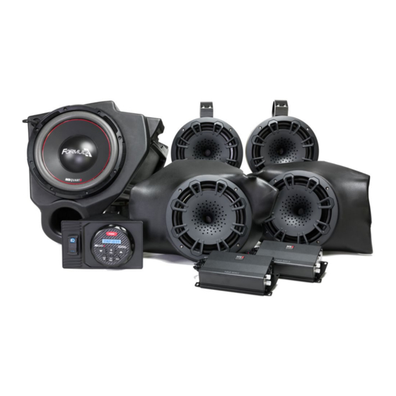
- Page 1 Installation Manual MBQ-STG5-1 STAGE 5 800 WATT / FIVE SPEAKER RZR-Tuned Audio Package...
- Page 2 Thanks for choosing MB QUART! The RZR-Tuned Stage 5 Audio System has been meticulously engineered for your vehicle. The process is simple and straightforward. Installation following these detailed instructions can be completed in about 3.5 hours. INSTALLATION OVERVIEW VIDEO Many of our vehicle-specific products feature a “how to”...
-
Page 3: Safety Precautions
INSTALLATION TIME About 3.5 hours are required to complete this installation. TOOLS AND SUPPLIES NEEDED ● Wire Strippers and Crimpers ● Blue Painter’s Tape and Marker Pen ● Flush Cut Wire Cutters (for trimming zip ties) ● Small (Jeweler’s) Screwdriver ●... - Page 4 STEP 2 - PREPARE KICK PANEL COMPRESSION HORNS Figure 2-1 is from the MBQ-POD manual which guides you Figure 2-1 step-by-step through preparing the kick panel compression horn speakers for installation into the kick panel enclosure and the RZR. Removing the large back plate and installing the special compression horn diaphragm covers dramatically reduces the depth of the compression horns which ultimately allows our overall kick panel enclosure to be shallower than you...
- Page 5 INSTALL SUBWOOFER INTO ENCLOSURE STEP 1 - WIRING THE SUBWOOFER* Set your subwoofer enclosure on a flat surface as shown in Figure 4-1. *If you have a 2018.5 Turbo S or 2019 RZR model, please see the modification required on the next page BEFORE completing the subwoofer installation into the enclosure.
- Page 6 REMOVE & REINSTALL THE GLOVE BOX DOOR With a small amount of pressure you can bend up on the center portion of your OEM glove box door and remove it from the brackets. In a reverse movement you can now reinstall this door onto your new subwoofer glove box to give your subwoofer a stealth appearance as shown in Figure 5-1.
- Page 7 DASH AREA DISASSEMBLY 2013-2018 (Non-Turbo S) RZR Please note, separate disassembly instructions for the 2018.5 Turbo S and 2019 RZR models are found on pages 9-11 in this manual. Figure 6-1 STEP 1 – REMOVE CENTER HOOD Start with removing the hood as shown in Figure 6-1. Twist the tabs at the upper left and right corners.
- Page 8 DASH AREA DISASSEMBLY 2013-2018 (Non-Turbo S) RZR - Continued STEP 5 – REMOVE DASH FASCIA CENTER HARDWARE Remove (4) Torx screws from the front of the dash through the openings shown in Figure 6-5a. The first set of Torx screws will come out allowing access to the second (upper) set further back in the dash. Next, pull the only the center of the dash loose as shown in Figure 6-5b.
- Page 9 DASH AREA DISASSEMBLY 2018.5 Turbo S & 2019 RZR Please note, separate disassembly instructions for the 2013-2018 RZR models are found on pages 7-8 in this manual. STEP 1 – REMOVE CENTER HOOD Figure 7-1 Remove the center of the hood area as shown in Figure 7-1.
- Page 10 DASH AREA DISASSEMBLY 2018.5 Turbo S & 2019 RZR - Continued STEP 4 – REMOVE DYNAMICS ECU BRACKET* AND POCKET SCREW Remove (4) 10mm bolts holding the Dynamics ECU bracket as shown in Figure 7-4a. Move the ECU to the side leaving wire connection intact.
- Page 11 DASH AREA DISASSEMBLY 2018.5 Turbo S & 2019 RZR - Continued STEP 7 – PREPARE FINAL ELECTRONICS FOR DASH REMOVAL Gently remove the plastic nut holding the ignition switch to the dash as shown in Figure 7-7a. Next, disconnect wires from back of switches as shown in Figure 7-7b. Take note of plug color and switch location for reassembly purposes.
- Page 12 REMOVE SEATS AND CENTER CONSOLE (ALL MODELS) STEP 1 – REMOVE SEATS Remove driver and passenger seats by pulling on the lock clip shown in Figure 8-1. This lock clip is located between the bottom and upright portion of the seat. Behind the seats in the center of the machine is the panel where you access the oil filter.
- Page 13 INSTALL POWER HARNESS AT BUSBAR (ALL MODELS) Before positing the system harness and wiring all the components (source unit, amplifiers, subwoofer and other speakers), you need to prepare the power portion of the audio harness and run into the vehicle. STEP 1 –...
- Page 14 Before installing the dual amplifier plate with the amplifier(s) in position, you must prepare the mounting area in the vehicle to accept the plate. NOTE - These instructions assume both amplifiers and all speakers are present in a full Stage 5 System. If not all components are present in your system, this makes upgrading much easier.
- Page 15 If a factory-optioned amplifier was present, this would also have been removed. NOTE - These instructions assume both amplifiers and all speakers are present in a full Stage 5 System. If not all components are present in your system, this makes upgrading much easier.
- Page 16 SUBWOOFER ENCLOSURE MOUNTING (ALL MODELS) With the subwoofer installed in the enclosure and the glove box door in position from earlier preparation steps, you are ready to mount the subwoofer into the glove box location. For those applications on 2018.5 Turbo S and 2019+ RZR models, ensure you’ve completed the modification shown on page 6.
- Page 17 AMPLIFIER AND SPEAKER WIRING HARNESS CONNECTIONS With your amplifier(s) mounted, subwoofer installed and connected to the mono amplifier, you can now begin laying in the front/rear speaker harnesses and plugging in all the remaining connectors. NOTE - While you are working on your system, we recommend covering the amplifiers to avoid scratching them or inadvertently hitting the crossovers with a wrench or screw driver.
- Page 18 REAR SPEAKER POD INSTALLATION Every roll cage angle is a bit different; therefore you should take the time to install the swivel mount brackets. We suggest you do this on a flat surface or work bench. These brackets are designed to allow 180 degree tilt. This guaranties that the speaker points directly forward.
- Page 19 MOUNTING THE KICK PANEL SPEAKERS Through hundreds of installations, we’ve found once mounting holes are drilled, it’s best to start with the driver’s side kick panel and then move on to the passenger’s side kick panel to complete the mounting and wiring of the kick panels.
- Page 20 STEP 4 – MOUNT KICK PANELS Using the 5/16 inch bolts, washers, and nuts, mount the kick panel as shown in Figure 14-4. Make sure you use a washer on the inside of the enclosure against the internal wall of the pod which you sandwich against the fender of the RZR.
- Page 21 MBQ-SUBSYS-1 Bass Boost to 0dB This manual assumes the full Stage 5 System and provides the information for initial settings accordingly. STEP 1 – ADJUST TWO-CHANNEL AMPLIFIER Looking at the NA2-400.2 shown in Figure 15.1, make the following initial adjustments: Figure 15-1 ●...
- Page 22 SOURCE UNIT PREPARATION This applies to non-Ride Command-equipped vehicles. If your RZR is equipped with the Ride Command system, you will use that as the vehicle’s source unit and this requires additional purchase of two adapters (part number RC1-2RCA-F ) to provide signal and turn-on to the MB Quart amplifiers. The MB Quart source unit is not required to be used in Ride Command-equipped applications.
- Page 23 INSTALLING THE SOURCE UNIT (Non-Ride Command-Equipped) Reassemble part of the front dash around the dash pocket area. Utilize the reverse method of how you removed the center section of the dash pocket. This will allow the source unit mount to be to be installed in place so the harness can be finished and connected in the proper location.
- Page 24 MOUNT THE USB & 3.5mm (AUX) DASH ADAPTER Every machine and more importantly every RZR owner is different. With the STAGE Tuned Audio packages, we include a dual input dash adapter. This means that no matter how you connect your audio system or which RZR you have, you have plenty of connections.
- Page 25 INITIAL TESTING Nearly done, but it is smart to confirm that everything is working before you put the machine back together. STEP 1 – RECONNECT THE BATTERY Figure 19-1 With the harness connected to the busbar, you can now reconnect the negative terminal of the negative battery cable as indicated in Figure 19-1.
- Page 26 FINE TUNING After you have confirmed and tested that all components are working you will tune the amplifiers. When setting up your amplifiers you will refer to the manual inside each amplifier. However, through hundreds of installations we have determined the following settings are ideal for the following STAGE Tuned Audio Packages.
- Page 27 FINAL AMPLIFIER MOUNTING (2018.5 Turbo S & 2019 Models) Now that the system is tested and tuned, if you have a 2018.5 Turbo S or 2019+ model RZR, you’ll now be ready to finalize the amplifier mounting and complete the install.This will be much like the earlier trial fitting on page 15, but the hardware will be fully tightened and the wiring zip tied neatly in place.
- Page 28 ● TIGHTEN NUTS ON STEERING WHEEL COLUMN (2013-2018 Models) - 40 FT/LB of TORQUE* ● FRONT OF DASH - CHECK ALIGNMENT WHERE THE DASH MEETS THE SUBWOOFER ● ZIP TIE STAGE 5 WIRING HARNESS WHILE AVOIDING HEAT SOURCES OR MOVING PARTS ● REASSEMBLE TOP OF DASH ●...
- Page 29 FINAL INSPECTION Here is a check list to make sure your vehicle is ready to hit the trails. You should pull & tighten everything so that you know your RZR and your audio equipment are secure. ● NUTS ON HARNESS AT THE BUSBAR ●...
- Page 30 COMPLETE WIRING LAYOUT This is a complete wiring harness layout diagram. ©2019 Maxxsonics USA, Inc.
- Page 31 NOTES Use this section to record serial numbers of each product, final gain and crossover settings of amplifiers or any other wiring or installation-related details that will be helpful if you need to add on to the system or troubleshoot any unforeseen issues.
- Page 32 FCC Notice This equipment has been tested and found to comply with the limits for a Class B digital device, pursuant to part 15 of the FCC Rules. These limits are designed to provide reasonable protection against harmful interference in a mobile installation. This equipment generates, uses and can radiate radio frequency energy and, if not installed and used in accordance with the instructions, may cause harmful interference to radio communications.
Need help?
Do you have a question about the STAGE 5 and is the answer not in the manual?
Questions and answers