GE 469 Instruction Manual
Motor management relay
Hide thumbs
Also See for 469:
- Instruction manual (348 pages) ,
- Manual (307 pages) ,
- Communications manual (150 pages)
Table of Contents
Advertisement
Quick Links
Download this manual
See also:
Instruction Manual
Title Page
GE Industrial Systems
469
Motor Management Relay
INSTRUCTION MANUAL
Software Revision: 4.0x
Manual P/N: 1601-0122-A3
Manual Order Code: GEK-106474B
Copyright © 2005 GE Multilin
ISO9001:2000
GE Multilin
215 Anderson Avenue, Markham, Ontario
Canada L6E 1B3
Tel: (905) 294-6222
Fax: (905) 201-2098
GE Multilin's Quality Management
System is registered to
Internet:
http://www.GEmultilin.com
ISO9001:2000
QMI # 005094
UL # A3775
Advertisement
Table of Contents

Related Manuals for GE 469


Summary of Contents for GE 469
- Page 1 GE Industrial Systems Motor Management Relay INSTRUCTION MANUAL Software Revision: 4.0x Manual P/N: 1601-0122-A3 Manual Order Code: GEK-106474B Copyright © 2005 GE Multilin ISO9001:2000 GE Multilin 215 Anderson Avenue, Markham, Ontario Canada L6E 1B3 Tel: (905) 294-6222 Fax: (905) 201-2098...
-
Page 3: Table Of Contents
Physical.............................. 2-10 Environmental ........................... 2-10 INSTALLATION Mechanical Installation Description ............................3-1 Product Identification ......................... 3-2 Installation ............................3-3 Unit Withdrawal and Insertion......................3-4 Ethernet Connection ........................... 3-5 DeviceNet Connection ........................3-6 Terminal Locations ..........................3-7 Terminal List............................3-8 GE Multilin http://www.GEindustrial.com/multilin... - Page 4 Self-Test Warnings ..........................4-6 Flash Messages ...........................4-7 EnerVista 469 Setup Software Interface Overview ..............................4-7 Hardware..............................4-7 Installing the EnerVista 469 Setup Software ..................4-9 Connecting EnerVista 469 Setup to the Relay Configuring Serial Communications....................4-11 Using the Quick Connect Feature.....................4-12 Configuring Ethernet Communications ...................4-13 Connecting to the Relay ........................4-15...
- Page 5 Table of Contents Motor Management Relay Trips, Alarms, and Blocks........................5-5 Relay Assignment Practices....................... 5-6 S1 469 Setup Passcode.............................. 5-7 Preferences............................5-7 Communications..........................5-9 Real Time Clock..........................5-11 Default Messages..........................5-11 Message Scratchpad ........................5-12 Clear Data ............................5-13 Installation ............................5-13 S2 System Setup Current Sensing ..........................
- Page 6 Simulation Mode ..........................5-83 Pre-Fault Setup ..........................5-84 Fault Setup ............................5-85 Test Output Relays ..........................5-86 Test Analog Outputs .........................5-86 Comm Port Monitor ..........................5-87 GE Multilin Use Only .........................5-87 S14 Two-Speed Motor Description ............................5-88 Speed2 Undercurrent ........................5-92 Speed2 Acceleration .........................5-92 ACTUAL VALUES Overview Actual Values Map..........................6-1...
- Page 7 Phase Current Accuracy Test ......................7-3 Voltage Input Accuracy Test ......................7-3 Ground and Differential Accuracy Test ..................... 7-3 GE Multilin 50:0.025 Ground Accuracy Test ..................7-4 RTD Accuracy Test..........................7-4 Digital Inputs and Trip Coil Supervision ................... 7-6 Analog Inputs and Outputs ........................ 7-6 Output Relays............................
- Page 8 Table of Contents Motor Management Relay GE Multilin viii http://www.GEindustrial.com/multilin...
-
Page 9: Getting Started
GE Multilin website at http://www.GEmultilin.com. If there is any noticeable physical damage, or any of the contents listed are missing, please contact GE Multilin immediately. NOTE GE Multilin contact information and call center for product support: GE Multilin 215 Anderson Avenue Markham, Ontario... -
Page 10: Manual Organization
Specifications on page 2–5. The remainder of this manual should be read and kept for reference to ensure maximum benefit from the 469 Motor Management Relay. For further information, please consult your local sales representative or the factory. Comments about new features or modifications for your specific requirements are welcome and encouraged. - Page 11 ENTER key to display the header for the first actual values page. The actual values pages are numbered, have an ‘A’ prefix for easy identification and have a name, which gives a general idea of the GE Multilin 1–3 http://www.GEindustrial.com/multilin...
- Page 12 Actual values and setpoints messages always have a colon separating the name of the value and the actual value or setpoint. This particular message displays the current demand as measured by the relay. GE Multilin 1–4 http://www.GEindustrial.com/multilin...
-
Page 13: Panel Keying Example
ENTER key ACTUAL VALUES A1 STATUS Press the MESSAGE ACTUAL VALUES A2 METERING DATA Press the MESSAGE ACTUAL VALUES MOTOR STARTING LEARNED ACCELERATION MESSAGE MESSAGE A3 LEARNED DATA TIME: 0.0 s LEARNED STARTING MESSAGE CURRENT: GE Multilin 1–5 http://www.GEindustrial.com/multilin... -
Page 14: Changing Setpoints
Pressing the MESSAGE keys allows the user to move between these top menus. All of the 469 settings fall into one of following categories: device settings, system settings, digital input settings, output relay settings, thermal model settings,... -
Page 15: Numerical Setpoints
The first method uses the 469 numeric keypad in the same way as any electronic calculator. A number is entered one digit at a time with the 0 to 9 and decimal keys. - Page 16 CURRENT SENSING setpoint as shown below. PHASE CT PRIMARY Press the MENU key until the relay displays the setpoints menu header. SETPOINTS MESSAGE ENTER Press SETPOINTS S1 469 SETUP MESSAGE Press Press Press SETPOINTS CURRENT PHASE CT PRIMARY: MESSAGE MESSAGE...
- Page 17 CURRENT SENSING GROUND CT PRIMARY setpoints as shown below. Press the MENU key until the relay displays the setpoints menu header. SETPOINTS MESSAGE ENTER Press SETPOINTS S1 469 SETUP MESSAGE Press Press Press SETPOINTS CURRENT PHASE CT PRIMARY: MESSAGE MESSAGE...
- Page 18 VOLTAGE SENSING MOTOR setpoints as shown below. NAMEPLATE VOLTAGE Press the MENU key until the relay displays the setpoints menu header. SETPOINTS Press MESSAGE ENTER SETPOINTS S1 469 SETUP Press MESSAGE Press SETPOINTS CURRENT MESSAGE S2 SYSTEM SETUP SENSING ENTER...
-
Page 19: Output Relay Setpoints
Once complete, press the ENTER key to remove the solid cursor and view the result. Once a character is entered, by pressing the ENTER key, it is automatically saved in flash memory, as a new setpoint. SWITCH NAME: Stn. Monitor GE Multilin 1–11 http://www.GEindustrial.com/multilin... -
Page 20: Application Example
Refer to following figures for schematic diagrams related to this example. Important points to keep in mind before developing settings for any multifunction numerical device like the 469 Motor Management Relay: • Gather system data, including, but not limited to: –... - Page 21 • Define if the output relays will be set as failsafe type. • Define if the 469 relay will be used to start the motor. If so, gather information on the required conditions to execute the command. • Define if the 469 will be involved in the motor starting process, particularly on reduced voltage start applications.
- Page 22 Application Example Motor Management Relay FIGURE 1–2: Typical Relay Connection Diagram GE Multilin 1–14 http://www.GEindustrial.com/multilin...
- Page 23 Application Example Motor Management Relay 806552A1.CDR FIGURE 1–3: Typical Control Diagram GE Multilin 1–15 http://www.GEindustrial.com/multilin...
- Page 24 Application Example Motor Management Relay 806551A1.CDR FIGURE 1–4: Typical Breaker Control Diagram GE Multilin 1–16 http://www.GEindustrial.com/multilin...
- Page 25 Power System Data a) System: 3 , 4 wire Φ b) Frequency: 60 Hz c) Line voltage: 600 V • Motor Data As per the following motor data sheet information: FIGURE 1–6: Motor Data Sheet Information GE Multilin 1–17 http://www.GEindustrial.com/multilin...
- Page 26 – No data communications to other equipment. • RTDs The motor is fitted with the following RTDs: – RTD type: 100 Ω Platinum – 6 Stator RTDs, 2 per phase – 2 Bearing RTDs – 1 Ambient RTD GE Multilin 1–18 http://www.GEindustrial.com/multilin...
-
Page 27: Instrument Transformer Data
RTU. Similar information could be exchanged between the RTU and the relay via an RS485 or RS422 Serial Link using the Modbus RTU protocol. Refer to GE Publication GEK-106491: 469 Communications Guide for additional information. - Page 28 Application Example Motor Management Relay 100000 10000 1000 1.00 0.10 1.00 1000 MULTIPLE OF FULL LOAD AMPS 806804A5.CDR FIGURE 1–8: Overload Curve Matching (Example) GE Multilin 1–20 http://www.GEindustrial.com/multilin...
- Page 29 In some cases, the motor manufacturer will specify the time between motor starts. This information is not given so this feature can be left disabled. If the information is available, the time provided on the motor data sheets should be programmed. GE Multilin 1–21 http://www.GEindustrial.com/multilin...
- Page 30 : This setpoint is set to the rating of the insulation or slightly RTD BIAS MAXIMUM less. A class F insulation is used in this motor which is rated at 155°C, so the setting should be “155”. GE Multilin 1–22 http://www.GEindustrial.com/multilin...
-
Page 31: S2 System Setpoints
: “575 V” MOTOR NAMEPLATE VOLTAGE The 469 Motor Management Relay was designed with the ability to display primary system values. Current and voltage measurements are performed at secondary levels, which the relay transforms to primary values using CT and VT ratios, system voltage, as well as the nominal secondary values. -
Page 32: S3 Digital Inputs Setpoints
Setpoints heading. Program the S3 setpoints as indicated. Some of the functions assigned to the digital inputs of the 469 Motor Management Relay are pre-defined functions, which can be selected from a list. There are four user-defined functions, called General Switch A to D, associated to the assignable inputs. -
Page 33: S5 Thermal Model
For the Short Circuit element, enter the following values in the S6 CURRENT ELEMENTS page. Press the MESSAGE key after each setpoint is entered to SHORT CIRCUIT TRIP move to the next message. GE Multilin 1–25 http://www.GEindustrial.com/multilin... -
Page 34: S7 Motor Starting
: “5 s” CURRENT UNBALANCE TRIP DELAY S7 Motor Starting The S7 Motor Starting setpoints page contains additional setpoints used to complement the Thermal Model. In our example, these characteristics are specified under Motor Protection heading. GE Multilin 1–26 http://www.GEindustrial.com/multilin... -
Page 35: Other Settings
START INHIBIT BLOCK : “25%” TC USED MARGIN With these settings, the 469 relay prevents motor starting if there is insufficient thermal capacity for a successful motor start. Refer to Start Inhibit on page 5–55 for additional information. There is not information available to set Starts/Hour, Time Between Starts, or the Restart Block features. -
Page 36: Installation
The function will be active only if there is voltage in the line feeding the motor, to avoid nuisance trips due to the lack of voltage. The 469 will consider the bus energized only if the measured voltage is greater than 20% of nominal voltage. -
Page 37: Introduction
The 469 Motor Management Relay is a microprocessor based relay designed for the protection and management of medium and large horsepower motors and driven equipment. The 469 is equipped with six (6) output relays for trips, alarms, and start blocks. Motor protection, fault diagnostics, power metering, and RTU functions are integrated into one economical drawout package. - Page 38 Ground faults or earth leakage as low as 0.25 A may be detected using the GE Multilin 50:0.025 Ground CT. CT inputs for phase differential protection are also provided. The 12 RTD inputs provided may be individually field programmed for different RTD types.
-
Page 39: Ordering Information
256 time and date stamped events including the pre-trip data. Each time a trip occurs, the 469 stores a trace of 8 cycles pre-trip and 8 cycles post-trip for all measured AC quantities. Trip counters record the number of occurrences of each type of trip. -
Page 40: Order Codes
469 1-inch Collar: For shallow switchgear, reduces the depth of the relay by 1 3/8 inches • 469 3-inch Collar: For shallow switchgear, reduces the depth of the relay by 3 inches • Optional Mounting Kit: Additional mounting support 1819-0030 GE Multilin 2–4... - Page 41 ±0.125 A for 50:0.025 CTs CT (1 A/5 A) withstand: 1 second at 80 × rated current, 2 seconds at 40 × rated cur- rent, continuous at 3 × rated current CT (50:0.025) withstand: continuous at 150 mA GE Multilin 2–5 http://www.GEindustrial.com/multilin...
-
Page 42: Outputs
ANALOG CURRENT OUTPUT OUTPUT RELAYS Type: Active Relay contacts unsafe touch when the 469 is energized! Range: 4 to 20 mA, 0 to 1 mA If the output relay contacts are (must be specified with order) WARNING required for low voltage accessi- Accuracy: ±1% of full scale... -
Page 43: Digital Inputs
Configuration: assign to digital inputs1 to 4 Configuration: assign to digital inputs 1 to 4 Time delay: 1.0 to 250.0 s in steps of 0.1 Timing accuracy: 100 ms maximum Timing accuracy: 250 ms maximum Elements: Trip Elements: Trip GE Multilin 2–7 http://www.GEindustrial.com/multilin... -
Page 44: Monitoring
70 to 265 V AC at 48 to 62 Hz the supply voltage exceeds 250 V. Power: 45 VA (max), 25 VA typical NOTE Total loss of voltage ride through time (0% control power): 16.7 ms GE Multilin 2–8 http://www.GEindustrial.com/multilin... -
Page 45: Cpu
Version 2.0 / IEEE 802.3 power is off MODBUS ® Modbus: Modbus RTU / half-duplex Testing TYPE TESTING The table below lists the 469 type tests: Standard Test Name Level EIA 485 RS485 Communications Test 32 units at 4000 ft. GE Multilin Temperature Cycling –50°C / +80°C... -
Page 46: Certification
At temperatures less than –20°C, contrast impaired. NOTE It is recommended that all relays must be powered up once per year, for one hour continuously, to avoid deterioration of electrolytic capacitors and subsequent relay failure. NOTE GE Multilin 2–10 http://www.GEindustrial.com/multilin... -
Page 47: Installation
Any 469 can be installed in any 469 case, except for custom manufactured units that are clearly identified as such on both case and unit, and are equipped with an index pin keying mechanism to prevent incorrect pairings. -
Page 48: Product Identification
FIGURE 3–2: Seal on Drawout Unit Product Identification Each 469 unit and case are equipped with a permanent label. This label is installed on the left side (when facing the front of the relay) of both unit and case. The case label details which units can be installed. -
Page 49: Installation
FIGURE 3–4: Single 469 Cutout Panel FIGURE 3–5: Double 469 Cutout Panel After the mounting hole in the panel has been prepared, slide the 469 case into the panel from the front. Applying firm pressure on the front to ensure the front bezel fits snugly against the front of the panel, bend out the pair of retaining tabs (to a horizontal position) from each side of the case as shown below. -
Page 50: Unit Withdrawal And Insertion
Once the handle is released from the locking mechanism, the unit can freely slide out of the case when pulled by the handle. It may sometimes be necessary to adjust the handle position slightly to free the unit. FIGURE 3–9: Slide Unit out of Case GE Multilin 3–4 http://www.GEindustrial.com/multilin... -
Page 51: Ethernet Connection
The unit does not require cleaning. CAUTION Ethernet Connection If using the 469 with the Ethernet 10Base-T option, ensure that the network cable is disconnected from the rear RJ45 connector before removing the unit from the case. This prevents any damage to the connector. -
Page 52: Devicenet Connection
Mechanical Installation Motor Management Relay DeviceNet Connection If using the 469 DeviceNet option, ensure that the network cable is disconnected from the rear terminal block before removing the unit out of the case to prevent any damage to the connector. -
Page 53: Terminal Locations
Mechanical Installation Motor Management Relay Terminal Locations 806779A7.DWG FIGURE 3–11: Terminal Layout GE Multilin 3–7 http://www.GEindustrial.com/multilin... -
Page 54: Terminal List
Mechanical Installation Motor Management Relay Terminal List Table 3–1: 469 Terminal List Terminal Description Terminal Description RTD #1 Hot Assignable Switch 3 RTD #1 Compensation Assignable Switch 4 RTD Return Switch Common RTD #2 Compensation Switch +24 V DC RTD #2 Hot... -
Page 55: Electrical Installation
Electrical Installation Motor Management Relay Electrical Installation Typical Wiring FIGURE 3–12: Typical Wiring Diagram GE Multilin 3–9 http://www.GEindustrial.com/multilin... -
Page 56: Description
CT circuit is shorted by automatic mechanisms on the 469 case. The phase CTs should be chosen so the FLA is no less than 50% of the rated phase CT primary. Ideally, the phase CT primary should be chosen such that the FLA is 100% of the phase CT primary or slightly less, never more. - Page 57 FIGURE 3–14: Residual Ground CT Connection The 469 measures up to 5 A secondary current if the 1 A / 5 A tap is used. Since the conversion range is relatively small, the 1 A or 5 A option is field programmable.
- Page 58 CT window. Twisted pair cabling on the zero-sequence CT is recommended. FIGURE 3–15: Core Balance Ground CT Installation – Unshielded Cable GE Multilin 3–12 http://www.GEindustrial.com/multilin...
- Page 59 1 A or 5 A option is field programmable. Proper selection of this setpoint ensures proper reading of primary phase differential current. The 1 A / 5 A differential CT chosen must be capable of driving the 469 differential CT burden (see Specifications on page 2–5 for ratings).
- Page 60 Electrical Installation Motor Management Relay FIGURE 3–17: Core Balance Method FIGURE 3–18: Summation Method with Phase CTs GE Multilin 3–14 http://www.GEindustrial.com/multilin...
-
Page 61: Voltage Inputs
B input and the 469 neutral terminal, must be installed for open delta VTs. Polarity of the VTs is critical for correct power measurement and voltage phase reversal operation. -
Page 62: Digital Inputs
CAUTION Analog Inputs The 469 provides terminals for four 0 to 1mA, 0 to 20mA, or 4 to 20mA current input signals (field programmable). This current signal can be used to monitor external quantities such as vibration, pressure, or flow. The four inputs share one common return. -
Page 63: Analog Outputs
FIGURE 3–21: Loop Powered Transducer Connection Analog Outputs The 469 provides 4 analog output channels which may be ordered to provide a full- scale range of either 0 to 1 mA (into a maximum 10 kΩ impedance) or 4 to 20 mA (into a maximum 1200 Ω... - Page 64 ±36 V with respect to the 469 safety ground. b) Reduced RTD Lead Number Application The 469 requires three leads to be brought back from each RTD: Hot, Return and Compensation. This can be quite expensive. It is however possible to reduce the number of leads required to 3 for the first RTD and 1 for each successive RTD.
- Page 65 There will be an error in temperature readings due to lead and connection resis- tances. This technique is NOT recommended for 10 Ω Copper RTDs. If the RTD Return lead to the 469 or any of the jumpers break, all RTDs from the point of the break will read open.
-
Page 66: Output Relays
6 SERVICE relay is normally energized and de-energizes when called upon to operate. It also de-energizes when 469 control power is lost and will be in its operated state. All other relays, being non-failsafe, will normally be de-energized and energize when called upon to operate. -
Page 67: Drawout Indicator
FIGURE 3–26: Alternate Wiring for Contactors Drawout Indicator The Drawout Indicator is simply a jumper from terminals E12 to F12. When the 469 is withdrawn from the case, terminals E12 and F12 are open. This may be useful for differentiating between loss of control power as indicated by the 6 SERVICE relay and withdrawal of the unit. -
Page 68: Dielectric Strength
It may be required to test a complete motor starter for dielectric strength (“flash” or “hipot”) with the 469 installed. The 469 is rated for 2000 V DC isolation between relay contacts, CT inputs, VT inputs, trip coil supervision, and the safety ground terminal G12. - Page 69 Electrical Installation Motor Management Relay FIGURE 3–28: Testing for Dielectric Strength GE Multilin 3–23 http://www.GEindustrial.com/multilin...
-
Page 70: 2-Speed Motor Wiring
Electrical Installation Motor Management Relay 2-Speed Motor Wiring GE Multilin 3–24 http://www.GEindustrial.com/multilin... -
Page 71: Interfaces
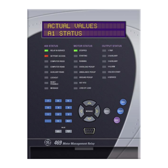
Any trip, alarm, or start block is displayed immediately, automatically overriding the default messages. LED Indicators There are three groups of LED indicators. They are 469 Status, Motor Status, and Output Relays. 806977A1.CDR FIGURE 4–1: 469 LED INDICATORS a) 469 Status LED Indicators •... - Page 72 Output Relay LED Indicators • 1 TRIP: The 1 TRIP relay has operated (energized). • 2 AUXILIARY: The 2 AUXILIARY relay has operated (energized). • 3 AUXILIARY: The 3 AUXILIARY relay has operated (energized). GE Multilin 4–2 http://www.GEindustrial.com/multilin...
-
Page 73: Rs232 Port
This port is intended for connection to a portable PC. Setpoint files may be created at any location and downloaded through this port with the EnerVista 469 Setup software. Local interrogation of setpoints and actual values is also possible. New firmware may also be downloaded to the 469 flash memory through this port. -
Page 74: Setpoint Entry
Memory, as a new setpoint. SWITCH NAME: Stn. Monitor The 469 does not have ‘+’ or ‘–’ keys. Negative numbers may be entered in one of two manners. – Immediately pressing one of the VALUE keys causes the setpoint to scroll through its range including any negative numbers. - Page 75 The following procedure may be used to access and alter setpoints. This specific example refers to entering a valid passcode to allow access to setpoints if the passcode was “469”. Press the MENU key to access the header of each menu, which will be displayed...
-
Page 76: Diagnostic Messages
Diagnostic Messages on page 6–29. Self-Test Warnings The 469 relay performs self test diagnostics at initialization (after power up) and continuously as a background task to ensure the hardware and software is functioning correctly. Self-test warnings indicate either a minor or major problem. -
Page 77: Flash Messages
It can be used while disconnected (i.e. off-line) or connected (i.e. on-line) to a 469 device. In off-line mode, settings files can be created for eventual downloading to the device. In on-line mode, you can communicate with the device in real-time. - Page 78 EnerVista 469 Setup Software Interface Motor Management Relay FIGURE 4–2: Communications using The Front RS232 Port FIGURE 4–3: Communications using Rear RS485 Port GE Multilin 4–8 http://www.GEindustrial.com/multilin...
-
Page 79: Installing The Enervista 469 Setup Software
EnerVista 469 Setup Software Interface Motor Management Relay FIGURE 4–4: Communications using Rear Ethernet Port Installing the EnerVista The following minimum requirements must be met for the EnerVista 469 Setup software to operate on your computer. 469 Setup Software •... - Page 80 Motor Management Relay select “CD” if you do not have a web connection, then click the Add Now button to list software items for the 469. EnerVista Launchpad will obtain the latest installation software from the Web or CD and automatically start the installation process. A status window with a progress bar will be shown during the downloading process.
-
Page 81: Connecting Enervista 469 Setup To The Relay
EnerVista 469 Setup software to the Windows start menu. Click Finish to end the installation. The 469 device will be added to the list of installed IEDs in the EnerVista Launchpad window, as shown below. -
Page 82: Using The Quick Connect Feature
9600, with slave address of 1, no parity, 8 bits, and 1 stop bit. These values cannot be changed. Click the Read Order Code button to connect to the 469 device and upload the order code. If an communications error occurs, ensure that the 469 serial communications values entered in the previous step correspond to the relay setting values. - Page 83 Site List window. The properties of this new site cannot be changed. The 469 Site Device has now been configured via the Quick Connect feature for serial communications. Proceed to Connecting to the Relay on page 4–15 to begin communications.
- Page 84 Slave Address and Modbus Port fields. SERIAL PORTS Click the Read Order Code button to connect to the 469 device and upload the order code. If an communications error occurs, ensure that the 469 Ethernet communications values entered in the previous step correspond to the relay setting values.
- Page 85 Other setpoint and commands windows can be displayed and edited in a similar manner. Actual values windows are also available for display. These windows can be locked, arranged, and resized at will. Refer to the EnerVista 469 Setup Help File for additional information about the using the software. NOTE GE Multilin 4–15...
-
Page 86: Working With Setpoints And Setpoint Files
Working with Setpoints and Setpoint Files Engaging a Device The EnerVista 469 Setup software may be used in on-line mode (relay connected) to directly communicate with a 469 relay. Communicating relays are organized and grouped by communication interfaces and into sites. Sites may contain any number of relays selected from the SR or UR product series. -
Page 87: File Support
In the Setpoint / System Setup dialog box, click on Save to save the values into the 469. Click Yes to accept any changes. Click No, and then Restore to retain previous values and exit. - Page 88 Saving setpoints is also highly recommended before making any setpoint changes or creating new setpoint files. The EnerVista 469 Setup window, setpoint files are accessed in the Settings List control bar window or the Files Window. Use the following procedure to download and save setpoint files to a local PC.
- Page 89 File Name box. Select the file name and path to store the file, or select any displayed file name to update an existing file. All 469 setpoint files should have the extension ‘469’ (for example, ‘motor1.469’). Click Save and OK to complete the process. Once this step is completed, the new file, with a complete path, will be added to the EnerVista 469 Setup software environment.
- Page 90 4–21 for instructions on loading this setpoint file into the 469. f) Printing Setpoints and Actual Values The EnerVista 469 Setup software allows the user to print partial or complete lists of setpoints and actual values. Use the following procedure to print a list of setpoints: Select a previously saved setpoints file in the File pane or establish communications with a 469 device.
- Page 91 The following procedure illustrates how to load setpoints from a file. Before loading a setpoints file, it must first be added to the EnerVista 469 Setup environment as described in Adding Setpoints Files to the Environment on page 4–18.
-
Page 92: Upgrading Relay Firmware
Saving Setpoints To A Before upgrading firmware, it is very important to save the current 469 settings to a File file on your PC. After the firmware has been upgraded, it will be necessary to load this file back into the 469. - Page 93 The 469 will display a message indicating that it is in Upload Mode. While the file is being loaded into the 469, a status box appears showing how much of the new firmware file has been transferred and how much is remaining, as well as the upgrade status.
-
Page 94: Advanced Enervista 469 Setup Features
Waveform Capture The EnerVista 469 Setup software can be used to capture waveforms (or view trace memory) from the 469 relay at the instance of a trip. A maximum of 128 cycles can (Trace Memory) be captured and the trigger point can be adjusted to anywhere within the set cycles. - Page 95 Advanced EnerVista 469 Setup Features Motor Management Relay To view the captured waveforms, click the Launch Viewer button. A detailed Waveform Capture window will appear as shown below: CURSOR LINE POSITION TRIGGER TIME & DATE Indicate the cursor line position VECTOR DISPLAY SELECT Display the time &...
-
Page 96: Phasors
The Waveform Capture window will reappear with the selected graph attributes available for use. Phasors The EnerVista 469 Setup software can be used to view the phasor diagram of three- phase currents and voltages. The phasors are for: phase voltages Va, Vb, and Vc; phase currents Ia, Ib, and Ic. -
Page 97: Trending (Data Logger)
Therefore, if a system condition would cause the current to lead the voltage by 45°, the 469 relay will display such angle as 315° Lag instead of 45° Lead. When the currents and voltages measured by the relay are zero, the angles displayed by the relay and those shown by the EnerVista 469 Setup software are not fixed values. - Page 98 Others: Analog Inputs 1, 2, 3, and 4 Tachometer With EnerVista 469 Setup running and communications established, select the Actual Values > Trending menu item to open the trending window. The fol- lowing window will appear. To prepare for new trending, select Stop to stop the data logger and Reset to clear the screen.
-
Page 99: Event Recorder
FIGURE 4–8: Trending Screen Event Recorder The 469 event recorder can be viewed through the EnerVista 469 Setup software. The event recorder stores generator and system information each time an event occurs (e.g. breaker failure). A maximum of 256 events can be stored, where E256 is the most recent event and E01 is the oldest event. -
Page 100: Modbus User Map
Select Event box. Modbus User Map The EnerVista 469 Setup software provides a means to program the 469 User Map (Modbus addresses 0180h to 01F7h). Refer to GE Publication GEK-106491: 469 Communications Guide for additional information on the User Map. -
Page 101: Viewing Actual Values
Advanced EnerVista 469 Setup Features Motor Management Relay This window allows the desired addresses to be written to User Map locations. The User Map values that correspond to these addresses are then displayed. Viewing Actual Values You can view real-time relay data such as input/output status and measured parameters. - Page 102 Advanced EnerVista 469 Setup Features Motor Management Relay – Power Quantities including Apparent, Real and Reactive Power. – Current and power demand including peak values. – Analog inputs – Vector information. Motor Learned Data: – Learned Acceleration Time – Learned Starting Current –...
-
Page 103: Using Enervista Viewpoint With The 469
Install the EnerVista Viewpoint software from the GE EnerVista CD. Ensure that the 469 device has been properly configured for either serial or Ethernet communications (see previous sections for details). Click the Viewpoint window in EnerVista to log into EnerVista Viewpoint. At this point, you will be required to provide a login and password if you have not already done so. - Page 104 Relay on page 4–11 for details. FIGURE 4–12: Device Setup Screen (Example) Click the Read Order Code button to connect to the 469 device and upload the order code. If an communications error occurs, ensure that communications values entered in the previous step correspond to the relay setting values.
- Page 105 Plug and Play IED dashboard. An icon for the 469 will be shown. FIGURE 4–13: ‘Plug and Play’ Dashboard 12. Click the Dashboard button below the 469 icon to view the device information. We have now successfully accessed our 469 through EnerVista Viewpoint.
- Page 106 Using EnerVista Viewpoint with the 469 Motor Management Relay FIGURE 4–14: EnerVista Plug and Play Screens For additional information on EnerVista viewpoint, please visit the EnerVista website at http://www.enervista.com. GE Multilin 4–36 http://www.GEindustrial.com/multilin...
-
Page 107: Setpoints
5 Setpoints Overview Setpoint Message Map The 469 has a considerable number of programmable setpoints which makes it extremely flexible. The setpoints have been grouped into a number of pages and sub-pages as shown below. Each page of setpoints (e.g. - Page 108 CIRCUIT TRIP OVERLOAD MESSAGE See page 5–50. ALARM MECHANICAL MESSAGE See page 5–50. UNDERCURRENT MESSAGE See page 5–51. CURRENT MESSAGE See page 5–52. UNBALANCE GROUND FAULT MESSAGE See page 5–53. PHASE MESSAGE See page 5–54. DIFFERENTIAL GE Multilin 5–2 http://www.GEindustrial.com/multilin...
- Page 109 S9 VOLTAGE ELEM. OVERVOLTAGE MESSAGE See page 5–66. PHASE MESSAGE See page 5–66. REVERSAL FREQUENCY MESSAGE See page 5–67. END OF PAGE MESSAGE SETPOINTS POWER See page 5–69. S10 POWER ELEMENTS FACTOR REACTIVE MESSAGE See page 5–70. POWER GE Multilin 5–3 http://www.GEindustrial.com/multilin...
- Page 110 MESSAGE See page 5–79. INPUT 2 ANALOG MESSAGE See page 5–79. INPUT 3 ANALOG MESSAGE See page 5–79. INPUT 4 ANALOG INPUT MESSAGE See page 5–81. DIFF 1-2 ANALOG INPUT MESSAGE See page 5–82. DIFF 3-4 GE Multilin 5–4 http://www.GEindustrial.com/multilin...
-
Page 111: Trips, Alarms, And Blocks
The cause of last trip message is updated with the current trip and the 469 display defaults to that message. All trip features are automatically logged and date and time stamped as they occur. -
Page 112: Relay Assignment Practices
469 display defaults to that message. Since it may not be desirable to log all alarms as events, each alarm feature may be programmed to log as an event or not. -
Page 113: S1 469 Setup
Passcodes are also ignored when programming setpoints via the RS485 port. However when programming setpoints using the front RS232 port and the EnerVista 469 Setup software, a passcode is required (if enabled). - Page 114 S1 469 Setup Motor Management Relay Range: 1 to 100% in steps of 1 TRACE MEMORY TRIGGER MESSAGE POSITION: 25% Range:1x64, 2x42, 3x32, 4x35, 5x21, TRACE MEMORY BUFFERS MESSAGE 6x18, 7x16, 8x14, 9x12, 10x11, 8x14 cycles 11x10, 12x9, 13x9, 14x8, 15x8, 16x7 cycles.
-
Page 115: Communications
469 firmware. For RS485 communications, each 469 must have a unique address from 1 to 254. Address 0 is the broadcast address detected by all relays. Addresses do not have to be sequential but no two units can have the same address or errors will occur. - Page 116 BAUD RATE: 125K Enter the dedicated MAC ID and baud rate as per the DeviceNet design. The DeviceNet option is implemented by the 469 relay using the AnyBus-S DeviceNet (HMS) module as a communication adapter. The module is ODVA certified and acts as a server between the relay and the DeviceNet network.
-
Page 117: Real Time Clock
If the RS485 serial communication link is used, then all the relays can keep synchronized time. A new clock time is pre-loaded into the 469 memory via the RS485 port by a remote computer to each relay connected on the communications channel. -
Page 118: Message Scratchpad
S1 469 Setup Motor Management Relay Press ENTER. The message will be PRESS [ENTER] TO ADD DEFAULT MESSAGES displayed for 5 seconds. Press ENTER again while displayed to add the current message to the default message list. If the procedure was followed correctly, the... -
Page 119: Clear Data
Range: No, Yes RESET STARTER MESSAGE INFORMATION: No These commands clear various informative and historical data when the 469 is first applied on a new installation. • RESET MOTOR INFORMATION: Counters for number of motor starts and emergency restarts can be viewed in actual values. The 469 also learns various motor characteristics through motor operation. -
Page 120: S2 System Setup Current Sensing
On solidly grounded systems where fault currents may be quite large, the 469 1A or 5A secondary ground CT input should be used for either zero-sequence or residual ground sensing. If the connection is residual, the Ground CT secondary and primary values should be the same as the phase CT. -
Page 121: Voltage Sensing
1 phase CTs, simply enter the same value here as well. Example 1: Consider a 469 with a 5 A Phase CT secondary and Ground Fault Detection set to Residual and a motor with the following specifications: Motor Nameplate FLA: 87 A; Low Resistance Grounded; Maximum Fault: 400 A The following settings are required: “100”... -
Page 122: Power System
Auxiliary3 RELAYS: Auxiliary2 If enabled, motor starting and stopping is possible via any of the three 469 communication ports. Refer to GE publication GEK-106491: 469 Communications Guide for command formats. When a stop command is issued, the 1 TRIP relay is... -
Page 123: Reduced Voltage
MESSAGE START TIMER: 200 s The 469 can control the transition of a reduced voltage starter from reduced to full voltage. That transition may be based on “Current Only”, “Current and Timer”, or “Current or Timer” (whichever comes first). When the 469 measures the transition of no motor current to some value of motor current, a 'Start' is assumed to be occurring (typically current will rise quickly to a value in excess of FLA, e.g. - Page 124 NOTE contactor and the full voltage contactor. Once transition is initiated, the 469 assumes the motor is still running for at least 2 seconds. This prevents the 469 from recognizing an additional start if motor current goes to zero during an open transition.
-
Page 125: S3 Digital Inputs
(see Passcode on page 5–7). c) Test Switch Once the 469 is in service, it may be tested from time to time as part of a regular maintenance schedule. The relay will have accumulated statistical information relating historically to starter and motor operation. This information includes: last... - Page 126 Shorting terminals D18 and D23 resets any trips or latched alarms provided that the condition that caused the alarm or trip is no longer present. If there is a lockout time the Block Start relay will not reset until the lockout time has expired. GE Multilin 5–20 http://www.GEindustrial.com/multilin...
-
Page 127: Starter Status
STATUS Starter Auxiliary A This input is necessary for all motors. The 469 determines that a motor has stopped when the phase current falls below the level that the relay can measure (5% of CT primary). Monitoring an auxiliary contact from the breaker or contactor prevents the... - Page 128 Remote Trip will cause a trip within 100 ms with the name that has been chosen. Multiple sources may be used to trigger a remote trip by paralleling inputs. REMOTE PUSH-BUTTO N 469 Digital Input Dry contact from other device 808716A1.CDR FIGURE 5–4: Remote Alarm/Trip from Multiple Sources GE Multilin 5–22...
- Page 129 A value of zero for the block time indicates that the feature is always active, when the motor is stopped or running. After the block delay has expired, the digital input will be monitored. If a closure occurs, after the specified delay, an alarm will occur. GE Multilin 5–23 http://www.GEindustrial.com/multilin...
- Page 130 Once Vibration Switch Trip is chosen for a digital input, the setpoints shown follow the assignment message. When the motor is stopped or running, the digital input will be monitored. If a closure occurs, a trip will occur after the specified delay. GE Multilin 5–24 http://www.GEindustrial.com/multilin...
- Page 131 GENERAL COUNTERS DIGITAL actual value. COUNTER To initialize the counter, program the counter value here and then change the S1 469 setpoint to “Yes”. SETUP CLEAR DATA PRESET DIGITAL COUNTER For example, a capacitive proximity probe may be used to sense non-magnetic units that are passing by on a conveyor, glass bottles for instance.
- Page 132 Range: 0.1 to 5000.0 s in steps of 0.1 GENERAL SWITCH A MESSAGE ALARM DELAY: 5.0 s Range: On, Off GENERAL SWITCH A MESSAGE EVENTS: Off Range: Off, Latched, Unlatched GENERAL SWITCH A MESSAGE TRIP: Off GE Multilin 5–26 http://www.GEindustrial.com/multilin...
- Page 133 Setting the to “Simulate Pre-Fault” allows the user to start the INPUT 1(4) FUNCTION Simulate Pre-Fault mode as per the S13 469 TESTING SIMULATION MODE SIMULATION setting via a switch input. This is typically used for relay or system testing.
-
Page 134: S4 Output Relays
Shorting bars in the drawout case ensure that when the 469 is drawn out, no trip or alarm occurs. The the 6 SERVICE relay will however indicate that the 469 has been drawn out. -
Page 135: Force Output Relay
NOT allowed when the selected relay output is FORCE OUTPUT RELAY already active due to trip or alarm condition, when the 469 is in start block condition, or when the 469 is not in service. IMPORTANT NOTE: The forced relay will override any trip or alarm conditions. (i.e. - Page 136 The motor manufacturer should provide a safe stall time or thermal limit curves for any motor they sell. To program the 469 for maximum protection, it is necessary to ask for these items when the motor is out for bid. These thermal limits are intended to be used as guidelines and their definition is not always precise.
-
Page 137: Thermal Model
MESSAGE ALARM EVENTS: Off The primary protective function of the 469 is the thermal model. It consists of five key elements: the overload curve and overload pickup level, the unbalance biasing of the motor current while the motor is running, the motor cooling time constants, and the biasing of the thermal model based on Hot/Cold motor information and measured stator temperature. - Page 138 The 469 overload curve can take one of three formats: Standard, Custom Curve, or Voltage Dependent. Regardless of the selected curve style, thermal memory is...
-
Page 139: Overload Curve Setup
If the motor starting times are well within the safe stall times, it is recommended that the 469 Standard Overload Curve be used. The standard overload curves are a series of 15 curves with a common curve shape based on typical motor thermal limit curves (see the figure and table below). - Page 140 S5 Thermal Model Motor Management Relay Table 5–1: 469 Standard Overload Curve Multipliers PICKUP STANDARD CURVE MULTIPLIERS (× FLA) × 1 × 2 × 3 × 4 × 5 × 6 × 7 × 8 × 9 × 10 × 11 ×...
- Page 141 Range: 0.5 to 99999.9 s in steps of 0.1 TIME TO TRIP AT MESSAGE 5.50 x FLA: 12.0 s Range: 0.5 to 99999.9 s in steps of 0.1 TIME TO TRIP AT MESSAGE 6.00 x FLA: 10.0 s GE Multilin 5–35 http://www.GEindustrial.com/multilin...
- Page 142 The distinct parts of the thermal limit curves now become more critical. For these conditions, it is recommended that the 469 custom curve thermal model be used. The custom overload curve feature allows the user to program their own curve by entering trip times for 30 pre-determined current levels.
- Page 143 Motor Management Relay GE Multilin TYPICAL CUSTOM CURVE 6500 HP, 13800 VOLT INDUCED DRAFT FAN MOTOR 10000 PROGRAMMED 469 CUSTOM CURVE RUNNING SAFETIME (STATOR LIMIT) ACCELERATION SAFETIME (ROTOR LIMIT) MOTOR CURRENT at 100% VOLTAGE 1000 MOTOR CURRENT at 80% VOLTAGE MULTIPLE OF FULL LOAD CURRENT SETPOINT 806803A6.CDR...
- Page 144 Range: 0.5 to 99999.9 s in steps of 0.1 TIME TO TRIP AT MESSAGE 5.50 x FLA: 12.0 s Range: 0.5 to 99999.9 s in steps of 0.1 TIME TO TRIP AT MESSAGE 6.00 x FLA: 10.0 s GE Multilin 5–38 http://www.GEindustrial.com/multilin...
- Page 145 This method of protection inherently accounts for the change in motor speed as an impedance relay would. The change in impedance is reflected by motor terminal voltage and line current. For any given speed at any given line voltage, there is only one value of line current. GE Multilin 5–39 http://www.GEindustrial.com/multilin...
- Page 146 S5 Thermal Model Motor Management Relay GE Multilin HIGH INERTIA LOAD OVERLOAD CURVES 8800 HP, 13.2 kV, REACTOR COOLANT PUMP 1000 1- Running Overload Thermal Limit 2- Acceleration Thermal Limit at 80%V 3- Acceleration Thermal Limit at 100%V 4- Locked Rotor Thermal Limit...
- Page 147 S5 Thermal Model Motor Management Relay GE Multilin HIGH INERTIA LOAD OVERLOAD CURVES 8800 HP, 13.2 kV, REACTOR COOLANT PUMP 1000 469 Custom Curve MULTIPLES OF FULL LOAD AMPS 806822A4.CDR FIGURE 5–9: Voltage Dependent Overload Curve (Custom Curve) GE Multilin 5–41...
- Page 148 S5 Thermal Model Motor Management Relay GE Multilin HIGH INERTIA LOAD OVERLOAD CURVES 8800 HP, 13.2 kV, REACTOR COOLANT PUMP 1000 Acceleration intersect at 80%V Acceleration Intersect at 100%V MULTIPLES OF FULL LOAD AMPS 806823A4.CDR FIGURE 5–10: Voltage Dependent Overload Curves (Acceleration Curves) GE Multilin 5–42...
- Page 149 The 469 takes the information provided and create protection curves for any voltage between the minimum and 100%. For values above the voltage in question, the 469 extrapolates the safe stall protection curve to 110% voltage. This current level is calculated by taking the locked rotor current at 100% voltage and multiplying by 1.10.
- Page 150 Motor Management Relay The following two figures illustrate the resultant overload protection curves for 80% and 100% line voltage, respectively. For voltages in between, the 469 will shift the acceleration curve linearly and constantly based on measured line voltage during a motor start.
- Page 151 The 469 measures the ratio of negative to positive-sequence current. The thermal model may be biased to reflect the additional heating that is caused by negative sequence current when the motor is running.
- Page 152 0.167, voltage unbalances of 1, 2, 3, 4, and 5% equal current unbalances of 6, 12, 18, 24, and 30% respectively. Based on this assumption, the GE Multilin curve illustrates the motor derating for different values of k entered for the setpoint.
- Page 153 Hot/Cold Safe Stall Ratio The motor manufacturer may provide thermal limit information for a hot/cold motor. The 469 thermal model adapts for these conditions if the HOT/COLD SAFE STALL RATIO setpoint is programmed. This setpoint value dictates the level of thermal capacity...
- Page 154 Motor Management Relay h) RTD Bias The 469 thermal replica operates as a complete and independent model. However, the thermal overload curves are based solely on measured current, assuming normal 40°C ambient and normal motor cooling. If the ambient temperature is unusually high, or motor cooling is blocked, the motor temperature will increase.
-
Page 155: S6 Current Elements
This allows the motor to start without nuisance tripping. The overreach filter removes the DC component from the asymmetrical current present at the moment of fault. This eliminates overreach; however, the response time slows slightly (10 to 15 ms) but remains within specification. GE Multilin 5–49 http://www.GEindustrial.com/multilin... -
Page 156: Overload Alarm
MECHANICAL JAM PICKUP normal operation, but lower than the motor stall level. Normally the delay is set to the minimum time delay or set so that no nuisance trips occur due to momentary load fluctuations. GE Multilin 5–50 http://www.GEindustrial.com/multilin... -
Page 157: Undercurrent
“0.75”. If the pump is always started loaded, the PICKUP BLOCK UNDERCURRENT setpoint should be disabled (programmed as “0”). FROM START is typically set as quick UNDERCURRENT ALARM DELAY UNDERCURRENT TRIP DELAY as possible, i.e. 1 second. GE Multilin 5–51 http://www.GEindustrial.com/multilin... -
Page 158: Current Unbalance
Range: 1 to 60 s in steps of 1 CURRENT UNBALANCE MESSAGE TRIP DELAY: 1 s For the 469 relay, unbalance is defined as the ratio of negative-sequence to positive-sequence current, I , if the motor is operating at a load (I ) greater than FLA. -
Page 159: Ground Fault
Various situations (e.g. contactor bounce) may cause transient ground currents during motor starting that may exceed the Ground Fault pickup levels for a very short period of time. The Ground Fault time delays are adjustable in 10 ms GE Multilin 5–53 http://www.GEindustrial.com/multilin... -
Page 160: Phase Differential
This momentary DC component will cause each of the phase CTs to react differently and the net current into the ground input of the 469 will not be negligible. A 20 ms block of the ground fault elements when the motor starts enables the 469 to ride through this momentary ground current signal. -
Page 161: S7 Motor Starting Acceleration Timer
Some motor soft-starters allow current to ramp up slowly while others limit current to less than FLA throughout the start. Since the 469 is a generic motor relay, it cannot differentiate between a motor with a slow ramp up time and one that has completed a start and gone into overload. -
Page 162: Jogging Block
• Max. Starts/Hour Permissible: A motor start is assumed to be occurring when the 469 measures the transition of no motor current to some value of motor current. At this point, one of the Starts/Hour timers is loaded with 60 minutes. -
Page 163: Restart Block
The motor has now become a generator and applying supply voltage out of phase may result in catastrophic failure. The Restart Block feature is strictly a timer. The 469 does not sense rotor rotation. NOTE... - Page 164 164.76 269.91 224.92 15.61 168.47 280.77 233.97 16.00 172.46 291.96 243.30 16.39 175.84 303.46 252.88 16.78 179.51 315.31 262.76 17.17 183.17 327.54 272.94 17.56 186.82 340.14 283.45 17.95 190.45 353.14 294.28 18.34 194.08 366.53 305.44 18.73 GE Multilin 5–58 http://www.GEindustrial.com/multilin...
-
Page 165: Rtds 1 To 6
If enabled, a second RTD must also exceed the trip temperature of the RTD being checked before a trip will be issued. If the RTD is chosen to vote with itself, the voting feature is disabled. Each RTD name may be changed if desired. GE Multilin 5–59 http://www.GEindustrial.com/multilin... -
Page 166: Rtds 7 To 10
If enabled, a second RTD must also exceed the trip temperature of the RTD being checked before a trip will be issued. If the RTD is chosen to vote with itself, the voting feature is disabled. Each RTD name may be changed if desired. GE Multilin 5–60 http://www.GEindustrial.com/multilin... -
Page 167: Rtd 11
RTD malfunction. If enabled, a second RTD must also exceed the trip temperature of the RTD being checked before a trip will be issued. If the RTD is chosen to vote with itself, the voting feature is disabled. The RTD name may be changed if desired. GE Multilin 5–61 http://www.GEindustrial.com/multilin... -
Page 168: Rtd 12
RTD malfunction. If enabled, a second RTD must also exceed the trip temperature of the RTD being checked before a trip will be issued. If the RTD is chosen to vote with itself, the voting feature is disabled. The RTD name may be changed if desired. GE Multilin 5–62 http://www.GEindustrial.com/multilin... -
Page 169: Open Rtd Sensor
MESSAGE ALARM EVENTS: Off The 469 has an Open RTD Sensor alarm. This alarm will look at all RTDs that have either an alarm or trip programmed and determine if an RTD connection has been broken. Any RTDs that do not have a trip or alarm associated with them will be ignored for this feature. -
Page 170: S9 Voltage Elements
On the other hand, if undervoltage trip is enabled, and the UNDERVOLTAGE TRIP is set for “1-Phase”, a trip will occur once the magnitude of either Vab, Vbc, or MODE Vca falls below the pickup level while running or starting for a period of time GE Multilin 5–64 http://www.GEindustrial.com/multilin... - Page 171 “3-Phase”, when the setpoint UNDERVOLTAGE TRIP MODE S2 SYSTEM SETUP is set to “On”. The relay assumes a VOLTAGE SENSING ENABLE SINGLE VT OPERATION balanced three phase system when fed from a single VT. NOTE GE Multilin 5–65 http://www.GEindustrial.com/multilin...
-
Page 172: Overvoltage
Aux2 & Aux3, Trip & Auxiliary3 Trip The 469 can detect the phase rotation of the three phase voltage. If the Phase Reversal feature is turned on when all 3 phase voltages are greater than 50% motor nameplate voltage, and the phase rotation of the three phase voltages is not the same as the setpoint, a trip and block start will occur in 500 to 700 ms. -
Page 173: Frequency
This feature may be useful for load shedding applications on large motors. It could also be used to load shed an entire feeder if the trip was assigned to an upstream breaker. GE Multilin 5–67 http://www.GEindustrial.com/multilin... -
Page 174: S10 Power Elements
Power Measurement By convention, an induction motor consumes Watts and vars. This condition is displayed on the 469 as +Watts and +vars. A synchronous motor can consume Conventions Watts and vars or consume Watts and generate vars. These conditions are displayed on the 469 as +Watts, +vars, and +Watts, –vars respectively (see the figure... -
Page 175: Power Factor
MESSAGE DELAY: 1.0 s If the 469 is applied on a synchronous motor, it is desirable not to trip or alarm on power factor until the field has been applied. Therefore, this feature can be blocked until the motor comes up to speed and the field is applied. From that point forward, the power factor trip and alarm elements will be active. -
Page 176: Reactive Power
MESSAGE DELAY: 1.0 s If the 469 is applied on a synchronous motor, it is desirable not to trip or alarm on kvar until the field has been applied. Therefore, this feature can be blocked until the motor comes up to speed and the field is applied. From that point forward, the kvar trip and alarm elements will be active. -
Page 177: Underpower
Power is a more accurate representation of loading and may be used for more sensitive detection of load loss or pump cavitation. This may be especially useful for detecting process related problems. GE Multilin 5–71 http://www.GEindustrial.com/multilin... -
Page 178: Reverse Power
The default unit for torque is the SI unit of Newton-meter (Nm). The torque unit is selectable to either Newton-meter or foot-pound. 1 Nm = 0.738 ft·lb. NOTE GE Multilin 5–72 http://www.GEindustrial.com/multilin... -
Page 179: Overtorque
A breakdown of trips by type may be found on . If a trend is detected, it would warrant further MAINTENANCE\TRIP COUNTERS investigation. GE Multilin 5–73 http://www.GEindustrial.com/multilin... -
Page 180: Starter Failure
“Latched” or “Unlatched”, then the Starter STARTER FAILURE ALARM Status input and motor current are monitored when the 469 initiates a trip. If the starter status contacts do not change state or motor current does not drop to zero after the programmed time delay, an alarm occurs. -
Page 181: Demand
MESSAGE ALARM EVENTS: Off The 469 measures motor demand for several parameters (current, kW, kvar, and kVA). These values may be of interest for energy management programs where processes may be altered or scheduled to reduce overall demand on a feeder. -
Page 182: Pulse Output
1 second. This feature should be programmed such that no more than one pulse per second will be required or the pulsing will lag behind the interval activation. NOTE GE Multilin 5–76 http://www.GEindustrial.com/multilin... -
Page 183: S12 Analog Inputs/Outputs
MESSAGE MAX: 1000 kW The 469 has four analog output channels (4 to 20 mA or 0 to 1 mA as ordered). Each channel may be individually configured to represent a number of different measured parameters as shown in the table below. The minimum value programmed represents the 4 mA output. - Page 184 –50000 to +50000 +50000 Tachometer 100 to 7200 RPM 3500 3700 MWhrs 0.000 to 999999.999 MWhrs 0.001 50.000 100.000 Analog In Diff 1-2 –50000 to +50000 Analog In Diff 3-4 –50000 to +50000 Torque 0 to 999999.9 GE Multilin 5–78 http://www.GEindustrial.com/multilin...
-
Page 185: Analog Inputs 1 To 4
0, the feature will be disabled when the motor is stopped and also from the time a start is detected until the time entered expires. Once the input is setup, both the trip and alarm features may be configured. In addition to programming a level GE Multilin 5–79 http://www.GEindustrial.com/multilin... - Page 186 Program as “0” minutes. Set the alarm for a BLOCK ANALOG INPUT 1(4) FROM START reasonable level slightly higher than the normal vibration level. Program a delay of “3 s” and a pickup value of “Over”. GE Multilin 5–80 http://www.GEindustrial.com/multilin...
- Page 187 For example, two motors on a dual motor drive are each protected a 469. The motors should be at the same power level (kW). Connect the analog outputs (programmed for kW) from both relays to the analog inputs of one relay.
-
Page 188: Analog Input Diff 1-2
(“3>4”) or vice versa (“4>3”) or as absolute difference (“3<>4”). Note that the compared analog inputs must be programmed with the same unit type prior to using this feature. GE Multilin 5–82 http://www.GEindustrial.com/multilin... -
Page 189: S13 469 Testing Simulation Mode
If however, the 469 has been installed and will remain installed on a specific motor, it might be desirable to short the 469 Test input (C3 and C4) to prevent all of this data from being corrupted or updated. In any case, when in simulation mode, the 469 In Service LED (indicator) will flash, indicating that the 469 is not in protection mode. -
Page 190: Pre-Fault Setup
Range: 0 to 100% in steps of 1 PRE-FAULT ANALOG MESSAGE INPUT 4: 0% The values entered under Pre-Fault Values will be substituted for the measured values in the 469 when the simulation mode is “Simulate Pre-Fault”. GE Multilin 5–84 http://www.GEindustrial.com/multilin... -
Page 191: Fault Setup
Range: 0 to 100% in steps of 1 FAULT ANALOG MESSAGE INPUT 4: 0% The values entered under Fault Values will be substituted for the measured values in the 469 when the simulation mode is “Simulate Fault”. GE Multilin 5–85 http://www.GEindustrial.com/multilin... -
Page 192: Test Output Relays
FORCE OPERATION OF RELAYS automatically become disabled and the output relays will revert back to their normal states. If any relay is forced, the 469 In Service LED will flash, indicating that the 469 is not in protection mode. Test Analog Outputs... -
Page 193: Comm Port Monitor
During the course of troubleshooting communications problems, it can be very useful to see the data that is first being transmitted to the 469 from some master device, and then see the data that the 469 transmits back to that master device. -
Page 194: S14 Two-Speed Motor
Contact closure signifies that the motor is in Speed 2; if the input is open, it signifies that the motor is in Speed 1. This allows the 469 to determine which setpoints should be active at any given point in time. Two-speed motor protection is... - Page 195 Range: 0.5 to 99999.9 in steps of 0.1 SPEED2 TRIP AT MESSAGE 20.0 x FLA: 5.6 s Refer to Custom Overload Curve on page 5–35 for additional details on the custom overload curves available for Speed2. GE Multilin 5–89 http://www.GEindustrial.com/multilin...
- Page 196 5.00 x FLA: 14.6 s Range: 0.5 to 99999.9 in steps of 0.1 SPEED2 TRIP AT MESSAGE 5.50 x FLA: 12.0 s Range: 0.5 to 99999.9 in steps of 0.1 SPEED2 TRIP AT MESSAGE 6.00 x FLA: 10.0 s GE Multilin 5–90 http://www.GEindustrial.com/multilin...
- Page 197 SPEED2 ISTALL @ 100% SPEED2 ACL INTERSECT MESSAGE VLINE – 0.01 in steps of 0.01 @100% Vline: 5.00xFLA Refer to Voltage Dependent Overload Curves on page 5–38 for additional details on the custom overload curves available for Speed2. GE Multilin 5–91 http://www.GEindustrial.com/multilin...
-
Page 198: Speed2 Undercurrent
Speed 1 to Speed 2. Also, while the motor is running, the 469 will ignore Mechanical Jam protection during the acceleration from Speed 1 to Speed 2 until the motor current has dropped below Speed 2 FLA ×... -
Page 199: Actual Values
END OF PAGE MESSAGE ACTUAL VALUES CURRENT See page 6–9. A2 METERING DATA METERING TEMPERATURE MESSAGE See page 6–10. VOLTAGE MESSAGE See page 6–10. METERING SPEED MESSAGE See page 6–11. POWER MESSAGE See page 6–11. METERING GE Multilin 6–1 http://www.GEindustrial.com/multilin... - Page 200 See page 6–27. A5 EVENT RECORD <Cause> ↓ EVENT MESSAGE See page 6–27. END OF PAGE MESSAGE ACTUAL VALUES 469 MODEL See page 6–29. A6 PRODUCT INFO. INFORMATION CALIBRATION MESSAGE See page 6–29. INFORMATION END OF PAGE MESSAGE GE Multilin 6–2...
-
Page 201: Description
Value mode. Actual values may be accessed via one of the following methods: The front panel, using the keys and display. The front program port and a portable computer running the EnerVista 469 Setup software supplied with the relay. The rear RS485 port and a PLC/SCADA system running user-written software. -
Page 202: A1 Status Network Status
Low Speed These messages describe the motor status at any given point in time. If the motor has been tripped and the 469 has not yet been reset, the value will MOTOR STATUS be “Tripped”. The... - Page 203 MESSAGE Analog Input 4 is “Disabled”. PreTrip: 0 Units Immediately prior to issuing a trip, the 469 takes a snapshot of motor parameters and stores them as pre-trip values that allow for troubleshooting after the trip occurs. The message is updated with the current trip and the CAUSE OF LAST TRIP screen defaults to that message.
-
Page 204: Alarm Status
Range: 0.00 to 0.99 Lead or Lag, 0.00, POWER FACTOR MESSAGE 1.00 ALARM PF: 0.00 Range: –50000 to +50000 kvar REACTIVE POWER MESSAGE ALARM: +2000 kvar Range: –50000 to +50000 kW UNDERPOWER MESSAGE ALARM: 200 kW GE Multilin 6–6 http://www.GEindustrial.com/multilin... - Page 205 The status is “Active” if the condition that caused the alarm is still present. If the 469 chassis is only partially engaged with the case, the ALARM, 469 NOT service alarm appears after 1 second. Secure the chassis handle INSERTED PROPERLY to ensure that all contacts mate properly.
-
Page 206: Start Blocks
Note: Seen only if Phase CT Primary WARNING MESSAGE or Motor FLA not programmed 469 NOT PROGRAMMED Any active blocking functions may be viewed here. The WARNING 469 NOT message is seen only if the Phase CT Primary or Motor FLA setpoints PROGRAMMED have not been programmed. -
Page 207: Real Time Clock
Range: 01 to 12 / 01 to 31 / 1995 to 2094 REAL TIME DATE: 01/01/1994 CLOCK TIME: 12:00:00 The time and date from the 469 real time clock may be viewed here. A2 Metering Data Current Metering PATH: ACTUAL VALUES A2 METERING DATA... -
Page 208: Temperature
Range: 0 to 20000 V. Seen only if VT AVERAGE PHASE MESSAGE Connection is set as Wye VOLTAGE: 0 Volts Range: 0.00, 20.00 to 120.00 Hz SYSTEM FREQUENCY: MESSAGE 0.00 Hz Measured voltage parameters will be displayed here. GE Multilin 6–10 http://www.GEindustrial.com/multilin... -
Page 209: Speed
Real Power (hp) is converted directly from Real Power (kW). This display- only value is not used for protection functions. This message will not display more than 65535 hp regardless of the actual kW that are being NOTE metered. GE Multilin 6–11 http://www.GEindustrial.com/multilin... -
Page 210: Demand Metering
“None”. Peak Demand information is VT RATIO cleared with the setpoint. S1 469 SETUP CLEAR DATA CLEAR PEAK DEMAND DATA Demand is shown only for positive real and positive reactive power. Analog Inputs... -
Page 211: Phasors
WARNING The EnerVista 469 Setup software is a useful tool to view the vectors seen by the relay in graphical format. The same information described above is displayed by the EnerVista 469 Setup software as follows: FIGURE 6–1: Vector display in EnerVista 469 Setup... - Page 212 Load FIGURE 6–2: Flow Direction of Signed Values for Watts and Vars All phasors calculated by 469 relays are rotating phasors that maintain the correct phase angle relationships with each other at all times. For display purposes, all phasor angles in a given relay are referred to phase Van or...
- Page 213 30 degrees. FIGURE 6–4: Current Lagging Voltage by 30° Display The phasors shown by the relay and the EnerVista 469 Setup software are a clear representation of the relationship between the system quantities as seen by the relay.
- Page 214 The voltage measured between terminals H1 (V ) and G1 (V ) is displayed by the relay as “Vc Phasor” and “Vcb” by the EnerVista 469 Setup software. In this case, Vc Phasor is equal to the system quantity Vcb or –Vbc. •...
- Page 215 Ia PHASOR : “100.0% at 168° Lag” Ib PHASOR : “100.0% at 288° Lag” Ic PHASOR The EnerVista 469 Setup software displays the following screen for A2 METERING DATA values: PHASORS Pressing the “View” button displays the following screen: The following phasor diagram illustrates the vector diagram of our example. By definition, power factor is the cosine of the angle between the phase to neutral voltages and the corresponding phase current.
- Page 216 + (=kW) 0.3 pf 0.7 pf 1.00 pf 0.7 pf 0.3 pf Rotation (72.5°) lag (45°) lag (0°) lag (45°) lead (72.5°) lead 0° 0° 0° ---- ---- ---- ---- ---- kVAR – – + (=kW) GE Multilin 6–18 http://www.GEindustrial.com/multilin...
- Page 217 × VC 806562A1.CDR FIGURE 6–8: Wye VT Connection The quantities displayed by the relay and the EnerVista 469 Setup software are straightforward and follow the phasor diagram shown below. Note that all the angles shown are negative or lagging angles.
- Page 218 In this example, 18.2° is the angle between Van and Ia, Vbn and Ib, and Vcn and Ic. The phase-to-phase quantities are not shown in the A2 METERING menu and the EnerVista 469 Setup software. However, they are DATA PHASORS shown on the following figure.
- Page 219 – + (= kW) 0.3 pf 0.7 pf 1.00 pf 0.7 pf 0.3 pf rotation (72.5°) lag (45°) lag (0°) lag (45°) lead (72.5°) lead 0° lag 0° lag 0° lag kVAR – – + (=kW) GE Multilin 6–21 http://www.GEindustrial.com/multilin...
-
Page 220: A3 Learned Data
Range: 0.00 to 20.00 AVERAGE AVERAGE MOTOR LOAD MOTOR LOAD LEARNED: 0.00 x FLA The 469 can learn the average motor load over a period of time. This time is specified by the S1 469 SETUP PREFERENCES AVERAGE MOTOR LOAD CALC. PERIOD setpoint (default 15 minutes). -
Page 221: Rtd Maximums
MESSAGE MAX. TEMP.: 40°C Range: –50 to 250°C RTD #12 MESSAGE MAX. TEMP.: 40°C The 469 will learn the maximum temperature for each RTD. This information can be cleared using the setpoint. S1 469 SETUP CLEAR DATA CLEAR RTD MAXIMUMS... -
Page 222: Analog Input Min/Max
ANALOG I/P 4 MESSAGE MAX: 0 Units The 469 will learn the minimum and maximum values of the analog inputs since they were last cleared. This information can be cleared with the S1 469 SETUP setpoint. When the data is cleared, the... - Page 223 Range: 0 to 50000 ANALOG I/P 3 MESSAGE TRIPS: 0 Range: 0 to 50000 ANALOG I/P 4 MESSAGE TRIPS: 0 Range: 0 to 50000 ANALOG 1-2 MESSAGE TRIPS: 0 Range: 0 to 50000 ANALOG 3-4 MESSAGE TRIPS: 0 GE Multilin 6–25 http://www.GEindustrial.com/multilin...
-
Page 224: General Counters
MESSAGE 0 min One of the 469 timers accumulates the total running time for the Motor. This may be useful for scheduling routine maintenance. When this timer exceeds 100000, it will reset to 0. This timer can be cleared using the... -
Page 225: A5 Event Recorder
Range: –50000 to 50000. Not seen if ANALOG I/P 1 MESSAGE Analog Input 1 is Disabled. EVENT01: 0 Units Range: –50000 to 50000. Not seen if ANALOG I/P 2 MESSAGE Analog Input 2 is Disabled. EVENT01: 0 Units GE Multilin 6–27 http://www.GEindustrial.com/multilin... - Page 226 An event description is stored along with a time and date stamp for troubleshooting purposes. Events include all trips, any alarm optionally (except Service Alarm, and 469 Not Inserted Alarm, which always records as events), loss of control power, application of control power, emergency restarts, and motor starts when a blocking function is active.
-
Page 227: A6 Product Info
MESSAGE number. All of the 469 model information may be viewed here when the unit is powered up. In the event of a product software upgrade or service question, the information shown here should be jotted down prior to any inquiry. - Page 228 Setpoint messages are being viewed and there are no trips, alarms, or blocks, the Message LED (indicator) will be on solid. From any point in the message structure, pressing the NEXT key will cause the 469 to revert back to the normal default messages. When normal default messages are being displayed, pressing NEXT displays the next default message immediately.
-
Page 229: Flash Messages
Flash messages are warning, error, or general information messages that are temporarily displayed in response to certain key presses. These messages are intended to assist with navigation of the 469 messages by explaining what has happened or by prompting the user to perform certain actions. - Page 230 OUT OF RANGE! ENTER: #### - ##### by #: If an entered setpoint value that is outside of the acceptable range of values, the 469 displays this message, substituting the proper values for that setpoint. An appropriate value may then be entered.
- Page 231 • ROUNDED SETPOINT HAS BEEN STORED: A setpoint value entered with the numeric keypad may be between valid setpoint values. The 469 detects this condition and stores a value that has been rounded to the nearest valid setpoint value. To find the valid range and step for a given setpoint, simply press HELP while the setpoint is being displayed.
- Page 232 Diagnostics Motor Management Relay GE Multilin 6–34 http://www.GEindustrial.com/multilin...
- Page 233 Since the 469 is packaged in a drawout case, a demo case (metal carry case in which an 469 may be mounted) may be useful for creating a portable test set. Testing of the relay during commissioning using a primary injection test set will ensure that CTs and wiring are correct and complete.
-
Page 234: Overview
Overview Motor Management Relay FIGURE 7–1: Secondary Injection Test Setup GE Multilin 7–2 http://www.GEindustrial.com/multilin... -
Page 235: Hardware Functional Testing
Motor Management Relay Hardware Functional Testing Phase Current The 469 specification for phase current accuracy is ±0.5% of 2 × CT when the injected current is less than 2 × CT. Perform the steps below to verify accuracy. Accuracy Test Alter the following setpoint: “1000 A”... -
Page 236: Ge Multilin 50:0.025 Ground Accuracy Test
Measured values should be ±0.125 A. Inject the values shown in the table below either as primary values into a GE Multilin 50:0.025 Core Balance CT or as sec- ondary values that simulate the core balance CT. Verify accuracy of the mea- sured values. - Page 237 SELECT ONE: ____(°C) ____(°F) 10 Ω COPPER °Celsius °Fahrenheit 7.10 Ω –50°C –58°F 9.04 Ω 0°C 32°F 10.97 Ω 50°C 122°F 12.90 Ω 100°C 212°F 14.83 Ω 150°C 302°F 16.78 Ω 200°C 392°F 18.73 Ω 250°C 482°F GE Multilin 7–5 http://www.GEindustrial.com/multilin...
-
Page 238: Digital Inputs And Trip Coil Supervision
TRIP COIL SUPERVISION No Coil Coil Analog Inputs and The 469 specification for analog input and analog output accuracy is ±1% of full scale. Perform the steps below to verify accuracy. Verify the Analog Input +24 V DC Outputs with a voltmeter. -
Page 239: Output Relays
✔ All Relays ✔ ✔ ✔ ✔ ✔ ✔ No Relays ✔ ✔ ✔ ✔ ✔ ✔ The 6 SERVICE relay is failsafe or energized normally. Operating the 6 SERVICE relay causes it to de-energize. NOTE GE Multilin 7–7 http://www.GEindustrial.com/multilin... -
Page 240: Additional Functional Testing
Additional Functional Testing Overload Curve Test The 469 specification for overload curve timing accuracy is ±100 ms or ±2% of time to trip. Pickup accuracy is as per the current inputs (±0.5% of 2 × CT when the injected current is less than 2 × CT and ±1% of 20 × CT when the injected current is ≥... -
Page 241: Unbalance Test
Vc = 120 V ∠168° Vc = 120 V ∠168° Unbalance Test The 469 measures the ratio of negative sequence current (I ) to positive sequence current (I ). This value as a percent is used as the unbalance level when motor load exceeds FLA. -
Page 242: Voltage Phase Reversal Test
Vc = 120 V ∠120° Short Circuit Test The 469 specification for short circuit timing is +50 ms. The pickup accuracy is as per the phase current inputs. Perform the steps below to verify the performance of the short circuit element. - Page 243 NEXT after each trip. INJECTED CURRENT EXPECTED TIME MEASURED TIME TO TRIP TO TRIP 5 A UNIT 1 A UNIT 30 A < 50 ms 40 A < 50 ms 50 A 10 A < 50 ms GE Multilin 7–11 http://www.GEindustrial.com/multilin...
- Page 244 Additional Functional Testing Motor Management Relay GE Multilin 7–12 http://www.GEindustrial.com/multilin...
-
Page 245: Appendix
Note that there is only one ground connection as shown. If two ground connections are made, a parallel path for current has been created. :COM :COM :COM 808700A1.CDR GE Multilin 8–1 http://www.GEindustrial.com/multilin... -
Page 246: Cool Time Constants
(rotor and stator) without impeding the normal and expected operating conditions of the motor. The 469 thermal model provides integrated rotor and stator heating protection. If supplied with the motor, the cooling time constants recommended by the manufacturer should be used. -
Page 247: Example
5 hours. • Since the rotor cools faster when the motor is running, a reasonable setting for the running cool time constant might be half the stopped cool time constant or 150 minutes. GE Multilin 8–3 http://www.GEindustrial.com/multilin... -
Page 248: Current Transformers
Motor Management Relay Current Transformers Ground Fault CTs for CTs that are specially designed to match the ground fault input of GE Multilin motor protection relays should be used to ensure correct performance. These CTs have a 50:0.025 A CT 50:0.025A (2000:1 ratio) and can sense low leakage currents over the relay setting... -
Page 249: Ground Fault Cts For 5 A Secondary Ct
For low resistance or solidly grounded systems, a 5 A secondary CT should be used. 5 A Secondary CT Two sizes are available with 5½” or 13” × 16” windows. Various Primary amp CTs can be chosen (50 to 250). GCT5 GCT16 DIMENSIONS DIMENSIONS 808709A1.CDR GE Multilin 8–5 http://www.GEindustrial.com/multilin... -
Page 250: Phase Cts
Current transformers in most common ratios from 50:5 to 1000:5 are available for use as phase current inputs with motor protection relays. These come with mounting hardware and are also available with 1 A secondaries. Voltage class: 600 V BIL 10 kV. 808712A1.CDR GE Multilin 8–6 http://www.GEindustrial.com/multilin... -
Page 251: Eu Declaration Of Conformity
48710 Zamudio, Spain Telephone: 34-94-4858835 Fax: 34-94-4858838 Type of Equipment: Protection and Control Relay Model Number: 469 First Year of Manufacture: 1998 I the undersigned, hereby declare that the equipment specified above conforms to the above Directives and Standards Full Name: John Saunders... -
Page 252: Change Notes
24 months from date of shipment from factory. In the event of a failure covered by warranty, GE Multilin will undertake to repair or replace the device providing the warrantor determined that it is defective and it is returned with all transportation charges prepaid to an authorized service centre or the factory. - Page 253 AVERAGE PHASE CURRENT ........6-9 trip counter ............6-25 ACCESS SWITCH ..........5-19 ACCESSORIES ............2-4 ACTUAL VALUES A1 STATUS ............6-4 A2 METERED DATA ..........6-9 BAUD RATE A3 LEARNED DATA ..........6-22 setpoints ............. 5-9 5-10 GE Multilin http://www.GEindustrial.com/multilin...
- Page 254 ......5-41 5-42 EMERGENCY RESTART ......5-13 5-20 6-26 CUTOUT PANELS ............. 3-3 ENERVISTA VIEWPOINT WITH THE 469 ...... 4-33 ENTERING TEXT ............4-4 ENVIRONMENTAL SPECIFICATIONS ......2-10 ESTIMATED TRIP TIME ON OVERLOAD ......6-4 ETHERNET actual values ............6-3 setpoints .............5-9...
- Page 255 .............3-1 FEATURES .............. 2-2 putting the relay in Ready state ......1-28 FIRMWARE setpoints ............5-13 upgrading via EnerVista 469 setup software ..... 4-22 INTENTIONAL S/C TRIP DELAY ......... 5-49 FLA ............. 5-14 5-15 FLASH MESSAGES ........6-31 6-32 6-33 FLOW ..............
- Page 256 ............2-6 POWER SYSTEM ............. 5-16 OVERFREQUENCY PRE-FAULT SETUP ..........5-84 setpoints ............5-67 PRE-FAULT SIMULATION ......... 5-27 specifications ............2-6 PRE-FAULT TO FAULT SIMULATION ......5-27 OVERLOAD ALARM ..........5-50 PREFERENCES ............5-7 OVERLOAD CURVE MULTIPLIERS ....... 5-34 GE Multilin http://www.GEindustrial.com/multilin...
- Page 257 REMOTE SWITCH ............. 2-7 S13 469 TESTING ..........5-83 REMOTE TRIP ............5-22 S14 TWO-SPEED MOTOR ......... 5-88 REMOVING THE 469 FROM THE CASE ......3-4 S2 SYSTEM SETUP RESET ..............5-5 setpoints ............5-14 RESET MOTOR INFORMATION ........5-13 settings example ..........
- Page 258 SETPOINT MESSAGE MAP ......... 5-1 specifications ............2-8 SETPOINTS TACHOMETER TRIPS ..........6-24 changing ............. 1-6 TC USED MARGIN ..........5-55 entering with EnerVista 469 setup software ....4-16 TEMPERATURE ............6-10 loading from a file ..........4-21 TEMPERATURE DISPLAY ..........5-8 messages ............5-1 TERMINALS numerical ............
- Page 259 PHASE REVERSAL VOLTAGE PHASE REVERSAL TEST ......7-10 VOLTAGE SENSING setpoints ............5-15 VOLTAGE TRANSFORMER see VTs VOLTAGE TRANSFORMER RATIO ....... 5-15 VT CONNECTION TYPE ..........5-15 VT RATIO ............. 5-15 3-phase open delta ..........6-18 GE Multilin http://www.GEindustrial.com/multilin...
- Page 260 Motor Management Relay GE Multilin viii http://www.GEindustrial.com/multilin...