Advertisement
General Information
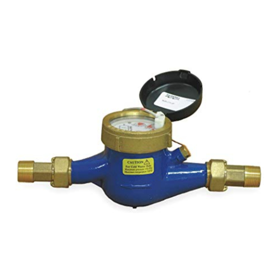
MD-Series meters use the multi-jet principle, which has
been an internationally-accepted standard for many
years. This type of meter is known for its wide range,
simplicity, and accuracy in low-quality water. The
impeller is centered in a ring of jets, with inlet jets on
one level and outlet jets on another. A gear train drives
the register totalizer dials. For pulse output, one of the
dials is replaced by a gear, which turns a magnet that
is detected by an encapsulated sensor threaded into
the outside of the lens. Pulse rate is determined by the
gear and the dial on which the gear is placed.
Mechanically, all MD-Series meters are the same. The
difference between MDE and MDR meters is in the sen-
sor. MDE meters use a solid-state, long-lasting Hall-
effect sensor, which requires power. They are suited
for use with SeaMetrics controls and metering pumps
(LMI for instance) which have sensor power. MDR
meters use a two-wire reed switch. They provide a dry
contact closure and do not require power. MDT meters
do not have a sensor, totalize only.
Features
Either MDE or MDR sensor
threads into lens without
removing top
Cast bronze body-
meets AWWA
specifications
Page 1 of 4
MD-Series Pulse Meter
Instructions
Specifications
Materials
Case
Internals
Magnet
Temperature
Max. Pressure
Accuracy
Sensor
MDE
MDR
Max. Current
MDE
MDR
Max. Voltage
MDE
MDR
Sensor Power (MDE) Minimum 6 mA at 12 VDC
Cable Length
Flow Rates (GPM):
3/4"
Minimum
0.22
Maximum
22
Connector for metering pump or
SeaMetrics control - optional
Union end couplings
for easy service
Cast bronze
Engineered thermoplastic
Ceramic permanent
105° F, 40° C
150 PSI operating
1-1/2% of reading
Solid state
Reed switch
20 mA
50 mA
24 VDC
24 VDC or 24 VAC
18 ft. standard, 2,000 ft. max.
1"
1-1/2"
2"
0.44
0.88
1.98
52
88
132
Advertisement
Table of Contents

Subscribe to Our Youtube Channel
Related Manuals for Seametrics MDE


Summary of Contents for Seametrics MDE
- Page 1 Max. Current 20 mA Mechanically, all MD-Series meters are the same. The 50 mA difference between MDE and MDR meters is in the sen- Max. Voltage sor. MDE meters use a solid-state, long-lasting Hall- 24 VDC effect sensor, which requires power. They are suited...
- Page 2 Installation Pulse Output. Both MDE and MDR sensors respond to a magnet which rotates on the face of the meter under the lens. The sensor turns on and off once each time the magnet passes under it. Sensors are designed for electronic control loads, and should not be used to switch power loads or line voltages.
- Page 3 3/4" - 10 gallons/pulse Standard (X1) gearset Pulse Drive Gear Gear Set Rate Position (X...) 20 P/G 10 P/G 2 P/G X0.1 move 1 P/G X0.1 3/4" gear to 5 G/P 10 G/P match 50 G/P 100 G/P 20 P/G 10 P/G X1 Drive gear 2 P/G...
- Page 4 Hinge Pin 30293 Lens, Glass 30289 MD-Series Parts 30296 O-ring 30300 Pickup, Reed Switch, 12' Cable 30346 Pickup, Solid State, 12' cable, MDE 30292 Slip Ring (pair) Part # FOR 3/4" MD METERS reed switch 16125 Calibration Plug slip ring w/cable...
Need help?
Do you have a question about the MDE and is the answer not in the manual?
Questions and answers