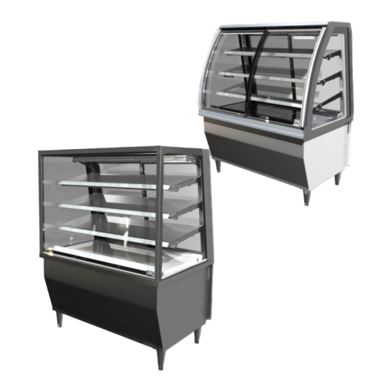
FPG INLINE 5000C Series Product Manual
Refrigerated cabinets
Hide thumbs
Also See for INLINE 5000C Series:
- Product manual (44 pages) ,
- Product manual (32 pages) ,
- Product manual (32 pages)
Table of Contents
Advertisement
Quick Links
Advertisement
Table of Contents

Related Manuals for FPG INLINE 5000C Series


Summary of Contents for FPG INLINE 5000C Series
- Page 1 Refrigerated Cabinets...
- Page 2 Copyright © August 2018 Future Products Group Limited. All rights reserved. No part of this publication may be reproduced, stored in a retrieval system, or transmitted in any form or by any means, electronic, mechanical, photocopying, recording or otherwise, without the prior written permission of Future Products Group Ltd.
-
Page 3: Table Of Contents
Table of Contents INTRODUCTION ......................... 7 Welcome ................................7 Future Products Group (FPG) ........................7 Guidance and Help ............................. 7 Warranty ................................7 Warranty Period ............................7 Liability Exceptions ............................. 8 Specific Exclusions ............................. 8 Assessment ..............................8 Time Limit ..............................8 Caution ............................... - Page 4 CLEANING ........................16 Cautions ................................. 16 Power ............................... 16 Water ................................ 16 Exterior ................................16 Louvers ..............................16 Painted and Metal Surfaces ........................16 Glass ................................ 16 Sliding Doors ............................17 Tilt Doors ..............................17 Interior................................17 Tilt Door Glass ............................17 End Glass ..............................
- Page 5 SERVICING ........................23 Lighting ................................23 Caution ..............................23 Circuit Breaker ............................23 Test Lighting Components ........................23 Access to LED Strips ..........................23 LED Strip Replacement ..........................23 Mains Lead ..............................24 Lead Replacement ........................... 24 Refrigeration ..............................24 Caution ..............................
- Page 6 ELECTRICAL CIRCUIT DIAGRAMS ................40 Model: IN 5C08 ............................40 Model: IN 5C12 ............................40 Model: IN 5C15 ............................41 Model: IN 5C18 ............................41 Model: IN 5C24 ............................42 SPARE PARTS ......................... 43 Cabinet Serial Number ..........................43 Location of Glass Parts ..........................44 MECHANICAL DRAWINGS ....................
-
Page 7: Introduction
INTRODUCTION Welcome REFRIGERATED CABINETS INTRODUCTION Future Welcome to the world of FPG! Our products are designed and engineered to Products give you the optimal performance that you deserve with innovative visual Group (FPG) merchandising appeal. We are confident that you will be delighted with your state of the art inline food service cabinet, and that it will become a valued appliance in your store. -
Page 8: Liability Exceptions
• Fair wear and tear. Assessment The liability under this warranty is dependent on an assessment by FPG, to determine the defect in workmanship or materials. Time Limit FPG does not guarantee that any service to be performed under this warranty will be carried out within any particular time limit. -
Page 9: Operation
OPERATION Cabinet Layout REFRIGERATED CABINETS OPERATION Tilt or Sliding The tilt door cabinet has a single front door and two Front Doors sliding rear doors, (four on the 2400 cabinet). The front door is hinged along the bottom edge, and is opened by pulling the top edge forward. -
Page 10: Controls
Controls REFRIGERATED CABINETS OPERATION Control Panel The control panel is mounted on the back of the cabinet, and houses: • The main power switch • The refrigeration switch • The Light switch • The refrigeration controller Power Switch To turn the power on, rotate the switch in a clockwise direction. -
Page 11: Temperature Controller
Controls cont. REFRIGERATED CABINETS - OPERATION Temperature The controller regulates the cabinet Controller temperature and controls the automatic defrost cycles. The display indicates the temperature of the returned air, before it enters the cooling coil. On integral condenser cabinets, the refrigeration gas pressure is also monitored, to protect the compressor from damage resulting from a blocked radiator or loss of gas. -
Page 12: Shelf Adjustment
Preparation cont. REFRIGERATED CABINETS - OPERATION Shelf To move the shelf support Adjustment brackets, remove all the shelves and then remove the rear sliding doors. Using two people, one on each bracket, slide the bracket upwards and disengage it from the support pillar. -
Page 13: Loading Restrictions
Preparation cont. REFRIGERATED CABINETS - OPERATION Loading It is important to leave adequate free space for Restrictions the refrigerated air to circulate within the cabinet. Product should be kept clear of the shaded areas, shown in the picture. A minimum clearance of 40 mm should be maintained below the light fittings and air deflectors. -
Page 14: Routines
Routines REFRIGERATED CABINETS OPERATION After Hours Ideally, cabinets should not be turned off after hours or at night. Products can either be left in the cabinet or placed in night storage. Shut the cabinet doors and turn off the lights. The cabinet will then operate on minimum load, and stay cold, ready for instant operation when next required. -
Page 15: Trouble Shooting
TROUBLE SHOOTING FAULT POSSIBLE CAUSE REMEDY The mains isolating switch on the wall, circuit breaker or Turn isolating switch circuit fuses are off at the power breaker or fuses on board High pressure switch tripped Clean condenser and radiator Switch cabinet off and on Cabinet does not operate/start Low pressure switch tripped Check gas pressure... -
Page 16: Cleaning
CLEANING Cautions REFRIGERATED CABINETS CLEANING Power ALWAYS TURN THE POWER SUPPLY OFF BEFORE CLEANING. Water THIS UNIT IS NOT WATERPROOF. DO NOT USE A WATER JET SPRAY TO CLEAN THE INTERIOR OR EXTERIOR OF THIS CABINET. Exterior REFRIGERATED CABINETS CLEANING Louvers Use a vacuum cleaner to remove dust and fluff from all of the ventilation louvers. -
Page 17: Sliding Doors
Exterior cont. REFRIGERATED CABINETS - CLEANING Sliding Doors Sliding glass doors can be removed for cleaning by sliding the door to central position, placing hands either side of the door, lifting up and then swinging out at the bottom. When replacing doors, make sure that the top is located in the correct slot, and the gliders are properly located on the correct bottom track. -
Page 18: End Glass
Interior cont. REFRIGERATED CABINETS - CLEANING End Glass The insides of the end glass panels can normally be cleaned after the shelf trays have been removed. Only remove the shelf lights and brackets etc. when carrying out longer term maintenance/cleaning. Trays, Shelves Stainless steel trays, shelves, grills etc. -
Page 19: Cleaning The Base Cavity
Interior cont. REFRIGERATED CABINETS - CLEANING Cleaning the Sweep out, or use a vacuum cleaner, to remove any debris from the cabinet Base Cavity base cavity. A Wet-and-Dry vacuum cleaner should be used, since there is likely to be some water in the bottom. -
Page 20: Routine
Routine REFRIGERATED CABINETS CLEANING Schedules To maintain optimum performance, cleaning schedules must be regular and thorough. Warning Failure to carry out routine cleaning/servicing schedules will void the warranty on the refrigeration equipment. Condenser For efficient refrigeration performance, the Radiator condenser radiator must be kept clean, (see Servicing, Condenser Radiator). -
Page 21: Installation
INSTALLATION Regulations REFRIGERATED CABINETS INSTALLATION Compliance It is very important that your inline food cabinet is installed correctly and that the with Local operation is correct before use. Installation must comply with local electrical, Requirements health & safety and hygiene requirements. Setting Up REFRIGERATED CABINETS INSTALLATION... -
Page 22: Cabinet Preparation
Setting Up cont. REFRIGERATED CABINETS - INSTALLATION Cabinet Remove all tapes, ties and packers, used Preparation to prevent movement during transit. Lift out the deck trays and grills to gain access to the cabinet well. Earthing WARNING-THIS APPLIANCE MUST BE EARTHED/GROUNDED The cabinet should be earthed via the earth lead in the mains cable. -
Page 23: Servicing
SERVICING Lighting REFRIGERATED CABINETS SERVICING Caution DO NOT service lights without isolating the cabinet at the main switch or unplugging it from the wall. Circuit Breaker All lighting circuits are protected by a circuit breaker, MCB. On IN C08/12/15&18 cabinets the circuit breaker and LED power supplies are located behind the control panel. -
Page 24: Mains Lead
Mains Lead REFRIGERATED CABINETS SERVICING Lead If damaged, the mains lead must ONLY be replaced by a qualified service Replacement person. Refrigeration REFRIGERATED CABINETS SERVICING Caution DO NOT attempt to service the refrigeration equipment without isolating the cabinet at the main switch or unplugging it from the wall. Access to To gain access to the Compressor... -
Page 25: Condensate Disposal
Refrigeration cont. REFRIGERATED CABINETS - SERVICING Condensate The automatic condensate removal, Disposal ACR system consists of a water tray, a water level detector and a boil-off element with an over temperature cut- out. If the element fails, it may be replaced by springing it from the mounting bracket. -
Page 26: Condenser Radiator
Refrigeration cont. REFRIGERATED CABINETS - SERVICING Condenser For efficient refrigeration IN 5C08 IN 5C12/15/18 Radiator performance, the condenser Cabinets Cabinets radiator must be kept clean. Failure to do this will lead to a build-up of dust, and restricted airflow will prevent the unit from working properly. -
Page 27: Temperature Regulator Xr40Cx
Refrigeration cont. REFRIGERATED CABINETS - SERVICING Temperature Model XR40CX is a microprocessor based Regulator controller. XR40CX It uses two NTC temperature probes, the first one, for temperature control, is located in the return air (air on), and the second one, located between the fins of the cooling coil, measures the defrost termination temperature. - Page 28 Refrigeration cont. REFRIGERATED CABINETS - SERVICING XR40CX Key FUNCTION Functions To display target set point; in programming mode it selects a parameter or confirm an operation (DEF) To start a manual defrost (UP): To see the max. stored temperature; in programming mode it browses the parameter codes or increases the displayed value (DOWN): To see the min stored temperature;...
- Page 29 Refrigeration cont. REFRIGERATED CABINETS - SERVICING XR40CX Press and release the key. Min & Max Lo will be displayed followed by the minimum temperature recorded. Recorded Press the key again or wait 5s to restore the normal display. Temperature Press and release the key.
- Page 30 Refrigeration cont. REFRIGERATED CABINETS - SERVICING XR40CX The The hidden menu includes all the parameters of the instrument. Hidden Menu TO ENTER THE HIDDEN MENU • Enter the Programming mode by pressing the keys for 3s, (the °C or °F LED starts blinking). •...
- Page 31 Refrigeration cont. REFRIGERATED CABINETS - SERVICING FPG Settings Note that the following settings are Dixell factory defaults. Refer to the Specification section for the correct FPG settings for your cabinet. Dixell Default Label Name Range Default Setting Settings Set point LS÷...
- Page 32 Refrigeration cont. REFRIGERATED CABINETS - SERVICING Label Name Range Default Setting Dixell Default Settings cont. Differential for temperat. alarm recovery (0,1 °C÷25,5°C) (1 °F÷45°F) Temperature alarm delay 0 ÷ 255 min Delay of temperature alarm at start up 0 ÷ 23h e 50’ Probe for temperat.
-
Page 33: Xr40Cx Connections
Refrigeration cont. REFRIGERATED CABINETS - SERVICING XR40CX Message Cause Outputs Alarm Signals Room probe failure Compressor output acc. to par. Con and COF Evaporator probe failure Defrost end is timed Third probe failure Outputs unchanged Fourth probe failure Outputs unchanged Maximum temperature alarm Outputs unchanged. -
Page 34: Gaskets
Gaskets REFRIGERATED CABINETS SERVICING Qlon Gaskets The front door aperture is fitted with Qlon gaskets along the top, bottom and on either side. The gaskets are foam filled, and have T section bases, which slide into aluminium extrusions. Gasket The top aluminium extrusion is in two halves, Replacement with a 20mm gap at the centre. -
Page 35: Specifications
SPECIFICATIONS Mechanical REFRIGERATED CABINETS SPECIFICATIONS CABINET MODEL IN 5C08 IN 5C12 IN 5C15 IN 5C15 IN 5C18 IN 5C18 IN 5C24 IN 5C24 Remote Remote Remote Height (150mm Feet) 1443 mm 1443 mm 1443 mm 1443 mm 1443 mm 1443 mm 1443 mm 1443 mm Height (100mm Feet) -
Page 36: Electrical
Electrical REFRIGERATED CABINETS SPECIFICATIONS CABINET MODEL IN 5C15 IN 5C18 IN 5C24 IN 5C08 IN 5C12 IN 5C15 IN 5C18 IN 5C24 Remote Remote Remote Voltage 220-240 V 50 Hz 1 230 W 300W 360W 1.01 kW 1.21 kW 1.54 kW excl. -
Page 37: Controller Setting
Controller Setting REFRIGERATED CABINETS SPECIFICATIONS Integral Remote Integral Remote Dixell XR40CX Settings Parameter Condenser Condenser Controlled Controlled Units/Range Models Models Ambient Ambient Set Point degC Differential degC Anti Short Cycle Delay Comp On Time - Faulty Probe Comp Off Time - Faulty Probe Defrost Terminate Temp degC Interval Between Defrosts... -
Page 38: Compliance
Cabinets can also be supplied with an operating temperature of +16°C to +18°C Improvements REFRIGERATED CABINETS SPECIFICATIONS Ongoing FPG reserves the right to change specifications and construction, as part of Development ongoing product improvement. Part No.26107 Rev J August 2018 - 38 -... -
Page 39: Equipment Disposal
Equipment Disposal REFRIGERATED CABINETS SPECIFICATIONS Specialist Specialist disposal procedures are required for the safe removal of refrigerant Disposal gasses and potentially flammable foam materials. Pentane, Dimethyl Ether, Isobutene, Butane and Propane may be present. Hazardous The cabinet does not contain any of the following, in its construction: Substances Asbestos PCBs (Oils containing polychlorinated biphenyl) -
Page 40: Electrical Circuit Diagrams
ELECTRICAL CIRCUIT DIAGRAMS Model: IN 5C08 Inline 5000 Series, 800mm Refrigerated Cabinet Model: IN 5C12 Inline 5000 Series, 1200mm Refrigerated Cabinet Part No.26107 Rev J August 2018 - 40 - Inline 5000 Series Cabinets... -
Page 41: Model: In 5C15
ELECTRICAL CIRCUIT DIAGRAMS Continued Model: IN 5C15 Inline 5000 Series, 1500mm Refrigerated Cabinet Model: IN 5C18 Inline 5000 Series, 1800mm Refrigerated Cabinet IN 5C08/12/15/18/24. - 41 - © Future Products Group... -
Page 42: Model: In 5C24
ELECTRICAL CIRCUIT DIAGRAMS Continued Model: IN 5C24 Inline 5000 Series, 2400mm Refrigerated Cabinet Part No.26107 Rev J August 2018 - 42 - Inline 5000 Series Cabinets... -
Page 43: Spare Parts
When ordering spare parts, please quote the Serial Number printed on the label Number fixed to the control panel. This will enable FPG to ensure that spare parts are fully compatible with the cabinet. To satisfy warranty conditions, use only FPG supplied spare parts. -
Page 44: Location Of Glass Parts
Location of In the following table, handed glass parts are labelled as viewed from the REAR Glass Parts of the cabinet. Part Description FPG Part Number 5K LH/RH Curved End Glass 21191 5K LH DG Square End Glass 17650 5K RH DG Square End Glass... -
Page 45: Mechanical Drawings
MECHANICAL DRAWINGS Cabinet Feet These drawings show cabinets fitted with the standard 150mm tapered feet. Alternative 100mm cylindrical feet are available for special orders. These will reduce the overall cabinet height, and also have only -0 +25mm of adjustment. Tilt Door Cabinets Types IN 5C08/12/15 IN 5C08/12/15/18/24. -
Page 46: Sliding Door Cabinets, Types In 5C08/12/15
Sliding Door Cabinets, Types IN 5C08/12/15 Part No.26107 Rev J August 2018 - 46 - Inline 5000 Series Cabinets... -
Page 47: Tilt Door Cabinets, Type In 5C18
Tilt Door Cabinets, Type IN 5C18 IN 5C08/12/15/18/24. - 47 - © Future Products Group... -
Page 48: Sliding Door Cabinets, Type In 5C18
Sliding Door Cabinets, Type IN 5C18 Part No.26107 Rev J August 2018 - 48 - Inline 5000 Series Cabinets... -
Page 49: Square Glass Cabinets Types In 5C08/12/15/18
Square Glass Because the front face of Square glass cabinets is vertical, deeper shelves Cabinets Types can be fitted in the upper two levels. This increases the display area by IN 5C08/12/15/18 about 10%. A 2400mm version of the square format cabinet is also available. It has split shelves, in a 2 x 1200mm configuration. -
Page 50: Cabinet Type In 5C24
Cabinet Type Although shown with front sliding doors, this cabinet is also available with a IN 5C24 front tilt door. Part No.26107 Rev J August 2018 - 50 - Inline 5000 Series Cabinets... -
Page 51: Square Glass Cabinet Type In 5C24
Square Glass Although shown with front sliding doors, this cabinet is also available with a Cabinet Type front tilt door. IN 5C24 IN 5C08/12/15/18/24. - 51 - © Future Products Group... - Page 52 Part No.26107 Rev J August 2018 For full contact details please visit the Contacts page on FPGWORLD.COM or email us at support@fpgworld.com In line with policy to continually develop and improve its products, Future Products Group reserves the right to change specifications and design without notice. AUSTRALIA CHINA | ASIA EUROPE...
Need help?
Do you have a question about the INLINE 5000C Series and is the answer not in the manual?
Questions and answers