TP-Link TL-SG1008PE Installation Manual
Unmanaged/easy smart rackmountable switch
Hide thumbs
Also See for TL-SG1008PE:
- Installation manual (32 pages) ,
- Installation manual (32 pages) ,
- Installation manual (28 pages)

Related Manuals for TP-Link TL-SG1008PE


Summary of Contents for TP-Link TL-SG1008PE
-
Page 1: Installation Guide
Business Networking Solution Installation Guide Unmanaged/Easy Smart Rackmountable Switch... - Page 3 Conventions • Some models featured in this guide may be unavailable in your country or region. For local sales information, visit https://www.tp-link.com. • The figures in Chapter 2 and Chapter 3 are for demonstration purposes only. Your switch may differ in appearance from that depicted.
-
Page 4: Table Of Contents
Contents Chapter 1 Introduction ––––––––––––––––––––––– 1 Product Overview ............. 1 Appearance ................ 1 Chapter 2 Installation –––––––––––––––––––––––– 9 Package Contents ............9 Safety Precautions ............9 Installation Tools ............... 11 Product Installation ............11 Chapter 3 Connection –––––––––––––––––––––––– 13 Ethernet Port ..............13 SFP Port ................ -
Page 5: Chapter 1 Introduction
100 Mbps or 1000 Mbps. TL-SG1008PE/TL-SG1016PE/TL-SG1218MPE is also a Power Sourcing Equipment (PSE*). The RJ45 ports 1 to 8 on the TL-SG1008PE and TL-SG1016PE and all 16 Gigabit RJ45 ports on the TL-SG1218MPE support Power over Ethernet (PoE*) function, which can automatically detect and supply power with those powered devices (PDs*) complying with IEEE 802.3af and IEEE 802.3at. - Page 6 Unmanaged/Easy Smart Rackmountable Switch The front panel of TL-SF1048 is shown as the following figure. Figure 1-3 Front Panel of TL-SF1048 10/100Mbps LEDs RJ45 Port The front panel of TL-SF1016DS is shown as the following figure. Figure 1-4 Front Panel of TL-SF1016DS LEDs 10/100Mbps RJ45 Port...
- Page 7 Unmanaged/Easy Smart Rackmountable Switch The front panel of TL-SG1016 is shown as the following figure. Figure 1-7 Front Panel of TL-SG1016 LEDs 10/100/1000Mbps RJ45 Port The front panel of TL-SG1024 is shown as the following figure. Figure 1-8 Front Panel of TL-SG1024 LEDs 10/100/1000Mbps RJ45 Port...
- Page 8 Unmanaged/Easy Smart Rackmountable Switch The front panel of TL-SG1024S is shown as the following figure. Figure 1-11 Front Panel of TL-SG1024S LEDs 10/100/1000Mbps RJ45 Port The front panel of TL-SG1016D is shown as the following figure. Figure 1-12 Front Panel of TL-SG1016D LEDs 10/100/1000Mbps RJ45 Port...
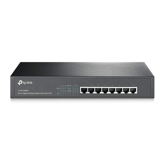
- Page 9 Figure 1-15 Front Panel of TL-SG1024DE LEDs Reset 10/100/1000Mbps RJ45 Port The front panel of TL-SG1008PE is shown as the following figure. Figure 1-16 Front Panel of TL-SG1008PE 10/100/1000Mbps RJ45 Port LEDs The front panel of TL-SG1016PE is shown as the following figure.
- Page 10 Flashing: The PoE power circuit may be in short or the power current may be overloaded. Off: No PD is connected to the corresponding port or no power is supplied according to the power limits of the port. Note: Only for TL-SG1008PE. PoE Status On: The port is connecting and supplying power to a PD.
- Page 11 Designed to connect to the device with a bandwidth of 10 Mbps, 100 Mbps or 1000 Mbps. For TL-SG1016PE and TL-SG1008PE, ports 1 to 8 can also provide power for PDs. For TL-SG1218MPE, ports 1 to 16 can also provide power for PDs.
- Page 12 PE (Protecting Earth) cable of AC cord or with Ground Cable. For detailed information, refer to the Lightning Protection Guide from the Related Documents of our website: https://www.tp-link.com/en/configuration-guides/lightning_protection_guide/?configurationId=2962 Power Socket Plug the female connector of the power cord directly into the power socket and plug the male connector into an AC outlet.
-
Page 13: Chapter 2 Installation
Unmanaged/Easy Smart Rackmountable Switch Chapter 2 Installation Package Contents Make sure that the package contains the following items. If any of the listed items is damaged or missing, contact your distributor. One Switch This Installation Guide One Power Cord Two mounting brackets, eight One Resource CD screws and four rubber feet Note:... - Page 14 Unmanaged/Easy Smart Rackmountable Switch Site Requirements ■ Temperature/Humidity 40°C 0°C Keep the equipment room at an appropriate level of temperature and humidity. Too much or too little humidity may lead to bad insulation, leakage of electricity, mechanical property changes, and corrosion. High temperatures may accelerate aging of the insulation materials, significantly shortening the service life of the device.
-
Page 15: Installation Tools
Note: For detailed lightning protection measures, refer to the Lightning Protection Guide from the Related Documents of our website: https://www.tp-link.com/en/configuration-guides/lightning_protection_guide/?configurationId=2962 Installation Site When installing the device on a rack or a flat workbench, attach much importance to the following items: The rack or workbench is flat, stable, and sturdy enough to support the weight of 5.5 kg at least. -
Page 16: Rack Installation
Unmanaged/Easy Smart Rackmountable Switch Figure 2-1 Desktop Installation Feet Bottom of the Device Notch Rack Installation ■ To install the device in an EIA standard-sized, 19-inch rack, follow the instructions described below: 1. Check the efficiency of the grounding system and the stability of the rack. 2. -
Page 17: Chapter 3 Connection
Unmanaged/Easy Smart Rackmountable Switch Chapter 3 Connection Ethernet Port Connect an Ethernet port of the switch to the computer by RJ45 cable as the following figure shows. Figure 3-1 Connecting the RJ45 Port RJ45 Port RJ45 Cable SFP Port The following figure demonstrates the connection of SFP port to an SFP module. Figure 3-2 Inserting the SFP Module SFP Slot... -
Page 18: Power On
Unmanaged/Easy Smart Rackmountable Switch The device is correctly connected to other network devices. ■ Power On Plug the negative connector of the provided power cord into the power socket of the device and plug the positive connector into a power outlet as the following figure shows. Figure 3-3 Connecting to Power Supply Note:... -
Page 19: Using The Configuration Utility
You can find the configuration utility on the resource CD or download it from the official website: https://www.tp-link.com/en/download-center.html For detailed information about using the configuration utility, refer to the Easy Smart Configuration Utility User Guide on the resource CD. You can find the latest version of this guide on the official website: https://www.tp-link.com/en/download-center.html Contents... -
Page 20: Appendix A Troubleshooting
Appendix A Troubleshooting Q1. What could I do if I forgot the username and password of the Switch? With the switch powered on, press the Reset button for at least 5 seconds to reset the system. The system will be reset to the factory default settings, and the default login user name and password are both admin. -
Page 21: Appendix B Specifications
1000BASE-X: 1488095 pps/Port (for TL-SG1218MPE) LEDs Power, Link/Act (for TL-SG1048/TL-SF1016/TL-SF1016DS/TL-SF1024/TL- SF1024D/TL-SF1048) Power, 1000Mbps, Link/Act, PoE Status, PoE MAX (for TL-SG1008PE) PWR, Speed, PoE Status, PoE MAX, FAN (for TL-SG1016PE) PWR, Link/Act, PoE Status, PoE MAX, FAN (for TL-SG1218MPE) Power, 1000Mbps, Link/Act (for other switches) - Page 22 Operating Temperature 0°C to 40°C (32 to 104°F) 0°C to 50°C (32 to 122°F) (for TL-SG1218MPE) Storage Temperature -40°C to 70°C (-40 to 158°F) Operating Humidity 10% to 90%RH Non-condensing Storage Humidity 5% to 90%RH Non-condensing...
-
Page 23: Ce Mark Warning
EU declaration of conformity TP-Link hereby declares that the device is in compliance with the essential requirements and other relevant provisions of directives 2014/30/EU, 2014/35/EU, 2009/125/EC and 2011/65/EU. The original EU declaration of conformity may be found at https://www.tp-link.com/en/ce Продукт... - Page 24 For technical support, the user guide and more information, please visit https://www.tp-link.com/support, or simply scan the QR code. © 2019 TP-Link 7106508362 REV13.1.0...