Endress+Hauser Dosimag Modbus RS485 Operating Instructions Manual
Electromagnetic flowmeter
Hide thumbs
Also See for Dosimag Modbus RS485:
- Operating instructions manual (140 pages) ,
- Operating instructions manual (84 pages) ,
- Operating instructions manual (76 pages)

Related Manuals for Endress+Hauser Dosimag Modbus RS485


Summary of Contents for Endress+Hauser Dosimag Modbus RS485
-
Page 1: Operating Instructions
Products Solutions Services BA01321D/06/EN/03.17 71349516 Valid as of version 03.00.zz (Device firmware) Operating Instructions Dosimag Modbus RS485 Electromagnetic flowmeter... - Page 2 • The manufacturer reserves the right to modify technical data without prior notice. Your Endress+Hauser Sales Center will supply you with current information and updates to these instructions. Endress+Hauser...
-
Page 3: Table Of Contents
Dosimag Modbus RS485 Table of contents Table of contents 6.2.7 Nominal diameter and flow ..23 Document information ....5 Post-installation check . - Page 4 13.2 Measuring and test equipment ... . 59 13.3 Endress+Hauser services ....59 Repair ......60 14.1 General notes .
-
Page 5: Document Information
Dosimag Modbus RS485 Document information Document information Document function These Operating Instructions contain all the information that is required in various phases of the life cycle of the device: from product identification, incoming acceptance and storage, to mounting, connection, operation and commissioning through to troubleshooting, maintenance and disposal. -
Page 6: Symbols In Graphics
• The W@M Device Viewer : Enter the serial number from the nameplate (www.endress.com/deviceviewer) • The Endress+Hauser Operations App: Enter the serial number from the nameplate or scan the 2-D matrix code (QR code) on the nameplate. For a detailed list of the individual documents along with the documentation code... -
Page 7: Standard Documentation
Registered trademarks Modbus ® Registered trademark of SCHNEIDER AUTOMATION, INC. TRI-CLAMP ® Registered trademark of Ladish & Co., Inc., Kenosha, USA Applicator ® , FieldCare ® , DeviceCare ® Registered or registration-pending trademarks of the Endress+Hauser Group Endress+Hauser... -
Page 8: Basic Safety Instructions
Keep within the specified pressure and temperature range. Verification for borderline cases: ‣ For special fluids and fluids for cleaning, Endress+Hauser is glad to provide assistance in verifying the corrosion resistance of fluid-wetted materials, but does not accept any Endress+Hauser... -
Page 9: Workplace Safety
It meets general safety standards and legal requirements. It also complies with the EC directives listed in the device-specific EC Declaration of Conformity. Endress+Hauser confirms this by affixing the CE mark to the device. - Page 10 Basic safety instructions Dosimag Modbus RS485 IT security measures in line with operators' security standards and designed to provide additional protection for the device and device data transfer must be implemented by the operators themselves. Endress+Hauser...
-
Page 11: Product Description
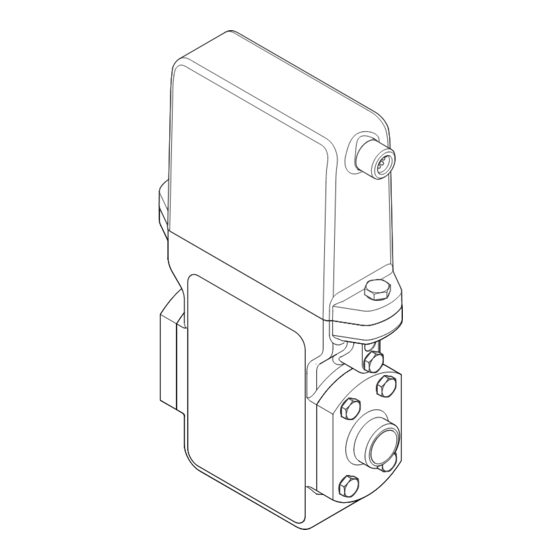
Dosimag Modbus RS485 Product description Product description The device consists of a transmitter and a sensor. The device is available as a compact version: The transmitter and sensor form a mechanical unit. Product design A0026624 1 Important components of the measuring device... -
Page 12: Incoming Acceptance And Product
A0028673 and documents present? • If one of the conditions is not satisfied, contact your Endress+Hauser Sales Center. • Depending on the device version, the CD-ROM might not be part of the delivery! The Technical Documentation is available via the Internet or via the Endress+Hauser Operations App, see the "Product identification"... -
Page 13: Sensor Nameplate
"Supplementary device-dependent documentation" → 7 • The W@M Device Viewer: Enter the serial number from the nameplate (www.endress.com/deviceviewer) • The Endress+Hauser Operations App: Enter the serial number from the nameplate or scan the 2-D matrix code (QR code) on the nameplate. 4.2.1... -
Page 14: Symbols On Measuring Device
Incoming acceptance and product identification Dosimag Modbus RS485 4.2.2 Symbols on measuring device Symbol Meaning WARNING! This symbol alerts you to a dangerous situation. Failure to avoid this situation can result in serious or fatal injury. Reference to documentation Refers to the corresponding device documentation. -
Page 15: Storage And Transport
Dosimag Modbus RS485 Storage and transport Storage and transport Storage conditions Observe the following notes for storage: • Store in the original packaging to ensure protection from shock. • Do not remove protective covers or protective caps installed on process connections. -
Page 16: Installation
Installation Dosimag Modbus RS485 Installation Installation conditions 6.1.1 Mounting position Mounting location A0029343 Preferably install the sensor in an ascending pipe, and ensure a sufficient distance to the next pipe elbow: h ≥ 2 × DN Installation in down pipes Install a siphon with a vent valve downstream of the sensor in down pipes whose length h ≥... - Page 17 Dosimag Modbus RS485 Installation Orientation The direction of the arrow on the sensor nameplate helps you to install the sensor according to the flow direction (direction of medium flow through the piping). Orientation Recommendation Vertical orientation A0015591 Horizontal orientation, transmitter at...
- Page 18 Installation Dosimag Modbus RS485 A0003768 Measuring device Filling valve Container Filling systems The pipe system must be completely full to ensure optimum measurement. A0003795 4 Filling system Measuring device Filling valve Container Inlet and outlet runs If possible, install the sensor upstream from fittings such as valves, T-pieces or elbows.
-
Page 19: Requirements From Environment And Process
Dosimag Modbus RS485 Installation Installation dimensions For the dimensions and installation lengths of the device, see the "Technical Information" document, "Mechanical construction" section. 6.1.2 Requirements from environment and process Ambient temperature range Transmitter –40 to +60 °C (–40 to +140 °F) Sensor –40 to +60 °C (–40 to +140 °F) -
Page 20: Special Mounting Instructions
Installation Dosimag Modbus RS485 In the event of very strong vibrations, the pipe and sensor must be supported and fixed. • For information on the shock resistance of the measuring system → 69 • For information on the vibration resistance of the measuring system → 69... -
Page 21: Mounting The Measuring Device
Dosimag Modbus RS485 Installation Circular filling system A0003761 Tank Measuring device Batching valve Vessel Linear filling system A0003762 Tank Measuring device Batching valve Vessel Mounting the measuring device 6.2.1 Required tools For sensor For flanges and other process connections: • Screws, nuts, seals etc. are not included in the scope of supply and must be provided by the customer. -
Page 22: Mounting The Measuring Device
Installation Dosimag Modbus RS485 2. Remove any protective covers or protective caps present from the sensor. 3. Remove stick-on label on the electronics compartment cover. 6.2.3 Mounting the measuring device WARNING Danger due to improper process sealing! ‣ Ensure that the inside diameters of the gaskets are greater than or equal to that of the process connections and piping. -
Page 23: Seals
Dosimag Modbus RS485 Installation 6.2.6 Seals When mounting the process connections, make sure that the seals in question are dry, clean, undamaged and correctly centered. • The screws must be firmly tightened. The process connection forms a metal connection with the sensor, which ensures a defined compression of the seal. -
Page 24: Electrical Connection
Electrical connection Dosimag Modbus RS485 Electrical connection The measuring device does not have an internal circuit breaker. For this reason, assign the measuring device a switch or power-circuit breaker so that the power supply line can be easily disconnected from the mains. -
Page 25: Pin Assignment, Device Plug
Dosimag Modbus RS485 Electrical connection 7.1.3 Pin assignment, device plug Device version: Modbus RS485, status output and status input Order code for "Output, input", option 4: Modbus RS485, 1 switch output (batch), 1 status input RSE 8 RSE 5 M12x1... - Page 26 Electrical connection Dosimag Modbus RS485 Device version: Modbus RS485 , 2 status outputs and status input Order code for "Output, input", option 5: Modbus RS485, 2 switch outputs (batch), 1 status input RSE 8 RSE 5 M12x1 M12x1 A0032571 7...
- Page 27 Dosimag Modbus RS485 Electrical connection Device version: Modbus RS485 (custody transfer mode) Order code for "Output, input", option 6 (device version for custody transfer mode): Modbus RS485 RSE 8 M12x1 A0032572 8 Connection to device Coupling: Supply voltage, Modbus RS485...
-
Page 28: Requirements For The Supply Unit
Electrical connection Dosimag Modbus RS485 7.1.4 Requirements for the supply unit Supply voltage DC 24 V (nominal voltage: DC 20 to 30 V) • The power unit must be tested to ensure that it meets safety requirements (e.g. PELV, SELV). -
Page 29: Post-Connection Check
Dosimag Modbus RS485 Electrical connection To guarantee IP67 degree of protection, Type 4X enclosure, carry out the following steps after the electrical connection: ‣ Tighten all device plugs. Post-connection check Is the device undamaged (visual inspection)? Does the supply voltage in the system match the specifications on the device' s nameplate? ... -
Page 30: Operation Options
Connecting the operating tool Using the service adapter and Commubox FXA291 Operation and configuration can be performed using the Endress+Hauser FieldCare or DeviceCare service and configuration software. The device is connected to the USB port of the computer via the service adapter and Commubox FXA291. -
Page 31: Fieldcare
FieldCare Function scope FDT-based plant asset management tool from Endress+Hauser. It can configure all smart field devices in a system and helps you manage them. By using the status information, it is also a simple but effective way of checking their status and condition. -
Page 32: Devicecare
DeviceCare Function scope Tool to connect and configure Endress+Hauser field devices. The fastest way to configure Endress+Hauser field devices is with the dedicated "DeviceCare" tool. Together with the device type managers (DTMs) it presents a convenient, comprehensive solution. For details, see Innovation Brochure IN01047S Source for device description files See information →... -
Page 33: System Integration
Dosimag Modbus RS485 System integration System integration Overview of device description files 9.1.1 Current version data for the device Firmware version 03.00.zz • On the title page of the Operating instructions • On transmitter nameplate • Firmware version Diagnostics menu → Device information submenu →... -
Page 34: Register Information
System integration Dosimag Modbus RS485 Code Name Description Application Write single Master writes a new value to one Write only 1 device parameter registers Modbus register of the measuring Example: reset totalizer device. Use function code 16 to write multiple registers with just 1 telegram. - Page 35 Dosimag Modbus RS485 System integration Structure of the Modbus data map The Modbus data map consists of two data sets: • Scan list: Configuration area The device parameters to be grouped are defined in a list in that their Modbus RS485 register addresses are entered in the list.
- Page 36 System integration Dosimag Modbus RS485 Data area Device parameter value Modbus RS485 Data type* Access** register Value of scan list register 0 5051 Integer/float Read/write Value of scan list register 1 5053 Integer/float Read/write Value of scan list register ...
-
Page 37: Commissioning
Dosimag Modbus RS485 Commissioning Commissioning 10.1 Function check Before commissioning the measuring device: ‣ Make sure that the post-installation and post-connection checks have been performed. • "Post-installation check" checklist → 23 • "Post-connection check" checklist → 29 10.2 Switching on the measuring device ‣... -
Page 38: Defining The Tag Name
Commissioning Dosimag Modbus RS485 10.4.1 Defining the tag name To enable fast identification of the measuring point within the system, you can enter a unique designation using the Device tag parameter and thus change the factory setting. • The number of characters displayed depends on the characters used. -
Page 39: Configuring The Switch Output
Dosimag Modbus RS485 Commissioning Navigation "Setup" menu → Status input Structure of the submenu ‣ Status input Assign status input Active level Response time status input Parameter overview with brief description Parameter Prerequisite Description Selection / User Factory setting entry Assign status input... - Page 40 Commissioning Dosimag Modbus RS485 Parameter overview with brief description Parameter Description Selection Factory setting Batch profile Select suitable profile for fluid configured by • Profile 1 Profile 1 customer. • Profile 2 • Profile 3 • Profile 4 • Profile 5 •...
-
Page 41: Configuring The Communication
Dosimag Modbus RS485 Commissioning 10.4.5 Configuring the communication interface The Communication submenu guides you systematically through all the parameters that have to be configured for selecting and setting the communication interface. Navigation "Setup" menu → Communication ‣ Communication Bus address... -
Page 42: Low Flow Cut Off
Commissioning Dosimag Modbus RS485 Parameter Description User entry / Selection Factory setting Assign diagnostic behavior Select diagnostic behavior for MODBUS • Off Alarm communication. • Alarm or warning • Warning • Alarm Failure mode Select measured value output behavior when • NaN value... -
Page 43: Sensor Adjustment
Dosimag Modbus RS485 Commissioning Navigation "Setup" menu → Advanced setup ‣ Advanced setup Enter access code ‣ → 43 Sensor adjustment ‣ Totalizer 1 to n → 43 ‣ Administration → 56 10.5.1 Sensor adjustment The Sensor adjustment submenu contains parameters that pertain to the functionality of the sensor. -
Page 44: Simulation
Commissioning Dosimag Modbus RS485 Parameter overview with brief description Parameter Prerequisite Description Selection Factory setting Assign process variable – Select process variable for • Off Volume flow totalizer. • Volume flow Volume unit The Volume flow option is Select volume unit. -
Page 45: Operation
Dosimag Modbus RS485 Operation Operation 11.1 Reading device locking status Device active write protection: Locking status parameter Navigation "Operation" menu → Locking status Function scope of "Locking status" parameter Options Description Temporarily locked Write access to the parameters is temporarily lock due to device-internal processing (e.g. -
Page 46: Totalizer
Operation Dosimag Modbus RS485 Navigation "Diagnostics" menu → Measured values → Process variables ‣ Process variables Volume flow Parameter overview with brief description Parameter Description User interface Volume flow Displays the volume flow currently measured. Signed floating-point number Dependency The unit is taken from the Volume flow unit parameter 11.3.2... -
Page 47: Performing A Totalizer Reset
Dosimag Modbus RS485 Operation Navigation "Diagnostics" menu → Measured values → Input values Structure of the submenu ‣ Input values Value status input Parameter overview with brief description Parameter Description User interface Value status input Shows the current input signal level. -
Page 48: Batching Control
Operation Dosimag Modbus RS485 Parameter overview with brief description Parameter Prerequisite Description Selection / User Factory setting entry Control Totalizer In the Assign process variable Control totalizer value. • Totalize Totalize parameter (→ 44) of the • Reset + hold Totalizer 1 to n submenu, the •... - Page 49 Dosimag Modbus RS485 Operation Switch status 2 Reset overall batching quantity Parameter overview with brief description Parameter Description Selection / User interface Factory setting Batch control Switch the batch on and off. • Start Stop • Stop Batch counter Shows number of passed batch procedures.
-
Page 50: Diagnostics And Troubleshooting
Diagnostics and troubleshooting Dosimag Modbus RS485 Diagnostics and troubleshooting 12.1 General troubleshooting For access Problem Possible causes Remedy No write access to parameters Current user role has limited access Check access authorization status . authorization No connection via Modbus RS485... -
Page 51: Calling Up Remedy Information
Dosimag Modbus RS485 Diagnostics and troubleshooting Xxxxxx/…/…/ Device name: Xxxxxxx Mass flow: kg/h 12.34 Device tag: Xxxxxxx Volume flow: 12.34 m /h ³ Status signal: Function check (C) Xxxxxx Diagnostics 1: C485 Simu... Remedy information: Deactivate... Failure (F) Access status tooling:... -
Page 52: Diagnostic Information Via Communication
Diagnostics and troubleshooting Dosimag Modbus RS485 2. On the right in the working area, mouse over the parameter. A tool tip with remedy information for the diagnostic event appears. 12.3 Diagnostic information via communication interface 12.3.1 Reading out diagnostic information Diagnostic information can be read out via Modbus RS485 register addresses. -
Page 53: Overview Of Diagnostic Information
Dosimag Modbus RS485 Diagnostics and troubleshooting You can assign the following options to the diagnostic number as the diagnostic behavior: Options Description Alarm Measurement is interrupted. Measured value output via Modbus RS485 and totalizers assume the defined alarm condition. A diagnostic message is generated. -
Page 54: Pending Diagnostic Events
Diagnostics and troubleshooting Dosimag Modbus RS485 Diagnostic Short text Remedy instructions Status signal Diagnostic number [from the behavior factory] [from the factory] Dataset 1. Check data set file Warning 2. Check device configuration 3. Up- and download new configuration Frequency output 1 to n 1. Check process Warning 2. -
Page 55: Diagnostic List
Dosimag Modbus RS485 Diagnostics and troubleshooting Previous diagnostics Parameter overview with brief description Parameter Prerequisite Description User interface Actual diagnostics A diagnostic event has occurred. Shows the current occured diagnostic Symbol for diagnostic event along with its diagnostic behavior, diagnostic code information. -
Page 56: Overview Of Information Events
Diagnostics and troubleshooting Dosimag Modbus RS485 12.8.3 Overview of information events Unlike a diagnostic event, an information event is displayed in the event logbook only and not in the diagnostic list. Info number Info name I1000 --------(Device ok) I1089 Power on... - Page 57 Dosimag Modbus RS485 Diagnostics and troubleshooting Order code Extended order code 1 Extended order code 2 Extended order code 3 ENP version Parameter overview with brief description Parameter Description User interface Factory setting Device tag Display the name for the measuring point.
-
Page 58: 12.11 Firmware History
"Manufacturer' s information" document. The manufacturer' s information is available: • In the Downloads area of the Endress+Hauser web site: www.endress.com → Downloads • Specify the following details: –... -
Page 59: Maintenance
Replacement seals (accessory part) → 62 13.2 Measuring and test equipment Endress+Hauser offers a wide variety of measuring and test equipment, such as W@M or device tests. Your Endress+Hauser Sales Center can provide detailed information on the services. For a list of some of the measuring and test equipment, refer to the "Accessories"... -
Page 60: Repair
14.3 Endress+Hauser services Endress+Hauser offers a wide range of services. Your Endress+Hauser Sales Center can provide detailed information on the services. 14.4 Return The measuring device must be returned if it is need of repair or a factory calibration, or if the wrong measuring device has been delivered or ordered. -
Page 61: Disposing Of The Measuring Device
Dosimag Modbus RS485 Repair WARNING Danger to persons from process conditions. ‣ Beware of hazardous process conditions such as pressure in the measuring device, high temperatures or aggressive fluids. Carry out the mounting and connection steps from the chapters "Mounting the measuring device"... -
Page 62: Accessories
Various accessories, which can be ordered with the device or subsequently from Endress +Hauser, are available for the device. Detailed information on the order code in question is available from your local Endress+Hauser sales center or on the product page of the Endress+Hauser website: www.endress.com. -
Page 63: Service-Specific Accessories
Device status, spare parts, device-specific documentation. The application already contains the data of your Endress+Hauser device. Endress +Hauser also takes care of maintaining and updating the data records. W@M is available: •... -
Page 64: Technical Data
Technical data Dosimag Modbus RS485 Technical data 16.1 Application Depending on the version ordered, the measuring device can also measure potentially explosive, flammable, poisonous and oxidizing media. To ensure that the device remains in proper operating condition for its service life, use the measuring device only for media against which the process-wetted materials are sufficiently resistant. -
Page 65: Output
Dosimag Modbus RS485 Technical data Flow characteristic values in US units Recommended Nominal diameter Factory settings flow Low flow cut off Max. full scale value Pulse value (v ~ 0.13 ft/s) [in] [gal/s] [oz fl] [oz fl/s] ⁵⁄₃₂ 0.035 0.0002 0.02... - Page 66 Technical data Dosimag Modbus RS485 Number of switching Unlimited cycles Assignable functions • Open • Closed • Batching Signal on alarm Depending on the interface, failure information is displayed as follows: Modbus RS485 Failure mode Choose from: • NaN value instead of current value •...
-
Page 67: Power Supply
Dosimag Modbus RS485 Technical data 16.5 Power supply Terminal assignment → 24 Pin assignment, device plug → 25 Supply voltage DC 24 V (nominal voltage: DC 20 to 30 V) • The power unit must be tested to ensure that it meets safety requirements (e.g. -
Page 68: Installation
Technical data Dosimag Modbus RS485 Installation • Inlet run > 10 × DN • Outlet run > 5 × DN • Sensor and transmitter grounded. • The sensor is centered in the pipe. Maximum measured error Error limits under reference operating conditions o.r. -
Page 69: Process
Dosimag Modbus RS485 Technical data • Protect the measuring device against direct sunlight during storage in order to avoid unacceptably high surface temperatures. • Select a storage location where moisture cannot collect in the measuring device as fungus or bacteria infestation can damage the liner. -
Page 70: 16.10 Mechanical Construction
Technical data Dosimag Modbus RS485 Ambient temperature Medium temperature Light-gray area: standard fluid temperature range Dark-gray area: fluid temperature range for cleaning Conductivity • ≥ 5 μS/cm for liquids in general • ≥ 10 μS/cmfor demineralized water Pressure-temperature An overview of the pressure-temperature ratings for the process connections is ratings provided in the "Technical Information"... - Page 71 Dosimag Modbus RS485 Technical data Weight Compact version Weight in SI units DN [mm] Weight [kg] Weight in US units DN [in] Weight [lbs] ⁵⁄₃₂ 6.17 ⁵⁄₁₆ 6.17 ½ 6.17 9.48 Materials Transmitter housing • Acid and alkali-resistant outer surface •...
-
Page 72: 16.11 Operability
Remote operation Using service adapter and Commubox FXA291 Operation and configuration can be performed using the Endress+Hauser FieldCare or DeviceCare service and configuration software. The device is connected to the USB port of the computer via the service adapter and Commubox FXA291. -
Page 73: 16.12 Certificates And Approvals
EC Directives. These are listed in the corresponding EC Declaration of Conformity along with the standards applied. Endress+Hauser confirms successful testing of the device by affixing to it the CE mark. C-Tick symbol The measuring system meets the EMC requirements of the "Australian Communications and Media Authority (ACMA)". -
Page 74: 16.13 Accessories
• The W@M Device Viewer : Enter the serial number from the nameplate (www.endress.com/deviceviewer) • The Endress+Hauser Operations App: Enter the serial number from the nameplate or scan the 2-D matrix code (QR code) on the nameplate. Standard documentation... - Page 75 Dosimag Modbus RS485 Technical data Supplementary device- Safety Instructions dependent documentation Contents Documentation code ATEX/IECEx Ex nA XA01332D cCSAus FES0231 UL Class 1 Division 2 XA01377D Special Documentation Contents Documentation code Information on Custody Transfer Measurement SD01514D Endress+Hauser...
-
Page 76: Index
Index Dosimag Modbus RS485 Index Display Current diagnostic event ....54 Adapters ........20 Previous diagnostic event . - Page 77 Dosimag Modbus RS485 Index Modbus RS485 Configuring error response mode ... . . 52 Identifying the measuring device ....12 Diagnostic information .
- Page 78 Index Dosimag Modbus RS485 Performance characteristics ....67 Advanced setup ......42 Pin assignment, device plug .
- Page 80 www.addresses.endress.com...
Need help?
Do you have a question about the Dosimag Modbus RS485 and is the answer not in the manual?
Questions and answers