Hakko Electronics FR-410 Instruction Manual
Desoldering tool
Hide thumbs
Also See for FR-410:
- Instruction manual (36 pages) ,
- Quick start manual (4 pages) ,
- Instruction manual (36 pages)
Table of Contents
Advertisement
Instruction Manual
Thank you for purchasing the HAKKO FR-410 Desoldering Tool.
Please read this manual before operating the HAKKO FR-410.
Please keep this manual readily accessible for reference.
Table of Contents
1.
......................................................... 31
Visit us at www.TestEquipmentDepot.com
Desoldering Tool
(HAKKO FR-4104)
●
●
................................................. 1
...................................................... 3
.......................................................... 4
...................................... 13
................................................... 22
.................................. 27
........................................... 29
........................... 30
............................................. 34
99 Washington Street
Melrose, MA 02176
Phone 781-665-1400
Toll Free 1-800-517-8431
...................... 1
................. 2
Advertisement
Table of Contents

Subscribe to Our Youtube Channel
Related Manuals for Hakko Electronics FR-410


Summary of Contents for Hakko Electronics FR-410
-
Page 1: Table Of Contents
99 Washington Street Melrose, MA 02176 Phone 781-665-1400 Toll Free 1-800-517-8431 Visit us at www.TestEquipmentDepot.com Desoldering Tool (HAKKO FR-4104) Instruction Manual ● Thank you for purchasing the HAKKO FR-410 Desoldering Tool. Please read this manual before operating the HAKKO FR-410. Please keep this manual readily accessible for reference. ● Table of Contents PACKING LIST AND PART NAMES ...... 1 ..........1 2. SPECIFICATIONS 3. -
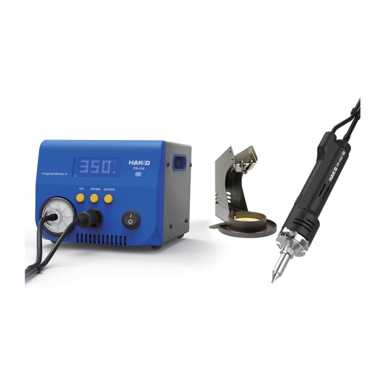
Page 2: Packing List And Part Names
1. PACKING LIST AND PART NAMES Please check to make sure that all items listed below are included in the package. HAKKO FR-410 Desoldering station HAKKO FH-410 Handpiece holder HAKKO FR-4104 Desoldering Handpiece (with Cleaning sponge) (with N61-05 ø1.0mm [0.04 in] nozzle) -
Page 3: Warnings, Cautions And Notes
● Use only genuine HAKKO replacement parts. ● Do not allow the HAKKO FR-410 to become wet, or use it when hands are wet. ● Be sure to hold the plug when inserting or removing the handpiece and power cords. -
Page 4: Initial Setup
4. INITIAL SETUP A. Handpiece holder Loosen the adjusting screws to change the angle of the handpiece receptacle as you like, then tighten the screws. CAUTION Increasing the angle of the handpiece receptacle will cause an increase in the handpiece temperature. ●... -
Page 5: Operation
To disconnect, pull the plug 2. Connect the plug from the HAKKO FR-4104 from the receptacle while to the receptacle on the HAKKO FR-410. pressing down the tab on the plug. CAUTION Connect the plug to the receptacle, aligning the tab on the plug with the opening on the receptacle. - Page 6 PLE ASE WA I T Please wait for the heater to reach the set temperature. B. Making Changes to Settings ● Selecting the preset number The HAKKO FR-410 has a preset mode. 1. Press any of the three control buttons. 2. The preset selection screen appears.
- Page 7 3. Make your SELECTION moving the cursor UP or DOWN 4. Press the <ENT> button to by pressing the corresponding finalize your selection. buttons. PRESET1 660℉ PRESET1 660℉ PRESET2 750℉ PRESET2 750℉ PRESET3 840℉ PRESET3 840℉ <↑> <↓> <ENT> <↑> <↓>...
- Page 8 ● Set Temp CAUTION The temperature range is from 620 to 850℉. (330 to 450℃) ● If you enter a value outside the temperature setting range, the display returns to the hundreds digit, and you have to enter a correct value. 1.
- Page 9 ● Offset Temp Example:If the measured temperature is 705℉ and set temperature is 700℉, the difference is -5℉. (need to decrease by 5℉) So, enter the figure which 5 is deducted from present offset value. 1. Move the cursor to select “Offset Temp”. After selecting, press <ENT>. S e t T e m p 680゚...
- Page 10 ● Vacuum Check During suction, the gauge indicating sucking status is shown at the lower side of the screen. C H K Suction gauge Sign of clogging When “CHK” appears and you notice that the sucking force is weakening, perform “Vacuum Check.” 1.
- Page 11 ● Preset Temp CAUTION The temperature range is from 620 to 850℉. (330 to 450℃) ● If you enter a value outside the temperature setting range, the display returns to the hundreds digit, and you have to enter a correct value. 1.
- Page 12 ● Preset ID CAUTION As a preset ID, 1 to 8 characters can be used. Usable characters are “A-Z,” “0-9,” and space (“ ”). Entering a space makes your entry terminated. Any character(s) that follows the space is deleted. 1. Move the cursor to select “Preset ID”. After selecting, press <ENT>. V a c u u m C h e c k P r e s e t T e m p...
- Page 13 ● LCD Contrast To make the screen display easy to see, adjust contrast. 1. Move the cursor to select “LCD Contrast”. After selecting, press <ENT>. P r e s e t T e m p P r e s e t L C D C o n t r a s t <↑>...
-
Page 14: Parameter Setting
6. PARAMETER SETTING ● PARAMETER SETTINGS Press and hold any one of the three control buttons, and turn on the power switch to display the parameter setting screen. The following parameters can be set: Parameter name Value Initial value Press and hold any one of ℉* Temp Mode ℃... - Page 15 ● Temp Mode The displayed temperature can be switched between Celsius and Fahrenheit. 1. Move the cursor to select “Temp Mode”. ゚ F T e m p M o d e After selecting, press <ENT>. S h u t O f f S e t O F F V a c u u m M o d e...
- Page 16 ● ShutOff Set 4. When setting “Shut Off” to “ON,” S h u t O f f S e t the area for “Timer” flashes. S h u t O f f T i m e r <↑> <↓> <ENT> 5. Press the <↑>...
- Page 17 ● Vacuum Mode Select whether you manually operate the desoldering pump or use the timer function. Normal:Solder is sucked only when you are pulling the trigger. Timer:Even after you release the trigger, sucking continues for the specified period of time. * Set time in “Vacuum Time.”...
- Page 18 ● Auto Sleep Select whether you will activate the auto sleep function. When the auto sleep function is set to on and no operation is performed for constant time after the iron is set in the iron holder, the auto sleep function will be enabled. * Set temp in “Sleep temp”.
- Page 19 ● Sleep Temp Sets the auto sleep temperature. 1. Move the cursor to select “Sleep Temp”. After selecting, press <ENT>. V a c u u mM o d e A u t o S l e e p 2. Entering from hundreds to units digit. S l e e p T e m p 390゚...
- Page 20 ● Error Alarm In the buzzer sound setting mode, which sets whether to sound the buzzer when a error occurs. 1. Move the cursor to select “Error Alarm”. 390゚ F S l e e p T e m p After selecting, press <ENT>. L o w Te m p 270゚...
- Page 21 ● Pass. Lock When enabling this function, you must enter a correct password to change a setting. The options are as follows: Lock : All setting changes require a password entry. Partial : Selection of whether or not to enter a password when changing set temperature, preset selection, and offset temperature.
- Page 22 ● Initial Reset Initial Reset allows the factory default settings to be restored. 1. Move the cursor to select “Initial Reset”. R e a d y A l a r m After selecting, press <ENT>. P a s s . L o c k I n i t i a l R e s e t...
-
Page 23: Maintenance
7. MAINTENANCE Properly maintained, the HAKKO FR-410 desoldering tool should provide years of good service. Efficient desoldering depends upon the temperature, nozzle selection, and proper routine maintenance. Perform the following service procedures as dictated by the conditions of the station's usage. - Page 24 Nozzle Maintenance CAUTION The desoldering tool may be extremely hot. During maintenance, please work carefully. 1. Inspect and clean the nozzle ● Turn the power switch ON and let the nozzle Cleaning with the nozzle cleaning pin The cleaning pin passes heat up.
- Page 25 2. Disassemble the heating element. Remove the enclosure pipe using the included nozzle wrench. CAUTION The enclosure pipe is held to the nozzle The heating element is changing tool by very hot during operation. pressing this part from both sides. Heating Enclosure pipe (The nozzle is not Element held to the nozzle changing tool. Be careful when removing them.) Nozzle 3. Clean out the tube in the heating Scrape away all oxidation from the tube in the heating element until the cleaning pin passes cleanly through element with the provided cleaning...
- Page 26 Replacing the heating element (heating core) CAUTION Except the case especially indicated, always turn the power switch OFF and disconnect the power plug before performing any maintenance procedure. 1. Remove the enclosure pipe, nozzle, and unplug the cord. 2. Remove the screws 1 , 2 securing Joint cover the joint cover to the heating element.
- Page 27 Maintenance of the pump head ● Remove the cover When performing maintenance on the pump head, remove the screws holding the cover and take the cover off. Pump head ● Cleaning the pump head 1. Remove the valve and valve guard and remove any attached flux. CAUTION Pump head disassembly •...
-
Page 28: Checking Procedure
8. CHECKING PROCEDURE WARNING Unless otherwise directed, carry out these procedures with the power switch OFF and the power UNPLUGGED. 1. Check for a broken heater or sensor ■ Check for a broken heater or sensor Measure the resistance across this position. Verify the electrical integrity of the heater and sensor. - Page 29 Checking the connection cord for breakage ■ Checking the connection cord for breakage 1. Unplug the connection cord from the station. 2. Disassemble the heating element. {Please refer to [Replacing the heating element (heating core)]} Pin contact 3. Measure the resistance values between the Socket connector and the lead wires at the socket as ①...
-
Page 30: Error Messages
9. ERROR MESSAGE When there is the possibility that a failure has occurred in the ● Sens Error sensor or heater (including the sensor circuit), "Sens Error" is displayed and the power is shut down. "Grip Error" will be displayed if the connector cord is not attached ●... -
Page 31: Trouble Shooting Guide
10. TROUBLE SHOOTING GUIDE WARNING Before checking the inside of the HAKKO FR-410 or replacing parts, be sure to disconnect the power plug. Failure to do so may result in electric shock. CHECK Is the power supply cable or connection plug disconnected? ●... -
Page 32: Parts List
11. PARTS LIST ⑨ Pump assembly ⑦ ③ ② ⑤ ⑪ ① ⑫ ⑬ ⑩ ① ⑧ ⑧ ⑪ ⑫ ⑤ ⑥ ③ ② ④ ⑦ ⑨ ⑳ ⑲ ⑱ ⑯ ⑮ ⑭ ⑰... - Page 33 ● HAKKO FR-410 Item No. Part No. Specifications Part Name 2 pcs. A1013 Diaphragm 2 pcs. A1014 Valve plate B1050 Pump head B1053 Balance weight B1056 Fixing plate B1057 Ring for bearing 2 pcs. B1059 Exhaust filter B1312 Crank B1313 Filter retaining pin B2060 Crank shaft...
- Page 34 ● HAKKO FR-4104 Part No. Part Name Specifications FR4104-81 HAKKO FR-4104 Straight type ● HAKKO FR-4104 parts Item No. Part No. Part Name Specifications B1915 Filter holder A1030 Spring filter 10 qty B1916 Filter pipe A5044 Ceramic paper filter (L) 10 qty 1 - 4 B2517...
-
Page 35: Wiring Diagram
12. WIRING DIAGRAM Power Inlet switch... - Page 36 NOZZLE STYLES N61-01 N61-02 N61-03 N61-04 N61-05 N61-06 N61-07 N61-08 N61-09 N61-10 N61-11 N61-12 (0.43) (0.43) N61-13 N61-14 N61-15 (0.04) (0.43) (0.43) (0.11) N61-16 N61-17 (0.04) (0.11) 99 Washington Street Melrose, MA 02176 Phone 781-665-1400 Toll Free 1-800-517-8431 Visit us at www.TestEquipmentDepot.com 2019.1 ©...
Need help?
Do you have a question about the FR-410 and is the answer not in the manual?
Questions and answers