Table of Contents
Advertisement
Quick Links
Brief Description / Applications
• Suction Pressure Controller and/or High Pressure Controller,
configurable for:
- Standard Compressors
- Compressors with CRII-System Control Stages
- Condensation High Pressure Control
• For up to 8 Suction Pressure Stages respective High Pressure Stages usable
• For use as a single controller or in a network
• Direct connection of up to 64 Cold Storage Controllers,
Data Exchange for Energy Optimization
• 4 Sensor-, 2 Pressure Transmitter- , 4 Digital Inputs,
5 Relay Outputs (2 Relays, 3 SSR-Relays), Analogue Output
• Capable of handling up to 4 additional stages.
(When used in conjunction with Expansion Module BMR 3002).
• For Single- and Multi-Stage Loads
• Peak Load Limitation, Suction Pressure Shifting
• Automatic Stage Sequencing
• Fixed or Autoadaptive Delay Times for Switching Frequency Optimization
• Capturing of Machine Feedback Signals and Plant Errors
• Analogue Output for P/PI-Control
• In-/Outputs configurable
• Manual Operation of all Machines
• Night Operation via internal clock
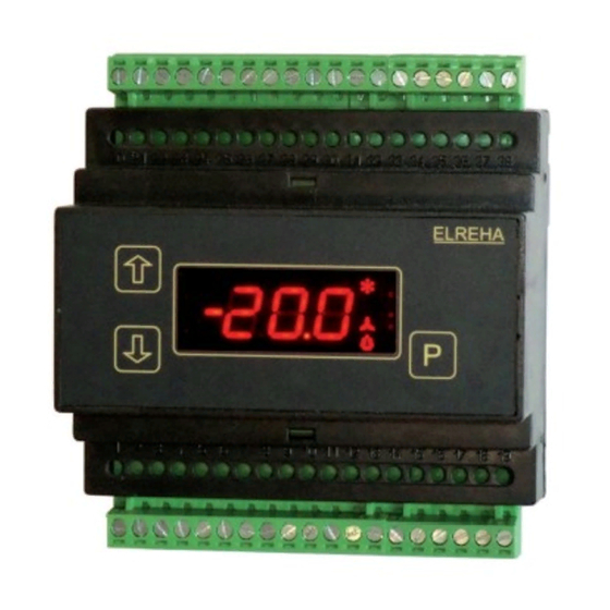
Operating / Operating Elements
EVP
increase
1
2
values
decrease
values
The displayed setpoint
is active
The current states of the Digital Inputs, the Relay Outputs and the Data
Transmission can be read on the Actual Values Page at L98 and L99.
Convenient 3 key control for all functions clearly appear on a 7 segment LED
display. 4 symbols to the right indicate active control function(s). (Relay status
is indicated separately on „Actual Page").
Programming
The MSR eco parameters are simple to access, view and change. During
normal operation, or if no key is pressed for at least 3 minutes, the MSR eco
will display the following:
1st priority: current failure display (blinking)
2nd priority: operation status display (ex. „oFF")
3rd priority: selected „permanent parameter" display
Selecting and Changing of Parameters
Key
Action
P (> 2 sec.) ....Page name will be displayed
.................Select desired page
P . .................Enter the page
.................Select parameter
P . .................Prepare programming. Enter access code if necessary
.................Change value.
If you hold the key, the values change continuously
P . .................Confirm programming
P (> 2 sec.) ....Page name will be displayed again
Access Protection
All adjustable parameters/set-points are protected by an access code.
They are divided into 3 groups or levels with 3 operator codes.
An access code will be required to change an adjustable parameter, (see
parameter listing). To change an adjustable parameter that requires an access
code, begin by pressing the „P" key.:
(00
The screen will display C00, prompting the user for access
code entry.
The Access Codes are divided into 3 access levels, (OEM, Technician, and
Customer Codes).
- OEM Code „oem": Month + Hour + 20
The OEM Code grants access to all adjustable parameters on the
device.
- Technician Code „tec" : 88
The Technician Code grants access only to „Technician" and „Customer"
assigned adjustable parameters.
- Customer Code „---" : no access code required.
The Customer Code grants access only to „Customer" assigned
adjustable parameters.
If no key has been pressed for 3 minutes, the operator code must be
re-entered.
LED blinking = Alarm
3
4
P
ELREHA
programming key
ELEKTRONISCHE REGELUNGEN GMBH
Technical Manual
Stage Controller
MSR
Parameter Pages
(L)
(r)
(d)
(P)
(A)
(h)
Please note Safety Instructions
on page 10 !
Attention
5311437-03/02
2018-06-25, tkd/jr
from Software Vers. 2.04
3140
eco
Some functions may not be available on devices
with older software versions.
P
> 2 sec.
P
L01
P
r01
P
d01
P
P10
P
A01
P
h01
/01
e
1st. Parameter
on the
Actual
Values
Page
Setpoint
Page
Suction
Pressure
Setpoint
Page
High
Pressure
Mode
Page
Address
Page
Assign-
ment
Page
Advertisement
Table of Contents

Related Manuals for ELREHA MSR eco 3140


Summary of Contents for ELREHA MSR eco 3140
- Page 1 • Fixed or Autoadaptive Delay Times for Switching Frequency Optimization • Capturing of Machine Feedback Signals and Plant Errors • Analogue Output for P/PI-Control Some functions may not be available on devices • In-/Outputs configurable with older software versions. • Manual Operation of all Machines • Night Operation via internal clock Operating / Operating Elements increase LED blinking = Alarm values decrease values ELREHA programming key The displayed setpoint is active The current states of the Digital Inputs, the Relay Outputs and the Data Transmission can be read on the Actual Values Page at L98 and L99. Convenient 3 key control for all functions clearly appear on a 7 segment LED display. 4 symbols to the right indicate active control function(s). (Relay status is indicated separately on „Actual Page“). Parameter Pages Programming The MSR eco parameters are simple to access, view and change. During > 2 sec. 1st. Parameter normal operation, or if no key is pressed for at least 3 minutes, the MSR eco...
-
Page 2: System Overview
Page 2 Technical Manual Stage Controller MSR eco 3140 MSR eco System Overview The MSR eco is designed to provide complete control for refrigeration systems with up to 4 respective 8 stages, while serving as a central unit for up to 64 cold storage controllers. When used in conjunction with front end devices such as the SMZ-5140 or Web-Gateway, the MSR eco becomes fully capable of control from a remote location, as well as message communication, (see example below): compound (+ 4 stages) (4 stages) 2x Pressure Transmitters 4x Temperature Sensors BMR 3002 Any Receiver : Controller Controller Controller e.g. Service Technician RS-485 (Line) Error Messages as Email Analog- Modem MSR eco 3140 SMZ 5140 Cold Storage Controller Cold Storage Controller Cold Storage Controller Cold Storage Controller Data Management with Cold Storage 'CV-Scheduler' locally Controller Cold Storage... -
Page 3: Configuration Concept
Technical Manual Stage Controller MSR eco 3140 Page 3 Error Messages / Error Memory / Error Codes Display of actual values and states If a failure occurs, parameter L20 will display a flashing error code, (see below Error Code Definition All actual values are shown on the "Actual Values List for reference). If multiple errors occur, the UP/DOWN arrow keys can be used to scroll through the Page" ((l)). error codes on the device display. The device is designed to always store the last 15 error messages, (including date and time of each occurrence), and can be accessed via data interface. Display of Temperatures and Pressures "L01"-"L04": ---- ..no error „Actual Values Page“ Displays actual current hrd ..hardware failure temperature for sensors 1-4 (-99.9...+100 C). Adr ..network address assigned more than once up to "L05": A00 ..communication error with controller at address 0 A63 ..communication error with controller at address 63 Displays actual current temperature converted from up to... - Page 4 Page 4 Technical Manual Stage Controller MSR eco 3140 Parameter Pages Actual Values Page (L) Param nA Eb Note range L01 ..X ..3,2 ...Actual temperature value of sensor 1 ....................-99,9...+100,0°C up to ......(can be corrected ±10K, the function is defined in the Assignment Page) L04 ..X ..3,2 ...Actual temperature value of sensor 4 ..................-99,9...+100,0°C L05 ..X ..3,2 ...Actual temperature value of input 5 (calculated from L15, pressure transmitter 1) ....-99,9...+100,0°C L06 ..X ..3,2 ...Actual temperature value of input 6 (calculated from L16, pressure transmitter 2) ....-99,9...+100,0°C L10 ..X . .. 3,2,1 . .Actual value SP / HP, poss. alternating display, cooling symbol SP, fan symbol HP ....-99,9...+100,0°C L15 ..X ...
- Page 5 Technical Manual Stage Controller MSR eco 3140 Page 5 Address Page (A) Param SubPar. Co Level Note Range ....tec ..3, 2 ..Address of the 1st. connected controller A00 d01 ..tec ..3, 2 ..Type of the connected controller .......- - - = no controller ..- - - ..- - - ..- - - ....- - - connected E30 = EVP 1130 E40 = EVP 1140 E50 = EVP 3150 E60 = EVP 3160 E67 = EVP 3167 E68 = EVP 3168 E70 = EVP 3170 t30 = TKP 3130 t40 = TKP 3140 t50 = TKP 3150 d02 ..tec ..3, 2 ..The connected controller acts on the ....0 = no effect....0 ....0....0 ....0 suction pressure shifting with: 1=limit.temperature 2=limit.temperature...
- Page 6 Page 6 Technical Manual Stage Controller MSR eco 3140 Setpoint Page Suction Pressure (r) Param Co Level Note Range Notice r01 ..--- ..3, 2, 1 ..Setpoint 1 (day) ..............-99,9...+100,0°C ..-10,0°C ..-10,0°C ..-10,0°C ..-10,0°C r02 ..--- ..3, 2, 1 ..Setpoint 2 (night) ..............-99,9...+100,0°C ..-10,0°C ..-10,0°C ..-10,0°C ..-10,0°C If this point is ON while displaying a r03 ..--- ..3, 2, 1 ..Setpoint maximum ..............-99,9...+100,0°C ..0,0°C ..10,0°C ..10,0°C ..10,0°C parameter number, this parameter r04 ..--- ..3, 2, 1 ..Hysteresis ................0,1...20,0K....2.0 K ..2.0 K ... 2.0 K ....2.0 K is active at present.
- Page 7 Technical Manual Stage Controller MSR eco 3140 Page 7 Setpoint Page High Pressure (d) Param Co Level Note Range d01 ..--- ..3, 2, 1 ..Setpoint of the first stage to switch on respective ....-99,9...+100,0°C ..35,0°C..35,0°C ..35,0°C ..35,0°C the last stage to switch off d02 ..--- ..3, 2, 1 ..Setpoint 2 ................-99,9...+100,0°C ..35,0°C..35,0°C ..35,0°C ..35,0°C d03 ..--- ..3, 2, 1 ..Setpoint 3 ................-99,9...+100,0°C ..35,0°C..35,0°C ..35,0°C ..35,0°C d04 ..
- Page 8 Page 8 Technical Manual Stage Controller MSR eco 3140 Assignment Page (h) Param Co Ebene Bedeutung Bereich h01 ..tec ... 3, 2 ..Function of Relay 1 ......--- = switched off, on= continuously, ......alA..l1 ...l1 .... l1 alA = Warning/Alarm, alA = Warnung/Alarm, SuA = Warning Suction Superheat L1 =SP-Stage 1, l2 =SP-Stage 2, L3=SP-Stage 3, L4 =SP-Stage 4, L5 =SP-Stage 5, l6=SP-Stage 6, L7 =SP-Stage 7, L8 =SP-Stage 8, K1=HP-Stage 1, K2 =HP-Stage 2, K3 =HP-Stage 3, K4=HP-Stage 4 K5 =HP-Stage 5, K6 =HP-Stage 6, K7=HP-Stage 7, K8 =HP-Stage 8 h02 ..tec .
- Page 9 35 36 MSR eco ELREHA 16 17 25 26 27 Pressure Signal out 4-20mA Transmitter 1 + Supply Voltage Pressure Transmitter 2 Signal out 4-20mA + Supply Voltage MSR eco 3140 Network relay relay relay (line) (SSR (SSR) 25 26 27 29 30 32 33 34 36 37 25 26 27...
- Page 10 Page 10 Technical Manual Stage Controller MSR eco 3140 CONNECTION INFORMATION & SAFETY INSTRUCTIONS The following conditions will result in an „Assignment Error“: Product warranty does not cover damage caused by failure Notice to comply with these operating instructions! Nor will ELREHA be held liable for any personal injury or damage to property - Exceeding 8HP stages or 8SP stages assigned. Notice - If the SP control sensor, HP control sensor, outdoor temperature caused by improper handling or failure to observe the savety sensor, or the suction tube temperature sensor are selected more instructions and recommendations contained in this or any than once. other ELREHA supplied document related to this product! - If no HP or SP control sensor has been selected. This manual contains additional safety instructions throughout - If relay functions 6-9 are assigned without the BMR being selected. the functional description. Please pay close attention to these - If the SPcontrol sensor is selected without defining the SP stages or SP analogue output. instruction! - If the HP control sensor is selected without defining the HP stages or HP analogue output.
- Page 11 Technical Manual Stage Controller MSR eco 3140 Page 11 Functional Description Input Signals of the Controller Base Load Change / Switching Frequency Opt. Base Load Change with Switching Frequency The input signals come from a 2-wire pressure If a plant is laid out correctly, then not all fans and Optimization at Backrun transmitter with a 4-20 mA signal or one of the four compressors should run continuously. When Due to the special requirements of the control de- (4) temperature probes. The source can be selected using normal stage controllers, some motors bear pending on the basic stage, the Switching at h21...h26 (Assignment page).
- Page 12 Page 12 Technical Manual Stage Controller MSR eco 3140 SDS - Machines with Feedback (SP, Motor 1-4) Operating Mode of the Motors (Manual/Auto) To detect the real state of a machine, the safety chain Each motor can be set to manual „ON/OFF“ operation Suction Pressure Optimization by can be checked using a digital input, which has a via ‚r61-r68‘ for SP, and ‚d61-d68‘ for HP. Setpoint Shifting with Cold Storage feedback function, (h31...h34). Default „ON/OFF“ operation is set to „Auto“. The controller switches a machine on and waits for a Controllers feedback signal while power is being applied to the Second Setpoint (Ex. Night Operation) digital input. If no feedback is detected, the machine Alternate setpoints can be established for energy will be switched off and a different machine will be Cold Storage Controllers with EEx-Valves:...
-
Page 13: Analogue Output
Technical Manual Stage Controller MSR eco 3140 Page 13 Analogue Output Digital Inputs Real Time Clock / Time Synchronization / Night Mode With the Digital Inputs DI1...DI4 (for mains voltage) The analogue output can be used for regulation a number of tasks can be triggered which can be set purposes or forwarding of the actual value. T he signal The built-in real time clock has a buffer for max. 10 on the Assignment Page (h). is available as a DC-Voltage (010) or a DC-Current- If the input is not required, it should be switched off. days without mains voltage. Date and time can be Signal (420), set by "h40" (Assignment Page). Whether the digital input reacts on voltage, (Active), set by "P80"..."P85" (Mode Page). Parameter "L96" (Actual Values Page) shows the or on no voltage, (Passive), is dependent upon the By default, a GMT +01:00 is set (P71 = 60 min.), current output signal as a %-part of the selected selected task: which is standard for the Central European Area. - Page 14 Page 14 Technical Manual Stage Controller MSR eco 3140 Networking of controllers via E-LINK The MSR eco can be networked together with The data transmission rate is factory set to "96" Configuration / Service via PC other ELREHA control devices via an RS-485-2- (9600 Baud) and can also be set manually ("P89", The controller can be linked to a PC via its RS-485 wire databus, which enables up to 78 controllers Mode Page). interface. By using the PC-software „Coolvision- to communicate. For communication, the E-LINK If the MSR eco is not connected to a network, these MES“, parameters can be changed, they can be transmission protocol is used. parameters are of no importance. saved to the hard disk (download) and can be sent Each controller in a network has its individual to the controllers (upload).
- Page 15 Technical Manual Stage Controller MSR eco 3140 Page 15 Configuration examples for up to 4 suction pressure stages This table gives you an overview of the parameters which must be set for specific plant structures. Application CRII Other Compressor Compressor CR II Compressor 2-cyl. Alarm Motor 1 CRII valve CR (St.1) 1.1 (St.2) 2-cyl. 1x1 stages Alarm Motor 2 Motor 1 CRII valve (Stage3) CR (St.1) 1.1 (St.2) 2-cyl. 2x1 stages Alarm Motor 3 Motor 2 Motor 1...
-
Page 16: Ec Declaration Of Conformity
Following standards were consulted for the conformity testing to meet the requirements of EMC and Low Voltage Guidelines: EN 55011:2016+A1:2017, EN 61010-1:2010, EN 61326-1:2013 CE marking of year: 2018 This statement is made for the manufacturer / importer ELREHA Elektronische Regelungen GmbH Werner Roemer, Technical Director D-68766 Hockenheim Hockenheim 2018-06-26 www.elreha.de...
Need help?
Do you have a question about the MSR eco 3140 and is the answer not in the manual?
Questions and answers