Table of Contents
Advertisement
Quick Links
Advertisement
Table of Contents

Related Manuals for dixell XC642C


Summary of Contents for dixell XC642C
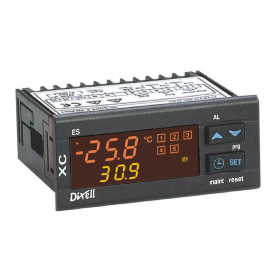
- Page 1 Compressor racks controller XC642C Operating manual...
-
Page 2: Table Of Contents
THERMOSTAT FOR LIQUID INJECTION ______________________________________ 13 TYPE OF REGULATION ___________________________________________________ 13 15.1 NEUTRAL ZONE ________________________________________________________________ 13 15.2 PROPORTIONAL BAND __________________________________________________________ 14 MOUNTING & INSTALLATION ______________________________________________ 15 ELECTRICAL CONNECTIONS ______________________________________________ 15 17.1 Probes connection_______________________________________________________________ 16 1592001330 XC642C GB r1.0 07.06.2004.doc rel. 1.0 Pa. 2 / 21... -
Page 3: General Warning
Fit the probe where it is not accessible by the End User. The instrument must not be opened. • In case of failure or faulty operation send the instrument back to the distributor or to “Dixell S.p.a.” (see • address) with a detailed description of the fault. -
Page 4: How To Select The Gas Type
NOTE: the set value is stored even when the procedure is exited by waiting the time-out to expire. 3.2 HOW TO SET THE RANGE OF THE PRESSURE PROBES If a instrument with the following part number is used: XC642C – xxxxF, it is pre-set to work with pressure probe with the following range:... -
Page 5: User Interface
To lock and unlock the keyboard. n n n n SET + To enter the programming mode. o o o o SET + To exit the programming mode. 1592001330 XC642C GB r1.0 07.06.2004.doc rel. 1.0 Pa. 5 / 21... -
Page 6: Icons
To memorise the new value and pass to the fan set point push the SET key. To change its value push the o o or n n within 30s. To exit: push the SET key or wait for 30 without pressing any keys. 1592001330 XC642C GB r1.0 07.06.2004.doc rel. 1.0 Pa. 6 / 21... -
Page 7: Parameters Programming
“oFF” label if the output is disabled for a maintenance section. With compressor with more steps all the LED’s linked to the compressor and the valves are switched on.. Select the output by pressing the UP or DOWN key. 1592001330 XC642C GB r1.0 07.06.2004.doc rel. 1.0 Pa. 7 / 21... -
Page 8: Output Disabled Signalling
To see the alarm duration and push the SET key. o o o o or SET By pushing again the key the next alarm is displayed. Alarms erasing. Enter the Alarm Menu. 1592001330 XC642C GB r1.0 07.06.2004.doc rel. 1.0 Pa. 8 / 21... -
Page 9: Use Of The Programming "Hot Key
HACCP menu. 11.2 TO UNLOCK THE KEYBOARD Keep the o o and n n keys pressed together for more than 3s till the “POn” flashing message appears. 1592001330 XC642C GB r1.0 07.06.2004.doc rel. 1.0 Pa. 9 / 21... -
Page 10: List Of Parameters
CL: the digital input is activated by closing the contact. Configurable digital input polarity functions (terminals 3 - 4) 1592001330 XC642C GB r1.0 07.06.2004.doc rel. 1.0 Pa. 10 / 21... -
Page 11: Display And Measurement Unit
(possibly after the tAo delay time). tAo: Low and High pressure (temperature) alarms delay– compressor section: (0÷255 min) time interval between the detection of a pressure (temperature) alarm condition and alarm signalling. 1592001330 XC642C GB r1.0 07.06.2004.doc rel. 1.0 Pa. 11 / 21... -
Page 12: Other
Valve 2 (50%) Valve 3 (75%) Relay (15-17) Relay (16-19) Relay (18-21) Relay (20-22) CLOSED OPEN CLOSED CLOSED CLOSED CLOSED OPEN CLOSED CLOSED CLOSED CLOSED OPEN 100% CLOSED CLOSED CLOSED CLOSED 1592001330 XC642C GB r1.0 07.06.2004.doc rel. 1.0 Pa. 12 / 21... -
Page 13: Thermostat For Liquid Injection
Relay valve 1 (66%) 100% Pression Compressor at 100% Set + (Pbd/2) Neutral Zone Time Set - (Pbd/2) Loads state Compressor disabled oA1(Compressor) On oA2(33%) On oA3(66%) Delay evolution Time Time 1592001330 XC642C GB r1.0 07.06.2004.doc rel. 1.0 Pa. 13 / 21... -
Page 14: Proportional Band
Relay 1 - Compressor Relay valve 1 (25%) Relay valve 1 (50%) Relay valve 1 (75%) 100% COMPRESSOR AT 100% Set+Pbd/2 Set+Pbd/4 Set-Pbd/4 Set-Pbd/2 ALL LOADS ARE ACTIVE oA1(Compressor) oA2(25%) oA3(50%) oA4(75%) 1592001330 XC642C GB r1.0 07.06.2004.doc rel. 1.0 Pa. 14 / 21... -
Page 15: Mounting & Installation
Keep the probe and the digital input wires separate from the power cable. Do not exceed the maximum rating current for each relay, check technical data and if the load is bigger, use filtered contactors. 1592001330 XC642C GB r1.0 07.06.2004.doc rel. 1.0 Pa. 15 / 21... -
Page 16: Probes Connection
Second probe presence. dSEP Dynamic set point enabling Probe for analog output Probe for triac output When these parameters are set in wrong way an alarm message is generated: 1592001330 XC642C GB r1.0 07.06.2004.doc rel. 1.0 Pa. 16 / 21... - Page 17 (E.I. for lack of oil or overheating, etc,) the corresponding load is turn off. Parameters ALIP: It establishes if the input is activated by closing (ALIP=cL) or by opening (ALIP=oP) the terminals. 1592001330 XC642C GB r1.0 07.06.2004.doc rel. 1.0 Pa. 17 / 21...
-
Page 18: Alarm Muting
When the input is disable: unchanged. hold pressed the Restart(DOWN)key for 3s or turn off and on the instrument.. The compressors restarts working according to the working algorithm. 1592001330 XC642C GB r1.0 07.06.2004.doc rel. 1.0 Pa. 18 / 21... - Page 19 A load has worked - signalling only Manually: reset the running hour of the compressor maintenance for the hour set in (see par.8 Running hours of loads) alarm the SEr parameter 1592001330 XC642C GB r1.0 07.06.2004.doc rel. 1.0 Pa. 19 / 21...
-
Page 20: Wiring Connections
/ dE rELP Pr2 Pressure displaying rEL / AbS > 0 ÷ 10.0 bar / 30.0 °C / 80 PSI Pr2 Proportional band or neutral zone width / 50 °F 1592001330 XC642C GB r1.0 07.06.2004.doc rel. 1.0 Pa. 20 / 21... - Page 21 Z.I. Via dell’Industria, 27 - 32010 Pieve d’Alpago (BL) ITALY tel. +39 - 0437 - 98 33 - fax +39 - 0437 - 98 93 13 http://www.dixell.com E-mail: dixell@dixell.com 1592001330 XC642C GB r1.0 07.06.2004.doc rel. 1.0 Pa. 21 / 21...
Need help?
Do you have a question about the XC642C and is the answer not in the manual?
Questions and answers