Table of Contents
Advertisement
AUMA Matic Positioner
Calibration Instruction
AUMA MATIC Compacts consist of motor controls, local controls and other control elements, which may be
required to operate an electric actuator
Scope
These instructions are intended to cover the AUMA MATIC compact in both the C and S configuration with an
AUMA positioner board. These instructions are for general startup and basic trouble shooting.
For calibration/setting of Standard Interface Board or Pulse Timer, refer to the appropriate instructions.
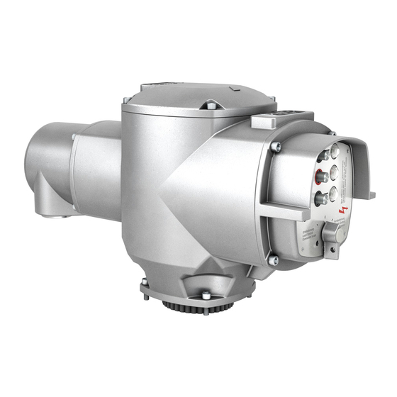
The positioner is usually supplied internally mounted in the AUMA MATIC Compact (Figure 1). These instructions
also apply if the positioner is remotely mounted. The positioner is programmable for several command and
internal feedback signals. Additionally, the choice of fail modes on loss of these signals can be chosen. Refer to
the programming section (Figure 4) for more information.
The Standard version of the positioner is supplied as a clockwise-actuator output on decreasing-command signal.
Consult the AUMA factory for information on other available configurations.
The convention of clockwise actuator output to close is used throughout this instruction.
General Description
The positioner is an electric controller, employing solid state circuitry, intended for regulating electric motor driven
actuators used on valves, dampers and other devices requiring accurate positioning control. Accurate positioning
is attained through the use of a precision position feedback potentiometer or current device (RWG current
transmitter). The controller drives the motor reversing starters which can be electromechanical (AUMA MATIC-C)
or solid state (AUMA MATIC-S). The controller utilizes a comparator circuit which senses the error between the
input command signal and the internal position feedback signal. The controller then energizes the motor
reversing starter control circuit to drive the actuator in the direction necessary to reduce the error signal to within
the customer set deadband.
Two modes of control are available. In the first mode the motor is continuously energized until the error between
the feedback signal and setpoint is zero. In the second mode (pulse mode) the motor is pulsed based on the
setting of a potentiometer, Time-on (P8), until the error is 25 percent or less. Then the Time-on is reduced by a
factor of 3 through the final 25 percent of error. The initial setting of "OFF" time remains constant. In the pulse
mode the initial "ON" and "OFF" times are field adjustable via the potentiometers P8 and P10.
Note: The AUMA MATIC with positioner generally incorporates a means of remote manual operation using
contact closure. This circuit, using the remote command board, is designed as a secondary input for
push buttons or relay contacts. It is not intended for "modulating" operation when an analog signal is not
available. An interface board is available for use in this case.
ISSUE 02/02
All information in this document is subject to change without notice.
Page 1 of 11
AUMA Actuators, Inc. USA
SE-SI-35-0007
Advertisement
Table of Contents

Subscribe to Our Youtube Channel
Summary of Contents for AUMA Matic Series
- Page 1 Scope These instructions are intended to cover the AUMA MATIC compact in both the C and S configuration with an AUMA positioner board. These instructions are for general startup and basic trouble shooting. For calibration/setting of Standard Interface Board or Pulse Timer, refer to the appropriate instructions.
- Page 2 • Connect field wiring according to wiring diagram supplied. If drawing is not available, contact the nearest AUMA office with the Sales Order or Serial Number located on the actuator nameplate. A replacement drawing will be provided. NOTE: ACTUATOR LIMIT SWITCHES MUST BE SET USING APPROPRIATE SETTING INSTRUCTIONS PRIOR TO PROCEEDING.
- Page 3 Also provided on the Logic Board are four solder links. When the soldered link is present on pads J1 and J3, the integral open and close lights on the Monitor Control board within the AUMA Matic will both be on in a intermediate valve position.
- Page 4 Turn control switch or operate push-button in either open or close direction. If actuator fails to operate, verify the following possible conditions. NOTE: 3Ø AUMA MATIC compacts incorporate a phase discriminator. If AUMA MATIC fails to respond to local and remote operation, reverse U1 and W1 at field terminals.
- Page 5 AUMA Matic Positioner Calibration Instruction AUMA Actuators, Inc. USA The AUMA Matic positioner incorporates the following features for field calibration and commissioning (Figure 3). ZERO (0/P3) This control adjustment calibrates the positioner to correspond to the lowest command signal. SPAN (max/P4) This control adjustment calibrates the positioner to the full 100 percent range of the command signal.
- Page 6 • The optional RWG 4-20ma feedback transmitter, if supplied, must be calibrated prior to positioner calibration. Refer to the AUMA SA or SG.1 Operation Instruction Manual for calibration instructions. NOTE: Verify proper limit switch setting prior to positioner calibration. Calibration Procedure...
- Page 7 AUMA Matic Positioner Calibration Instruction AUMA Actuators, Inc. USA Setting of the Sensitivity • Set selector switch at local controls (Figure 1, Page 2) to position REMOTE. • Input a random command signal E1. The sensitivity (∆E / dead band) is set to maximum value (2,5 %) in the factory.
- Page 8 AUMA Matic Positioner Calibration Instruction AUMA Actuators, Inc. USA Possible LED indication: Required setting in end position OPEN (refer to Figure 3) (refer to Figure 3) Turn potentiometer ”0” (P3) slightly clockwise until LEDs are not illuminated (V28 green) lights up.
- Page 9 AUMA Matic Positioner Calibration Instruction AUMA Actuators, Inc. USA Positioner adjustment for Split Range (See also example below) • Supply the specified minimum input signal (nominal value E1) for the positioner and check by measuring with Voltmeter at the measuring points MP3 and MP4 (Figure 5).
- Page 10 AUMA Matic Positioner Calibration Instruction AUMA Actuators, Inc. USA Condition Programming Function at Command Signal Feedback Loss of Signal E1 S1-7 S2-7 (Reference input E1) (Actual Value) E2 1 2 3 4 5 1 2 3 4 5 4-20 mA...
- Page 11 AUMA Matic Positioner Calibration Instruction AUMA Actuators, Inc. USA 1) Function at loss of signal E1 Fail as is Actuator stops immediately after loss of E1 and remains in this position Fail close Actuator runs to the closed position after loss of E1...
Need help?
Do you have a question about the Matic Series and is the answer not in the manual?
Questions and answers