Advertisement
Quick Links
OPERATOR'S MANUAL
INCLUDING: OPERATION, INSTALLATION & MAINTENANCE
READ THIS MANUAL CAREFULLY BEFORE INSTALLING,
It is the responsibility of the employer to place this information in the hands of the operator. Keep for future reference.
SERVICE KITS
Use only genuine ARO® replacement parts to assure compat-
ible pressure rating and longest service life.
SS-BQG550 for universal bracket replacement.
PNCV-1/2 for pneumatic controlled valve replacement.
637523 for Tubing kit replacement.
MODEL DESCRIPTION CHART
ARO StandardSolution
Application
D - Dewatering
Fluid
5 - Water
Type
01 - Pneumatic liquid
level control
PLC Control Option
B - No PLC
Metering Option
N - No metering
Industry
08 - Mining
Liquid Level
Sensor Version
V1 - Standard
V2 - Low level anti-
block
Installation Style
D – w/bracket for 2"
and 3" PRO and EXP
pumps
INGERSOLL RAND COMPANY LTD
209 NORTH MAIN STREET – BRYAN, OHIO 43506
(800) 495-0276 FAX (800) 892-6276
arozone.com
AUTOMATIC DEWATERING SYSTEM
OPERATING OR SERVICING THIS EQUIPMENT.
SC D 5 01 B N 08 - VX X
© 2015
CCN 47533490001
SCD501BN08-VXX
COMPONENTS INCLUDED WITH KIT
LLS-SC-VX
Liquid Level Sensor (LLS), Version 1 or 2
SS-BQG550
Universal Mounting Bracket
637523
Tubing Kit (includes 20m of 6mm tubing and two filters)
PNCV-1/2
Pneumatic Controlled Valve (PCV) Module Assembly
97999-7154
Operator's Manual
GENERAL DESCRIPTION
The ARO® Automatic Dewatering System (ADS) offers
automatic on/off controls of air operated diaphragm pumps.
The ADS has a Liquid Level Sensor (LLS) which produces a
pneumatic output signal as the fluid level in an unpressurized
vessel rises past a predetermined level and stops the signal as
the fluid level falls past a lower predetermined level.
This pneumatic signal actuates the Pneumatic Controlled Valve
(PCV) in order to open the air line and start the diaphragm
pump. The liquid level range can be set by changing the loca-
tion of the tail ends of the "High Level" and "Low Level" sensing
tubes.
RELEASED: 5-25-15
REVISED
(REV: B)
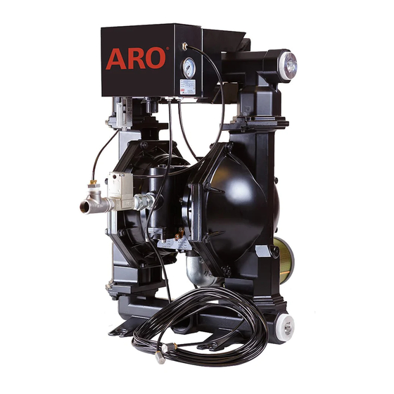
Figure 1
11-20-15
Advertisement

Related Manuals for ARO SCD501BN08-V Series


Summary of Contents for ARO SCD501BN08-V Series
- Page 1 It is the responsibility of the employer to place this information in the hands of the operator. Keep for future reference. SERVICE KITS Use only genuine ARO® replacement parts to assure compat- ible pressure rating and longest service life. SS-BQG550 for universal bracket replacement.
-
Page 2: Installation
Mount the LLS to the bracket using the M6 bolts and the making sure the vertical edge of the bracket is against the washers. See Figure 4. flat side of the manifold (where ARO logo is). See Figure 2. NOTICE NOTICE ... - Page 3 Repeat step 1 and connect the PCV to the air signal output- port of the LLS. Finish all of the above steps to complete the installation. NOTICE The PNCV-1/2 PCV Module is compatible with 2” and 3” ARO Air Signal pumps. An adaptor (not supplied) may be used for compat- Output Port ibility with smaller pumps.
- Page 4 Installation Sensing Tube Tube Filter (Included in 637523 Tubing kit) Figure 8 SS-BQG550 MOUNTING BRACKET COMPATIBILITY The mounting bracket (SS-BQG550) is compatible with the following ARO pumps: Pump Type Generic Model Number Notes 2” metallic EXP PX20X-XXX-XXX-X 2” metallic PRO 6662XX-XXX-C 2”...
-
Page 5: Troubleshooting
TROUBLESHOOTING Pump does not work when the liquid level rises above 10 Pump stops working when the liquid level falls to the open cm (4 inches) higher than the open end of the High Level end of the Low Level Sensing Tube. Sensing Tube. - Page 6 NOTES Page 6 of 8 SCD501BN08-VXX (en)
- Page 7 NOTES SCD501BN08-VXX (en) Page 7 of 8...
- Page 8 PN 97999-1754 Page 8 of 8 SCD501BN08-VXX (en)
Need help?
Do you have a question about the SCD501BN08-V Series and is the answer not in the manual?
Questions and answers