Table of Contents
Advertisement
How to Use This Manual
Acrobat provides various methods for navigating through a PDF document. The
recommended method of navigating this manual is through the use of the Bookmarks.
To browse using Bookmarks:
Show the Bookmarks list.
By default the manual will open with the Bookmarks list open on the left side of the
document. If you do not see the bookmarks list choose Window > Show Bookmarks to
open the list or click the Bookmarks tab to bring the list to the front of its group.
To expand the bookmark list
Bookmarks can be subordinate to other bookmarks in the list. If a bookmark has
subordinate bookmarks under it then it will have a plus sign next to it. To expand the book
mark list click the plus sign. After the list is expanded a minus sign will be displayed next
to the bookmark. To collapse the list click on the minus sign.
To jump to a topic using its bookmark
Click the bookmark's text in the list and the document will jump to the corresponding page
in the manual.
Additional Navigation Methods:
• To go to the next page, click the Next Page button in the navigation toolbar or status
bar, press the Right Arrow key, press Ctrl (Windows) or Option (Mac OS) and the Down
Arrow key, or choose Document > Next Page.
• To go to the previous page, click the Previous Page button in the navigation toolbar
or status bar, press the Left Arrow key, press Ctrl (Windows) or Option (Mac OS) and the
Up Arrow key, or choose Document > Previous Page.
• To move down one line, press the Down Arrow key.
• To move up one line, press the Up Arrow key.
• To move down one screenful, press Page Down or Return.
• To move up one screenful, press Page Up or Shift+Return.
• To go to the first page, click the First Page button in the navigation toolbar or status
bar, press the Home key, or choose Document > First Page.
• To go to the last page, click the Last Page button in the navigation toolbar or the
status bar, press the End key, or choose Document > Last Page.
Advertisement
Table of Contents

Subscribe to Our Youtube Channel
Summary of Contents for Edmunds Gages Trendsetter II
-
Page 1: How To Use This Manual
How to Use This Manual Acrobat provides various methods for navigating through a PDF document. The recommended method of navigating this manual is through the use of the Bookmarks. To browse using Bookmarks: Show the Bookmarks list. By default the manual will open with the Bookmarks list open on the left side of the document. - Page 2 rend-Setter II User’s Manual GAGES Edmunds...
-
Page 3: Table Of Contents
Table of Contents Preface Manual Revision History Trademark Information Introduction Summary & Features Document Conventions Anti-Static Precautions Glossary of Terms Quick Start Guide Programming Reference Guide System Description Number References Specifications Spare Parts Overall Unit Front Panel Rear Panel Rear Panel Pin Assignments Input/Output Pin Assignments RS-232C 2-10... - Page 4 Advanced Operation Signal Conditioning Module Setup A/E Module Setup Jumper Settings Gain Polarity Output Module Installation A/E Maintenance LVDT Module Setup Input Polarity Jumper Settings 4-10 Outputs 4-10 Inputs 4-12 Sum/Difference 4-14 Attenuation 4-16 Calibration A and B 4-17 Module Installation 4-18 External Device Communication 4-19...
- Page 5 Table of Figures Figure 2.1 - Overall Basic unit Figure 2.2 - Front Panel Figure 2.3 - Rear Panel Figure 2.4 - I/O Pins Figure 2.5 - I/O Connections Figure 2.6 - RS232C Pins 2-10 Figure 2.7 - LVDT Module 2-12 Figure 2.8 - A/E Module 2-14...
-
Page 6: Manual Revision History I
3/10/05 E8302 board Corrected I/O cable listed in Advanced Operation section to be #4550200, was #4550203 Update section 4.5, Auto Air Shutoff – 25 pin connector to Port “B” only Trademark Information “Trendsetter” is a registered trademark of Edmunds Gages... -
Page 7: Introduction
I/O accessory board is installed, Edmunds #5911013, sold separately. An RS- 232C connector allows output of gage results to a data collector. The Trendsetter II will operate at any supply line voltage between 100 VAC to 240 VAC at either 50 or 60 HZ. -
Page 8: Document Conventions
“OVER” = Alphanumeric Display 1.2 Anti-Static Precautions When working inside the Trendsetter II cabinet or handling signal conditioning modules use caution to protect against damage from static electricity. Use of an anti-static wrist band or other grounding procedures are recommended. -
Page 9: Glossary Of Terms
1.3 Glossary of Terms An A/E (Air to Electric) transducer converts changes in pneumatic pressure into an electrical signal. A part Check is an input or combination of inputs expressed with a gaging mode to exhibit a part characteristic. The Gain setting on the A/E signal conditioning module sets the amplification factor of an input signal to a usable value that can be interpreted by the readout device A Gage is a mechanical device used to measure part characteristics. - Page 10 In +PEAK (or -PEAK) modes the largest (or smallest) size reading since the last reset is displayed. Range is the full scale value of the bargraph display. An R & R is a statistical study performed on a gage to determine the gages repeatability and reproducibility.
-
Page 11: Quick Start Guide
1.4 Quick Start Guide The following steps must be taken to prepare the Trendsetter II for operation. 1) Unpack and setup the unit. • Rotate the front foot 90° from its shipping position. • For air gaging applications, rotate the rear foot 180° from its shipping position and install the filter regulator assembly. -
Page 12: Programming Reference Guide
Programming Reference Guide The following reference guide briefly outlines the functions of the programming buttons for the Trendsetter II. Figure 1.1... -
Page 13: System Description
System Description 2.0 Number References Component Edmunds Gages Number ® E8300 Basic Trendsetter II Unit (2) Channel LVDT Signal Conditioning Module E8302 (1) Channel A/E Signal Conditioning Module E8303 Power Cable 4550111 Air Filter/Regulator Assembly 5801302 Interface Cable 4550200 Printer Cable... -
Page 14: Spare Parts
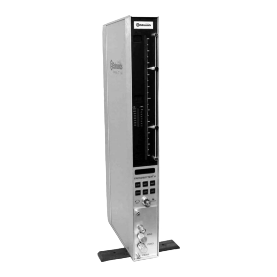
2.2 Recommended Spare Parts Below is a list of recommended spare parts for the Trendsetter II. These items may be ordered separately from Edmunds Gages, they are not included with the basic unit. Part Edmunds Gages P/N Qty. Basic Unit... - Page 15 2.3 Overall E8300Unit Figure 2.1 - Trendsetter II Basic Unit...
-
Page 16: Front Panel
2.4 Front Panel The Trendsetter II front panel consists of the following items: Bargraph display - The 10 inch, 101 point, three color LED bargraph display is the primary readout for the Trendsetter II. When over and under limits are programmed, the bargraph will change colors to visually indicate over (red), under (yellow), or good parts (green). -
Page 17: Figure 2.2 - Front Panel
Figure 2.2 - Front Panel... -
Page 18: Rear Panel
44 PSI Inlet - When the air to electric module is installed in the lower bay, an air hose fitting will extend out the 44 psi inlet port on the rear of the Trendsetter II. An air line is connected to this fitting and to the outlet side of the air filter/regulator assembly. -
Page 19: Figure 2.3 - Rear Panel
Figure 2.3 - Rear Panel... -
Page 20: Figure 2.4 - I/O Pins
2.6 Pin Assignments for Rear Panel connectors In/Out A, In/Out B (25 Pin Female DSUB) Figure 2.4 - I/O Pins Pin Number IN/OUT A Description IN/OUT B Description Analog Out 1 “ Analog Out 2 “ Analog Out 3 “ Analog Out 4 “... - Page 21 Typical IO Connections - Optional I/O Board #5911013 Required OUTPUT "SINKING" IO A/B IO A/B LOAD +24 VDC (+) LOAD GOOD RELAY CURRENT FLOW 0 VDC (-) 24VDC Power Suppl y OUTPUT "SOURCING" IO A/B IO A/B LOAD +24 VDC (+) GOOD RELAY CURRENT...
-
Page 22: Rs-232C
Figure 2.5 RS232C (9 Pin Female DSUB) Figure 2.6 - RS-232C Pins Trendsetter II Cable External Device ß----------------------------à Chassis Ground. Pin 1 = Chassis Ground. ß----------------------------à (TXD) Transmit. Pin 2 = Receive (RXD) ß----------------------------à (RXD) Receive. Pin 3 = Transmit (TXD) ß----------------------------à... -
Page 23: Jumper Settings
LVDTs that converts the outputs of the transducers into a conditioned signal for the main controller board. The module is mounted in the lower bay of the ® Trendsetter II polarity of inputs A and B must be setup using either switches on the original version of the board or jumpers on the current version of the circuit board. - Page 24 Figure 2.7 - E8302 (2) Channel LVDT Signal Conditioning Module 2-12...
-
Page 25: Gain
® of the Trendsetter II . The module is mounted in the lower bay of the Trendsetter II The A/E module also contains a ZERO adjustment knob and a MAG adjustment knob for initial input setup to accommodate the air tooling used.. - Page 26 Figure 2.8 - E8303 (1) Channel AE Signal Conditioning Module 2-14...
-
Page 27: Filter Regulator Assembly
Any unit supplied with an A/E signal conditioning module will also be supplied with a filter/regulator assembly. The assembly is mounted to the rear foot of the Trendsetter II. The regulator is factory preset to 44psi and requires a clean, dry air supply at 60psi min. -
Page 28: Basic Operation
Basic Operation 3.0 Set up and Operation Summary The following steps must be taken to prepare the Trendsetter II for operation. 1) Unpack and setup the unit. See "Unpacking & Setup" below. 2) Setup signal conditioning module jumpers and install module. See the "Advanced... -
Page 29: Unpacking & Setting Up
9) For air gaging applications only, connect a source of clean, dry air at 60 psi min to the air filter/regulator inlet. NOTE: The Trendsetter II regulator is factory set to 44psi. 10) Connect the gage tooling to be used to the signal conditioning module. For air gaging connect the air hose from the air plug, air ring, or air snap to the tooling port on the front of the A/E module. -
Page 30: Figure 3.1 - Base Feet
Front Mounting Foot Rear Mounting Bracket Figure 3.1 - Base Feet Figure 3.2 - Filter/Regulator Mounting... - Page 31 Figure 3.3 - Air Connections For Air Gaging Application Only...
- Page 32 A/E module. For electronic gaging connect the one or two LVDTs to inputs A and/or B on the front of the LVDT module. 12) Turn on the Trendsetter II by turning the power switches on the rear of the units to “ON”.
-
Page 33: Signal Conditioning Module Setup
3.2 Signal Conditioning Module Setup A/E Signal Conditioning Module, E8303 polarity of the input and the air amplification gain must be setup using jumpers on the module circuit board. The polarity of the input determines whether the input reads positive or negative as the air nozzles are closed off. The air amplification gain is set to low, medium, or high depending on the range to be used with the air tooling. -
Page 34: Programming
A brief explanation of the program guide follows: The top section of the programming guide list the scale, range, mode, and limits to be programmed in the Trendsetter II. The type of signal conditioning module to be used in the lower bay is also listed. -
Page 35: Output
Trendsetter II Setup Guide Customer: XYZ Company S.O.# 123456 SKG-12345 Scale Inch Inch Inch Inch Range (See note 1) Mode (See note 2) Limits - Over Under Signal Conditioning E8302 E8303 E8302 E8303 E8302 E8303 E8302 E8303 Accessories I/O Board (4110943-BM) - Page 36 Setting Scale, Range, Mode, and Limits Use the following procedure to program the Trendsetter II for a specific application: 1) Press IN/MM. The currently selected scale, “INCH” or “METRIC” will be displayed in the alphanumeric display. 2) Press IN/MM again while the display is flashing to select a different scale.
-
Page 37: Mode Descriptions
12) Press the Enter button to exit the limits setting mode. 13) The Trendsetter II is now programmed. See “Input Setup & Mastering” to continue preparing for operation of the unit. -
Page 38: Inputs Setup
3.4 Input Setup Setting A/E Mag and Zero for Air Gage If the gage tooling is an airplug or air ring using an A/E module use the following procedure to set zero and magnification using a set of max and min masters. 1) Press MODE until “LIVE RDG”... -
Page 39: Setting Lvdt Mag & Zero
Setting LVDT Mag and Zero Single Probe Setup If the gaging fixture uses only one LVDT probe use the following procedures to set the probe zero and magnification using a mean master or a set of max and min masters. Single Probe Setup Using a Mean Master 1) Turn the INPUT knob to the input that is to be setup , “A”... - Page 40 Single Probe Setup Using a Max and Min Master 1) Turn the input knob to the input that is to be setup , “A” or “B”. 2) The zero knob adjustment is a ten turn potentiometer. Prior to setting zero turn the zero knob for the input to be setup (A or B) to approximately the middle position, about five turns from the end stops.
- Page 41 Two Probe Setup If the gaging fixture uses two LVDT probes in the A+B mode, for instance to measure an O.D., use the following procedures to set the probe zero and magnification using a mean master or a set of max and min masters. Two Probes Setup Using a Mean Master 1) The ZERO knob adjustments are ten turn potentiometers.
- Page 42 Two Probes Setup Using a Max and Min Master 1) The ZERO knob adjustments are ten turn potentiometers. Prior to setting zero turn the zero knobs for inputs A and B to approximately the middle position, about five turns from the end stops. 2) Press MODE until “LIVE RDG”...
- Page 43 2) Mount the A and B probes in the balancing fixture. 3) Adjust each probe to its mechanical zero as observed on the Trendsetter II bargraph display. Then with the range switch set to desired application range, and the input switch set to A+B mode, rotate the micrometer head some convenient distance.
- Page 44 O.D. application the min master is used. 1) Place the master in the gage fixture. 2) Adjust the Trendsetter II display to zero. 3) Push the master in a direction which is parallel to the plane that the gage probes are ...
-
Page 45: Live Rdg Mode
TIR check is complete press HOLD. For example to check roundness of a hole: 1) Place the part on an air plug connected to the Trendsetter II 2) Press RESET. 3) Rotate the part through at least one revolution. - Page 46 HOLD. For example to check the maximum diameter of a hole: 1) Place the part in an air plug connected to the Trendsetter II 2) Press RESET. 3) Rotate the part through at least one revolution. 4) Read the -PEAK value from the alphanumeric display or the bargraph.
-
Page 47: Figure 4.1 - A/E Module, E8303
Advanced Operation 4.0 A/E Signal Conditioning Module Setup The E8303 Air/Electronic module converts pneumatic pressure from air gage tooling into a calibrated electrical signal. The module contains an air/electronic transducer assembly, three selectable fixed gains, a polarity reversal jumper, and an output pin selection jumper. -
Page 48: Figure 4.2 - Gain Jumper
A/E Jumper Settings Air Amplification (Gain) Jumper Range Air Amplification .010”/.2mm .005”/.1mm .002”/.05mm Medium .001”/.02mm Medium/High .0005”/.01mm High .0002”/.005mm High The gain jumper provides the following three fixed stages of amplification: Low - 1 x Medium - 3 x High - 9 x The low and medium positions of the gain pin header will allow calibration of most air tooling. -
Page 49: Figure 4.3 - Polarity Jumper
Polarity Jumper Increasing air pressure at the tooling will cause the readout to move upwards when the polarity jumper is in the (“+”) position. The opposite occurs with the jumper in the (“-”) position. This switch is used for setup changes between inside and outside diameter applications. - Page 50 Output Pin Selection Jumper The electronic signal from the A/E transducer may be output to another Trendsetter II or to an external device connected to the analog buss. The pin on which the signal is output, from 1 to 6, can be selected using the "A OUT" jumper. The "B OUT" jumper is not used on the E8303 module.
- Page 51 A/E Module Installation 1) Turn off the main power switch on the rear of the Trendsetter II and unplug the power cord. Power to the column must be turned off prior to installing or removing a signal conditioning module. 2) Ensure all jumpers are properly set for the application to be run. The polarity and gain jumpers must be set for every application.
- Page 52 Reinsert the mag needle valve and screw down until the point on the Trendsetter II scale comes back to the master point. Repeat the procedure on the zero knob. By only cleaning one needle at a time, the ga ge setting is not lost.
-
Page 53: Figure 4.5 - A/E Block
Figure 4.5 - A/E Block... -
Page 54: Figure 4.6 - Lvdt Module, E8302
The E8302 LVDT signal conditioning module is a two channel signal conditioning amplifier. The module plugs into the lower bay of the Trendsetter II and converts the outputs of the transducers into a useable format for the main controller board. - Page 55 Figure 4.6a - LVDT Module E8302, current version...
-
Page 56: Jumper Settings
Polarity The polarity of the input determines whether the input reads positive or negative as the probe tip is depressed. The bargraph will rise when the tip of the probe is pressed toward the body of the probe in the (+) setting. The polarity of input A and input B can be set independently. - Page 57 Input A Polarity Jumper Input B Polarity Jumper Figure 4.7a – Polarity Jumpers, current version 4-11...
-
Page 58: Outputs
LVDTs in a gage fixture and inputs C and D are bussed in from another Trendsetter II then the SUM OUT signal will be equal to A + B + C + D. This is a low level signal. -
Page 59: Inputs
Output Jumpers Input Jumpers Input Type Jumpers Figure 4.8 - Input/Output Jumpers 4-13... - Page 60 Input Pin Selection Jumpers If an auxiliary signal is to be bussed in from another Trendsetter II or external device the input pin assignment, from 1 to 6, must be set using jumpers CIN VAR, CIN FIX, DIN VAR, or DIN FIX.
- Page 61 Input Type Jumpers(J6, J7) If a signal from an air to electric module is to be bussed in as input C, variable magnification, jumper J6 must be set to "A". Set jumper J7 to "A" if the air to electric signal is bussed in as input D, variable magnification.
-
Page 62: Figure 4.9 - Sum/Difference Jumpers
A + B + (Results C & D) For example, consider a Trendsetter II with an E8302 module, two LVDT inputs connected to the A and B inputs and two external signal bussed in as C and D. If jumper J8 is set to "C+D"... - Page 63 "AB" then the display will show the value of input A + B + (C - D). As an other example consider a Trendsetter II with LVDTs A and B used to measure the diameter of a part with the "INPUT" selection knob set to AB to display the results of A + B.
-
Page 64: Figure 4.10 - Attenuation Jumpers
Attenuation Jumpers Jumpers J3, J4, and J10 allow the input attenuation to be set to 10x or 1x. For standard transducers the jumpers should be set to 1x. If long range transducers are to be use the jumpers should be set to 10x. See figure 4.10, obsolete board, or figure 4.10a, current revision of board, for jumper settings. - Page 65 J3, J4 Figure 4.10a - Attenuation Jumpers, current revision 4-19...
- Page 66 Cal A and Cal B Potentiometers These (20) turn pots set the primary magnification of the “A” or “B” amplifier. The pots affect the LVDT in the respective channel, and the respective channel output signal to the matrix switch. The gain range it .5x to 1.5x. These potentiometers are factory pre-set and do not normally require adjustment.
-
Page 67: Module Installation
LVDT Module Installation 1) Turn off the main power switch on the rear of the Trendsetter II and unplug the power cord. Power to the column must be turned off prior to installing or removing a signal conditioning module. 2) Ensure all jumpers and switches are properly set for the application to be run. -
Page 68: Rs232
The Trendsetter II RS232C serial port provides a path to communicate to external devices such as a Data Collector or Personal Computer (PC). The RS232C connector is a standard 9-pin “D” style and is located on the back of the Trendsetter II. The following pins on the connector are utilized for communications:... - Page 69 External Commands There are several commands that can be issued to the Trendsetter II through the RS232C serial connection. These commands consist of a single byte which are called command codes. The command codes simulate the “RESET”, “HOLD” and “ENTER” push- buttons on the Trendsetter panel.
- Page 70 Data Packet The offloaded data packet will contain three fields. Each field will be separated by a semicolon (;) delimiter. A semicolon delimiter will also be included after the last field along with a <carriage return > and < line feed>. (HEX code<0DH> and <0AH>). Field 1 - Measured Numeric Value, 4-8 ASCII Characters.
-
Page 71: Input/Output Board (Optional)
4.4 Input/Output Board (Optional) Trendsetter Relay I/O Board (P/N 5911013) Functions The Trendsetter relay interface I/O board is an “add-on” option that provides the user with various I/O functions. All I/O functions are optically isolated from the rest of the Trendsetter electronics and are available at the rear panel I/O A and B connectors. - Page 72 Truth Table – Special Operating Modes Write/Disable Reset Function Follow Latch and follow Hold Reset 0 = Input inactivated 1 = Input activated E8204 Connections The Trendsetter Relay Interface board (5911013) board contains a programmable jumper (J2) that connects the Relay Output Common P19 to the Isolated Common P24. This option allows the relay interface board (5911013) to connect to legacy relay interface boxes (E8204, etc.).
- Page 73 Typical IO Connections - Optional I/O Board #5911013 Required OUTPUT "SINKING" IO A/B IO A/B LOAD +24 VDC (+) LOAD GOOD RELAY CURRENT FLOW 0 VDC (-) 24VDC Power Supply OUTPUT "SOURCING" IO A/B IO A/B LOAD +24 VDC (+) GOOD RELAY CURRENT...
-
Page 74: Installation
Power to the column must be turned off prior to installing or removing the I/O Board. 2) Remove the top cover and slide the left side panel out of the Trendsetter II column gage. 3) Locate the expansion connector J5 on the Trendsetter II motherboard. -
Page 75: Auto Air Shutoff (Optional)
Edmunds #5911200. 5) Turn on the power to the Trendsetter II. If the shutoff cable is installed in the I/O port then the Trendsetter II will automatically detect the air shutoff and the user will have access to the air shut off menus. - Page 76 deviation when the air tool is loaded in the master then slowly open the flow control valve on the air shutoff valve until a two bar deviation is detected and the air turns on. 6) Remove the air tool from the LMC master. After a 3 second delay the air will shutoff and the display on the column will flash "WAIT"...
-
Page 77: Troubleshooting
Edmunds Gages. Incorrect Air Supply Pressure/ Check air supply to filter/regulator assembly is 60 psi min. Check Trendsetter II regulator set to 44 psi. Air Leak / Check air lines and connections from air tooling to air module. - Page 78 Damaged air tooling/ Check the air tooling for damaged or plug nozzles. If repair is required contact Edmunds Gages. Improper connection to signal conditioning module/ Ensure the air line from the tooling is securely connected to the signal conditioning port and that there are no air leaks in the line.
- Page 79 Input/Output signal not Interface cable not connected properly/ reading properly Ensure the interface cable is securely connected form the "Output" plug on the first column to the "Input" plug of the second column. Incorrect Input/Output jumper settings/ Ensure the Input and Output jumpers on the signal conditioning modules are set properly Input Type Jumpers set incorrectly/ Ensure the input type jumpers J6 and J7 on the signal...
-
Page 80: Index
Index Air/Electronic Module (E8302) 2-13, 3-6, 4-1 Gain Jumpers Installation Maintenance Output Pins Alphanumeric Display Anti-Static Precautions Balance 3-16, 4-17 Bargraph Display Enter Button 1-6, 2-4 Hold 1-6, 3-19 Input Setup 3-11 LVDT 3-12 - 15 In/Out A & B Connectors 2-6, 2-8 LVDT Module (E8302) 2-11, 3-6, 4-8... - Page 81 Programming 1-6, 3-7, 3-9 Programming Keys 1-6, 2-4 Range Indicators Relay I/O Board 4-22 Reset 1-6, 3-19 RS232C 2-6, 2-10, 4-19 Spare Parts Specifications...
-
Page 82: Warranty Information
Service & Support Information If service or support is required contact: Edmunds Gages 45 Spring Lane Farmington, CT 06032 Phone: (860) 677-2813...
Need help?
Do you have a question about the Trendsetter II and is the answer not in the manual?
Questions and answers