
Summary of Contents for Work Microwave VSCU
-
Page 1: User Manual
Satellite Upconverter Type VSCU / VHCU User Manual WORK Microwave GmbH Raiffeisenstrasse 12 83607 Holzkirchen Germany Tel. +49 8024 6408 0 +49 8024 6408 40 E-Mail sales@work-microwave.com... -
Page 3: Table Of Contents
Table of Contents 1 Introduction ............................... 7 1.1 Application ..............................7 1.2 Reference Documents ..........................7 1.3 Reference to Firmware Versions....................... 7 1.4 Abbreviations............................. 7 1.5 Compliances.............................. 8 1.5.1 Federal Communications Commission (FCC) ................... 8 1.5.2 Safety Compliance EN 60950 ......................8 1.6 Safety Instructions ............................. - Page 4 3 Front Panel Operation ........................... 19 3.1 Power Switch ............................19 3.2 Indicators ..............................19 3.3 Test Outputs ............................19 3.4 Display and Keypad ..........................20 3.5 Menu Structure ............................20 3.5.1 LOCAL or REMOTE ........................20 3.5.2 CONV CFG ............................. 21 3.5.2.1 CHANNEL x CFG ........................
- Page 5 3.5.6.3 SHOW STORED EVENTS ....................... 30 3.5.6.4 CLEAR ALL STORED EVENTS ....................30 4 Remote Control Description ........................... 31 4.1 Overview ..............................31 4.2 Syntax of MULTIPOINT Commands ....................... 31 4.2.1 What is a MULTIPOINT Command? ....................31 4.2.2 MULTIPOINT Command Structure ....................31 4.2.3 General Command Structure ......................
-
Page 7: Introduction
This document describes the functions, the installation and the monitoring and control interfaces (M&C) of the Upconverters. 1.2 Reference Documents The Upconverters of WORK Microwave are designed in correspondence with the following references and standards: EN 55022 EN 61000-6-2... -
Page 8: Compliances
This equipment meets the Safety of Information Technology Equipment specification as defined in EN 60950. 1.6 Safety Instructions Please read this chapter carefully before you install and use this device from WORK Microwave. To ensure your safety, please make sure you observe the following important points: ·... - Page 9 AC supply network. Otherwise, personnel will be exposed to the risk of an electric shock. 2. Adjustments, replacement of parts, maintenance and repair may be performed only by elec- trical experts authorized by WORK Microwave. 9 / 49 V151207...
-
Page 10: Technical Description
2 Technical Description 2.1 General The Upconverters from WORK Microwave are designed to convert an input signal in the frequency bands 70 MHz, 140 MHz or 720 MHz into a RF output signal (S, C, X, Ku, or Ka band). -
Page 11: Signal Flow
Satellite Upconverter Manual WORK Microwave AC Input Power supply Ref-PLL Ref. out OCXO Ref. ext. 24 V Ethernet 6.5 V Interface -4 V RS232 / RS485 IF in Main Interface Controller Internal Bus RF out Alarm Interface Display / Keypad Figure 1: Block Diagram of the Upconverter 2.3.2 Signal Flow... -
Page 12: Local Oscillators
Satellite Upconverter Manual WORK Microwave µWave fout Bandpass Filter MW LO Figure 3: Upconverter module with single conversion, simplified block-diagram 2.3.3 Local Oscillators Both local oscillators are built with PLL-Synthesizers. The synthesizers use an internal reference of 90 MHz. This 90 MHz Reference is direct synthesized by multiplication of a 10 MHz OCXO. To synchronize multiple converters in LO-phase it is also possible to phase-lock the internal 10 MHz OCXO to an external reference. -
Page 13: Front Panel
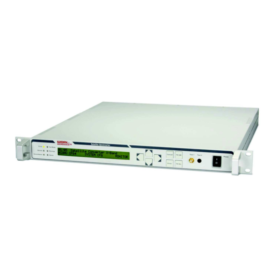
2.5 Front Panel Figure 5: Front panel 1 – Status LED’s for TX On, Test Mode, Remote Status/Activity, Warnings, Stored Alarms, Alarms 2 – LCD Display in VSCU units, VFD Display in VHCU units 3 – Cursor keys 4 – Function keys 5 –... - Page 14 Satellite Upconverter Manual WORK Microwave Figure 7: Rear panel of a dual channel device 1 – Power Supply AC Input 100 … 240 V including mains fuses 2 – Alarm/mute interface 3 – USB 2.0 interface 4 – M&C remote control serial interface RS485/RS232 5 –...
-
Page 15: Connectors On The Rear Panel
Satellite Upconverter Manual WORK Microwave 2.7 Connectors on the Rear Panel 2.7.1 Mains AC Input Connector Block The mains AC input connector block includes a male power input connector according to IEC/EN 60320. It also includes two mains fuse (type 5 x 20 mm). The allowed ranges for the AC input voltage, the input fre- quency are printed on the label near the connector block. -
Page 16: Serial Interface For Rs232 Or Rs485
Satellite Upconverter Manual WORK Microwave USB Interface VBUS The USB interface can supply at maximum 100 mA / 5 V. 2.7.4 Serial Interface for RS232 or RS485 The serial interface connector for RS232 or RS485 is located on the rear panel and can be configured via the front panel to RS485 or RS232. -
Page 17: Rf Output Connector
Satellite Upconverter Manual WORK Microwave The configuration of the IP Address, Subnet Mask, the IP Gateway and the Port for TCP/IP and UDP connec- tions can be configured using the front panel menu or remote access. Within the TCP/IP packets commands according to the multipoint syntax and command structure can be used for remote monitoring and control. -
Page 18: Reference Signal Input
Satellite Upconverter Manual WORK Microwave 2.7.11 Reference Signal Input At the “Ref. In” connector (BNC, 50 W, female) an external reference signal can be connected. The frequency can be either 10 MHz or 5 MHz. See chapter 3.5.2.7 for configuration options and details about this input. -
Page 19: Front Panel Operation
Satellite Upconverter Manual WORK Microwave 3 Front Panel Operation 3.1 Power Switch With the power switch on the front panel the mains supply for the Upconverter can be switched on or off. The switch is recessed to achieve protection against unintentional operation. -
Page 20: Display And Keypad
Satellite Upconverter Manual WORK Microwave 3.4 Display and Keypad All converter functions can be accessed via the front panel display and keypad or via the M&C remote control interfaces. Figure 12: User Interface with display and keypad The display has 40 columns, 2 rows. Within standard type units a LCD-Display with illumination, within high performance type units a VFD display is used. -
Page 21: Conv Cfg
Satellite Upconverter Manual WORK Microwave 3.5.2 CONV CFG The item “CONV CFG” in the main menu allows access to the configuration of the main operational parame- ters of the converter. This menu point is not shown if the REMOTE/LOCAL feature is enabled and if the unit is in REMOTE mode. -
Page 22: If Frequency (Option)
Satellite Upconverter Manual WORK Microwave 3.5.2.5 IF FREQUENCY (Option) The item “IF FREQUENCY” in the “CONV CFG” submenu allows the configuration of the IF output center frequency of the Upconverter. The parameter values which can be selected are: “70 MHz” or “140 MHz”. -
Page 23: M&C Interface Settings
Satellite Upconverter Manual WORK Microwave If Auto Save mode is set to ON, the current parameters are stored in instrument state 00. If Auto Save mode is set to OFF, parameters are not automatically stored in instrument state 00. 3.5.3.4 M&C INTERFACE SETTINGS The item “M&C INTERFACE SETTINGS”... -
Page 24: External Mute Input
Satellite Upconverter Manual WORK Microwave 3.5.3.4.10 M&C SUBNET MASK The item “M&C SUBNET MASK” in the “M&C INTERFACE SETTINGS” submenu allows to configure the IP Subnet Mask of the Ethernet M&C-Interface. 3.5.3.4.11 M&C GATEWAY ADDR The item “M&C GATEWAY ADDR” in the “M&C INTERFACE SETTINGS” submenu allows to configure the IP Gateway Address for the Ethernet M&C-Interface. -
Page 25: Alarm Relay Test
Satellite Upconverter Manual WORK Microwave 3.5.3.7 ALARM RELAY TEST The item “ALARM RELAY TEST” in the “SYSTEM CFG” submenu allows to test the build in alarm relay. After confirming this function by pressing the “Enter” key twice the alarm relay contactors will toggle for approx. 3 seconds. -
Page 26: On/Off Keys
Satellite Upconverter Manual WORK Microwave 3.5.3.13 ON/OFF KEYS The item “ON/OFF KEYS” in the “SYSTEM CFG” submenu allows to enable or disable the function of the "TX On" and "TX Off" keys. If the on/off keys are disabled (keys are not operational) by this menu item, the signal output is only changeable through the menu point “SIGNAL OUTPUT”... -
Page 27: Load Factory Default
Satellite Upconverter Manual WORK Microwave 3.5.3.17 LOAD FACTORY DEFAULT The item “LOAD FACTORY DEFAULT” in the “SYSTEM CFG” submenu allows to activate a factory default for all operational parameters of the unit. The factory default values are as follows: Converter... -
Page 28: Converter Monitor
Satellite Upconverter Manual WORK Microwave 3.5.4.1 CONVERTER MONITOR The currently configured RF frequency, attenuation, reference clock source configuration and equalization are displayed within this menu item. The meaning of the reference source indication (Ref) is as follows: · INT Reference is configured to INTERNAL mode ·... -
Page 29: Status
Satellite Upconverter Manual WORK Microwave 3.5.5 STATUS 3.5.5.1 CONVERTER STATUS The item “STATUS” in the main menu allows access to display the current alarm status of the Converter. After pressing “ENTER” the bit map for the alarm status is displayed on the top display line with an 8 charac- ters (32 Bit) long hex number. -
Page 30: Stored Evt
Satellite Upconverter Manual WORK Microwave 3.5.6 STORED EVT The item “STORED EVT” in the main menu allows access to display the stored events of the Converter. After this menu item was selected with the left or right arrow keys the items of the submenu belonging to this main menu item can be activated by pressing the “Enter”... -
Page 31: Remote Control Description
Satellite Upconverter Manual WORK Microwave 4 Remote Control Description 4.1 Overview The converter unit can be remotely controlled through the serial interface or the Ethernet/IP-interface. The serial interface can be configured by commands or by the front panel menu to RS232 or to RS422/RS485. -
Page 32: Response And Error Codes
Satellite Upconverter Manual WORK Microwave · The single characters are converted to their decimal value c , , each c , is subtracted by decimal 32 · All decimal value are added (incl. header and trailer) · calculate the result modulus decimal 95 ·... -
Page 33: List Of 'Multipoint' Commands
Satellite Upconverter Manual WORK Microwave 4.2.5 List of ‘MULTIPOINT’ Commands OPCO Function Allowed Parameters Examples (device address ‘A’) {AF14500000}- 14500.000 MHz RF frequency Frequency (kHz), ? {AF?}! Note: The reply is without leading zeros. Frequency (10 Hz), ? {AFE1375000000}x 13750.00000 MHz... - Page 34 Satellite Upconverter Manual WORK Microwave {AID}) Front panel device ID Firmware Identification ID-No, None {AID0}9 Front panel device ID Strings {AID1}: Base system ID (The opcode ‘VW’ is due {AID2}; Interface module ID to compatibility reasons) {AID3}< OCXO reference module ID...
- Page 35 Satellite Upconverter Manual WORK Microwave {AEA?}A read number of history entries Alarm History Query Number, ? {AEA1}3 read first history entry {AEA2}4 read second history entry … Response: {AEAnnSssssDyyyymmddThhmmss} max. history entries ssss: Status (Bit16 – Bit 31 see 3.5.4.2)
-
Page 36: Command Parameter Tables
Satellite Upconverter Manual WORK Microwave Actual reference source: 0=int.,1=ext. ddd: reserved, currently 000 Alarm relay: 0=disabled, 1=enabled Warning and Alarm Bits: OCXO oven cold: 0=Ok, 1=cold Reference Alarm: 0=OK / 1=Alarm reserved, always 0 reserved, always 0 reserved, always 0... - Page 37 Satellite Upconverter Manual WORK Microwave Event Event Power Up ext. muting off Oven warm Output off set to internal reference Output on set to external reference ext. muting on Figure 15: Events for Command EE Bit 7 Bit 6 Bit 5...
-
Page 38: Web Browser Interface
Satellite Upconverter Manual WORK Microwave 4.4 Web Browser Interface A web server is included within the firmware of the unit. It can be accessed with any web browser, preferable with Mozilla Firefox. A SSL based secure connection is also supported. -
Page 39: Status Indicators
Satellite Upconverter Manual WORK Microwave Figure 18: Page sections 1. Status indicators 2. Navigation bar 3. Main area The three areas are described in the following chapters. 4.4.1 Status Indicators The two most important status indicators of the device are always displayed on the upper left. The different status types are illustrated in the table below. -
Page 40: Navigation Bar
Satellite Upconverter Manual WORK Microwave Field Symbol Status explanation Status There is no status warning or alarm. Device status warning active. An alarm condition is pending. Signal The output signal is switched on. The output signal is switched off. The output signal is muted temporarily due to a warning or an alarm (e.g. -
Page 41: Local Backup And Restore
Satellite Upconverter Manual WORK Microwave Figure 20: Configuration backup and restore page 4.5.1 Local Backup and Restore For this option a flash disk has to be attached to the USB interface of the device. The initialization of the backup- or restore process is done with the web interface (System Configuration – Upload/Download). To save the current configuration to a flash disk, the “Backup Configuration”... -
Page 42: Saved Configurations
Satellite Upconverter Manual WORK Microwave To download the currently working configuration the “Download Configuration” button has to be pressed. The file “config.xml” is downloaded to the computer. It contains the device configuration in a XML format. For uploading the configuration the path to the file has to be entered in the line above the “Upload Configura- tion”... -
Page 43: Firmware Updates
Satellite Upconverter Manual WORK Microwave 4.6 Firmware Updates Within the device there are various modules with firmware. Every firmware version can easily be upgraded with the communication module. The device needs to be rebooted after every firmware update. 4.6.1 Local Firmware Update The firmware of the all modules including the communication controller can be updated locally with the USB interface of the device. -
Page 44: Snmp Interface
NsaSoft FreeSNMP. Not all of these tools (especially KS-Soft MIB Browser) do understand SMIv2 correctly, in which all MIBs of WORK Microwave are written. Further the included MIB compilers differ in how strict they interpret the macro language (i.e. AdRem SNMP Manager is way more strict than the iReasoning browser). -
Page 45: Snmp Oid Table
WORK Microwave 4.7.1 SNMP OID Table The base OID is 1.3.6.1.4.1.29890.1. This Base ID is identical for all WORK Microwave devices and has to be combined with the OID in the table below. For example, to set the attenuation the entire OID is: 1.3.6.1.4.1.29890.1.5.3.1.1.3. - Page 46 Satellite Upconverter Manual WORK Microwave conv2InterfaceID .5.3.2.50.3 Reads the interface module firmware ID conv2ReferenceID .5.3.2.50.4 Reads the reference module firmware ID conv2SynthesizerID .5.3.2.50.5 Reads the synthesizer module firmware ID conv2AmplifierID .5.3.2.50.6 Reads the amplifier module firmware ID conv2ReadOnlyCommunityName .5.3.2.99.1 Sets and reads the SNMP read-only community name conv2ReadWriteCommunityName .5.3.2.99.2...
-
Page 47: Maintenance And Service
5.4. Please fax or send this form to the address which you find on the form. You will then receive an RMA number which allows easier equipment tracking. 5.3 Company Address WORK Microwave GmbH Raiffeisenstrasse 12 83607 Holzkirchen Germany Tel. -
Page 48: Rma Request Form
Date/Signature of WORK Microwave employee: Please send the device to the following address and state the RMA number: WORK Microwave GmbH, Raiffeisenstrasse 12, 83607 Holzkirchen, Germany Device to be returned to WORK Microwave DDP, Delivered Duty Paid (Incoterms). 48 / 49 V151207... -
Page 49: Appendix
Satellite Upconverter Manual WORK Microwave 6 Appendix 6.1 Technical Data A separate data sheet is attached at the end of this manual. 6.2 Notes Place for own notes: 49 / 49 V151207...
Need help?
Do you have a question about the VSCU and is the answer not in the manual?
Questions and answers